Table of Contents
Advertisement
Quick Links
Instructions - Parts List
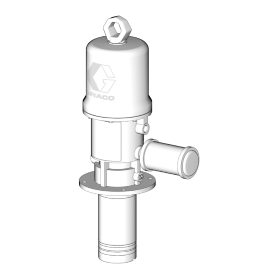
3:1 Fire-Ball
For pumping non-corrosive and non-abrasive oils and lubricants. For professional use
only.
Not approved for use in European explosive atmosphere locations.
Model 237526, Series B
540 psi (3.7 MPa, 37 bar) Maximum Working Pressure
180 psi (1.2 MPA, 12 bar) Maximum Air Input Pressure
Important Safety Instructions
Read all warnings and instructions in this
manual before using the equipment.
Save these instructions.
Related Manuals
Manual in
Description
English
308201
Pump Runaway Valve
®
425 Pump
308485R
EN
Advertisement
Table of Contents

Related Manuals for Graco 237526


Summary of Contents for Graco 237526
-
Page 1: Related Manuals
For pumping non-corrosive and non-abrasive oils and lubricants. For professional use only. Not approved for use in European explosive atmosphere locations. Model 237526, Series B 540 psi (3.7 MPa, 37 bar) Maximum Working Pressure 180 psi (1.2 MPA, 12 bar) Maximum Air Input Pressure... -
Page 2: Table Of Contents
Dimensions ....... 21 Model 237526 Pump, Series B ... . . 21 Mounting Hole Layout . -
Page 3: Warnings
Warnings Warnings The following warnings are for the setup, use, grounding, maintenance, and repair of this equipment. The exclamation point symbol alerts you to a general warning and the hazard symbols refer to procedure-specific risks. When these symbols appear in the body of this manual or on warning labels, refer back to these Warnings. Product-specific hazard symbols and warnings not covered in this section may appear throughout the body of this manual where applicable. - Page 4 Warnings WARNING TOXIC FLUID OR FUMES HAZARD Toxic fluids or fumes can cause serious injury or death if splashed in the eyes or on skin, inhaled, or swallowed. • Read Safety Data Sheets (SDSs) to know the specific hazards of the fluids you are using. •...
-
Page 5: Typical Installation
The typical installation shown in F . 1 is only a guide for selection and installation of a pump. It is not an actual system design. Contact your Graco representative or Graco distributor for assistance in the design of a suitable system. -
Page 6: Installation
Installation Installation System Accessories • Install an air line lubricator (N) for automatic air motor lubrication. NOTICE • Install a bleed-type master air valve (A) to relieve air trapped between it and the motor when the valve is Do not hang the air accessories directly on the air inlet closed. -
Page 7: Grounding
Installation Grounding Air and fluid hoses: use only electrically conductive hoses. Air compressor: follow manufacturer’s The equipment must be grounded to reduce the risk recommendations. of static sparking. Static sparking can cause fumes to ignite or explode. Grounding provides an escape Fluid supply container: follow local code. -
Page 8: Operation
Operation Operation Pressure Relief Procedure To determine the fluid output pressure using the air regulator reading, multiply the ratio of the pump by the air pressure shown on the regulator gauge. For Follow the Pressure Relief Procedure whenever example: you see this symbol. 3 (:1) ratio x 180 psi air = 540 psi fluid output 3 (:1) ratio x 12 bar air = 36 bar fluid output 3 (:1) ratio x 1.2 MPa air = 3.6 MPa fluid output... - Page 9 Operation NOTE: Stop the pump if it is accelerating too quickly or is running too fast, and check the fluid supply. If the supply container is empty and air has been pumped into the lines, prime the pump and lines with fluid, or flush it and leave filled with a compatible solvent.
-
Page 10: Recycling And Disposal
Recycling and Disposal Recycling and Disposal End of Product Life At the end of the product’s useful life, dismantle and recycle it in a responsible manner. • Perform the Pressure Relief Procedure in your pump manual. • Drain and dispose of fluids according to applicable regulations. -
Page 11: Troubleshooting
Troubleshooting Troubleshooting 1. Follow Pressure Relief Procedure, page 8, before checking or repairing the pump. 2. Check all possible problems and causes before disassembling pump. Problem Cause Solution Pump fails to operate. Inadequate air supply pressure or Increase air supply; clear restricted air lines Closed or clogged dispensing valve Open;... -
Page 12: Repair
Repair Repair NOTICE Do not damage the plated surface of the trip rod (31). Damaging the surface of the trip rod can result in erratic air motor operation. Use the padded pliers (207579) to grasp the rod. This equipment stays pressurized until pressure is 7. - Page 13 Repair 9. Pull the piston assembly from the air motor base 16. Clean all of the parts carefully in a compatible (28) and set it aside. solvent and inspect them for wear or damage. Use all of the repair kit parts during reassembly, and 10.
- Page 14 Repair Cutaway View . 4 Air Motor and Throat Reassembly 4. Grease heavily and place the trip rod (31) in the piston, place the actuator (12) in the yoke (13), and Ensure that all necessary parts are on hand. Air Motor place the well-greased actuator/yoke assembly in Repair Kit 207385 includes repair parts for the motor.
-
Page 15: Displacement Pump
Repair 21. Reconnect the ground wire before regular NOTICE operation of the pump. Do not reuse the old lock wires. They become brittle and break from too much bending. Displacement Pump 9. Align the holes in the valve nuts (21*) and the slots Disassembly on the top of the inlet valve poppets (32*), and drop the lock wires (22*) through the holes in the valve... - Page 16 Repair Reassembly Follow steps 15 through 15 of Air Motor and Throat Reassembly, page 14. †Included in Pump Repair Kit 237602, which may be purchased separately. 308485R...
-
Page 17: Parts
Parts Parts Pump Model 237526, Series B Air motor not listed or shown here. See pages 18 and 19. Parts List Ref. Part Description Qty. 194016 PISTON Ref. Part Description Qty. 190922 CYLINDER, pump 10† 112130 SEAL, u-cup (shown on page 18) -
Page 18: Air Motor
Parts Air Motor See Pump Parts Drawing and List, page 15. 308485R... - Page 19 Parts Air Motor Parts List Ref. Part Description Qty. 101578 SCREW, cap, hex hd 102656 MUFFLER, air exhaust 116343 SCREW, ground 10† 112130 SEAL, u-cup 156698 PACKING, o-ring 158359 ACTUATOR, air valve 158360 YOKE, trip rod 158362 PIN, toggle 158364 PIN, pivot 158367 GROMMET, inlet valve 158377 PACKING, ring seal 158378 PACKING, o-ring...
-
Page 20: Performance Charts
Performance Charts Performance Charts 308485R... -
Page 21: Dimensions
Dimensions Dimensions Model 237526 Pump, Series B Mounting Hole Layout 308485R... -
Page 22: Technical Specifications
Technical Specifications Technical Specifications 3:1 Fire-Ball 425 Pump Metric Maximum working pressure 540 psi 3.7 MPa, 37bar Fluid pressure ratio 40 to 180 psi 0.28 MPa to 1.24 MPa, Air operating range 2.76 bar to 12.4 bar Air consumption at 100 psi (0.7 MPa, 7 bar) 3 ft /min per gallon pumped 0.022 m... -
Page 23: California Proposition 65
California Proposition 65 California Proposition 65 CALIFORNIA RESIDENTS WARNING: Cancer and reproductive harm – www.P65warnings.ca.gov. 308485R... -
Page 24: Graco 10-Year Pump Warranty
With the exception of any special, extended, or limited warranty published by Graco, Graco will, for a period from the date of sale as defined in the table below, repair or replace equipment covered by this warranty and determined by Graco to be defective.
Need help?
Do you have a question about the 237526 and is the answer not in the manual?
Questions and answers