Table of Contents
Advertisement
Instructions - Parts List
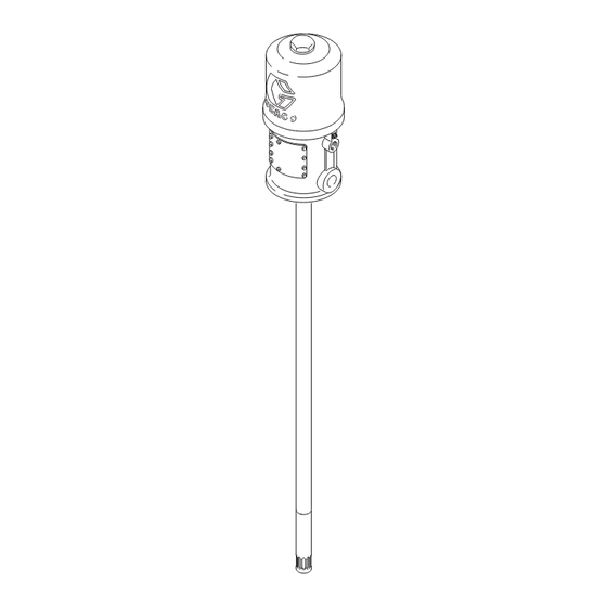
50:1 Fire-Ball
425 Pumps
For pumping non-corrosive and non-abrasive greases and lubricants only. For
professional use only.
Model 205394, Series E
Model 205395, Series N
7500 psi (51.7 MPa, 517 bar) Maximum Working
Pressure
150 psi (1.0 MPa, 10 bar) Maximum Air Input Pressure
Important Safety Instructions
Read all warnings and instructions in this
manual. Save these instructions.
This pump is designed to be used only in pumping
non-corrosive and non-abrasive oils and lubricants.
Any other use of the pump can cause unsafe
operating conditions and component rupture, which
can result in fluid injection or other serious injury or
fire or explosion.
®
306674W
EN
Advertisement
Table of Contents

Subscribe to Our Youtube Channel
Related Manuals for Graco 205394


Summary of Contents for Graco 205394
- Page 1 425 Pumps 306674W For pumping non-corrosive and non-abrasive greases and lubricants only. For professional use only. Model 205394, Series E Model 205395, Series N 7500 psi (51.7 MPa, 517 bar) Maximum Working Pressure 150 psi (1.0 MPa, 10 bar) Maximum Air Input Pressure...
- Page 2 Warnings Warnings The following warnings are for the setup, use, grounding, maintenance, and repair of this equipment. The exclama- tion point symbol alerts you to a general warning and the hazard symbols refer to procedure-specific risks. When these symbols appear in the body of this manual or on warning labels, refer back to these Warnings. Product-specific hazard symbols and warnings not covered in this section may appear throughout the body of this manual where applicable.
- Page 3 Warnings WARNING EQUIPMENT MISUSE HAZARD Misuse can cause death or serious injury. • Do not operate the unit when fatigued or under the influence of drugs or alcohol. • Do not exceed the maximum working pressure or temperature rating of the lowest rated system com- ponent.
-
Page 4: Mounting The Pump
Installation Installation Grounding To ground the pump: Remove the ground screw (Z) and insert through the eye of the ring terminal at end of ground wire (Y). Fasten the ground screw back onto the pump and tighten securely. Connect the other end of the ground wire to a true earth ground. - Page 5 Installation Be sure the air hose is properly sized to deliver an ade- quate supply of air to the motor. Refer to the Technical Data on page 16. A bleed-type master air valve (B) is required to shut Connect a dispensing hose to the 3/8 npt(f) pump outlet. off an relieve air pressure that may be trapped in the Install an appropriate gun or dispense valve to the hose.
-
Page 6: Operation
Operation Operation Pressure Relief Procedure Startup and Adjustment Follow the Pressure Relief Procedure whenever you see this symbol. Open the bleed-type air master valve (B). Open the dis- pensing valve (G), and slowly open the air regulator (E) until the pump is running smoothly. After all the air is This equipment stays pressurized until pressure is purged, close the dispensing valve. -
Page 7: Troubleshooting
Troubleshooting Troubleshooting 1. Follow Pressure Relief Procedure, page 6, before checking or repairing gun. 2. Check all possible problems and causes before dis- assembling gun. Problem Cause Solution Inadequate air supply pressure or Increase air supply; clear restricted air lines. Closed or clogged valves Open;... - Page 8 Service Service Ref. 63 (copper gasket) and Ref. 60 (cotter pin), see Parts Drawing on page 16. 1/4” ROD 306674W...
-
Page 9: Displacement Pump
Service Displacement Pump in (6 mm) diameter rod through the holes in the tube. Handle the tube carefully to avoid marring the surface. Remove the ball, seat, and gasket. 7. Unscrew the intake valve housing (67) from the pis- ton valve housing (64). Remove the ball and pack- Before starting: ings. -
Page 10: Air Motor And Throat Service
Service Air Motor and Throat Service NOTICE Do not damage the plated surface of the trip rod. Before starting: Damaging the surface of the trip rod can result in erratic air motor operation. Use the special padded • Be sure to have all necessary parts on hand. Air pliers, 207579, to grasp the rod. -
Page 11: Throat Packing
Service Push toggles (K) in and then up. ut off tops of poppets (x) as Turn wires up. indicated by dotted lines 0.125 in. (3.18 mm) CUTAWAY VIEW Reassembly 7. Before installing the lockwires (28) in the adjusting nuts (27), use the special gauge, 171818, to adjust 1. - Page 12 Service 2. Remove the cotter pin (60) and unscrew the pump NOTE: Make sure the packing (25) lips face down and connecting rod (79) from the air motor piston rod make sure the wiper (22) lips face up. (52). Remove the cylinder (32) from the air motor base (56) as described under Disassembly on page 8.
- Page 13 Notes Notes 306674W...
- Page 14 Parts Parts 306674W...
- Page 15 Parts Model 205394, Series E, 120 lb. (55 kg) drum length Model 205395, Series N, 400 lb. (180 kg) drum length Ref. Part Description Qty. Ref. Part Description Qty. 116343 SCREW, grounding 207150 TRIP ROD 165362 BASE, motor, air 207391 PISTON, includes items 3 to 5 (also 58...
-
Page 16: Technical Data
19 cfm at 1 approximately 0.53 m /min at gpm at 70 psi 3.8 lpm at 0.48 MPa, 4.8 bar Wetted parts Steel, brass, aluminum, leather Weight Model 205394 34 lb 15 kg Model 205395 37 lb 17 kg 306674W... -
Page 17: Mounting Holes
1/2 npt(f) 48–3/16” Air Inlet Air Inlet (1224 mm) 26–11/16” 33–5/8” (678 mm) (854.1 mm) Priming Piston Priming Piston Model 205394, Series E Model 205395, Series N Weight 36 lb (16 kg) Weight 36 lb (16 kg) Mounting Holes 306674W... -
Page 18: Graco Standard Warranty
With the exception of any special, extended, or limited warranty published by Graco, Graco will, for a period of twelve months from the date of sale, repair or replace any part of the equipment determined by Graco to be defective.
Need help?
Do you have a question about the 205394 and is the answer not in the manual?
Questions and answers