Dynon EFIS-D10A Installation & Maintenance Manual
Standby display
Hide thumbs
Also See for EFIS-D10A:
- Installation and maintenance manual (34 pages) ,
- Installation manual (105 pages)
Table of Contents
Advertisement
Quick Links
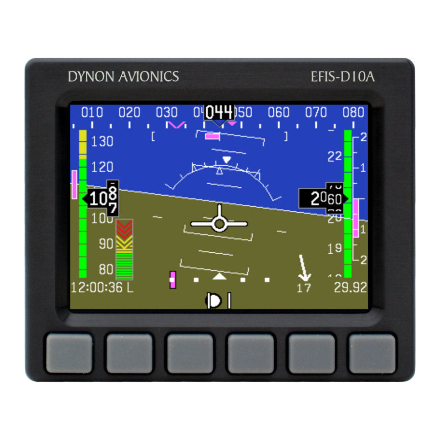
EFIS-D10A Standby Display
Installation & Maintenance Manual
Includes Instructions for Continued Airworthiness
The EFIS-D10A Standby Display must be used in conjunction with SkyView HDX.
103914-000
Revision A
2/4/2020
Copyright © 2020 by Dynon Avionics, Inc.
Dynon Avionics grants third parties' permission to print this document
Advertisement
Table of Contents

Related Manuals for Dynon EFIS-D10A


Summary of Contents for Dynon EFIS-D10A
- Page 1 EFIS-D10A Standby Display Installation & Maintenance Manual Includes Instructions for Continued Airworthiness The EFIS-D10A Standby Display must be used in conjunction with SkyView HDX. 103914-000 Revision A 2/4/2020 Copyright © 2020 by Dynon Avionics, Inc. Dynon Avionics grants third parties' permission to print this document...
- Page 2 Information in this document is subject to change without notice. Dynon Avionics reserves the right to change or improve its products and to make changes in the content without obligation to notify any person or organization of such changes.
- Page 3 Revision History DATE APPROVED DESCRIPTION OF CHANGE 2/4/2020 ECO 341990 Initial Release EFIS-D10A Standby Display - Installation & Maintenance Manual, Revision A Page | 3...
-
Page 4: Table Of Contents
Backup Battery Test ....................18 Backup Battery Replacement ..................18 EFIS-D10A Removal and Re-Installation ..............19 IFR Altimeter System Equipment Test (FAR 91.411) ..........21 Firmware Updates ...................... 21 Page | 4 EFIS-D10A Standby Display - Installation & Maintenance Manual, Revision A... -
Page 5: Introduction
The information in this manual is general to all airplanes on the Approved Model List (AML) of Supplemental Type Certificate (STC) SA02594SE. In Certified installations, the EFIS-D10A serves as a standby display for the Primary Flight Display (PFD). The EFIS-D10A uses internal calibrated sensors to present Airspeed, Altitude, and Attitude data. -
Page 6: Product Registration
Using this Manual To reduce paper usage, Dynon Avionics does not provide a printed version of this manual. However, Dynon Avionics grants permission to third parties to print this manual as necessary. -
Page 7: Reference Documents
It is the responsibility of the mechanic or facility performing the installation to record where equipment is installed in the airplane. Dynon Avionics provides a form (SkyView HDX Certified Equipment Installation Record) to record this information. Authorized installers can download the document at www.dynon.aero/stcdocs. -
Page 8: Pre-Installation Information
Installers should review and become familiar with the information and procedures in this document before beginning an installation. Page | 8 EFIS-D10A Standby Display - Installation & Maintenance Manual, Revision A... -
Page 9: Instrument Panel Design
Instrument Panel Design Installing an EFIS-D10A often necessitates the design and fabrication of new instrument panel. When designing new instrument panels, installers must adhere to Part 23 of the Code of Federal Regulations guidance and methods for locating equipment that displays flight information. Dynon Avionics provides helpful instrument panel design information for Certified installations in the SkyView HDX Certified Installation Manual document. -
Page 10: Mechanical Installation
Static lines. Use T-connectors to splice into existing Pitot and Static lines. Remove male plugs from Pitot and Static female pipe fittings on EFIS-D10A. Plug in AoA pipe fitting remains in place. Apply Teflon tape and thread 1/8" NPT adapters into Pitot and Static female fittings on EFIS-D10A. - Page 11 Connect existing Pitot and Static lines to corresponding 1/8" NPT adapters on EFIS-D10A. Figure 3: EFIS-D10A, Panel Cutout & Mounting Dimensions EFIS-D10A Standby Display - Installation & Maintenance Manual, Revision A Page | 11...
-
Page 12: Electrical Installation
Electrical Installation The EFIS-D10A is shipped with D25F wire harness that plugs into the D25M connector on the rear of the unit. The wire harness has designated wires for connection to airplane power (see Table 1 for pin/wire connections). Table 1: EFIS D10A, Pin/Wire Connection... -
Page 13: Configuration
Configuration There are a few simple configuration tasks that must be completed before using the EFIS-D10A. This section guides you through those tasks. Prior to shipping, the EFIS-D10A undergoes a comprehensive calibration, verification, and burn-in routine to minimize setup time and to ensure every unit meets Dynon Avionics' stringent performance specifications. - Page 14 Find a Menu Item associate with a function. Press MORE to scroll through Menu Items. Toggle function on/off or configure function as needed (see Table 2 for details). When finished, press BACK to return to previous menu. Page | 14 EFIS-D10A Standby Display - Installation & Maintenance Manual, Revision A...
-
Page 15: Airspeed Color Bar Thresholds
(except left and right hotkeys) on EFIS page, and then pressing MORE > SETUP > UNITS > IAS. Always make sure the EFIS-D10A airspeed unit is the same as the SkyView HDX display airspeed unit. -
Page 16: Zero Pitch Calibration
Press INC - or DEC + until the horizon line intersects the center of the crosshairs. When finished, press BACK > EXIT. This calibration must be performed while the airplane is level to ensure proper pitch and roll display throughout all maneuvers. Page | 16 EFIS-D10A Standby Display - Installation & Maintenance Manual, Revision A... -
Page 17: Troubleshooting
Troubleshooting The EFIS-D10A includes limited self-diagnostic capability. If a fault with the EFIS-D10A is detected, a message will be displayed on the screen. The following table provides a recommendation for each specific warning. Table 3: EFIS-D10A Self-Diagnostic Messages MESSAGE POSSIBLE CAUSES... -
Page 18: Maintenance
Maintenance Backup Battery Test The EFIS-D10A backup battery must be tested once every 12 months to ensure it is operational and meets the nominal 45-minute expected backup operation period. The backup battery must be fully charged prior to beginning the test. -
Page 19: Efis-D10A Removal And Re-Installation
This section provides removal and re-installation procedures for the EFIS-D10A. Location: The EFIS-D10A is typically located on the left side of the instrument panel. For specific location, see the Equipment Installation Record document associated with the airplane. To remove the EFIS-D10A: Shut down main power bus. - Page 20 If original mounting hardware is lost, use AN365-832 (lock nut) and AN960-8 (washer) or comparable for replacement. Restore power to main bus. Check system for leaks (see airplane manufacturer's maintenance manual for instructions). Figure 4: EFIS-D10A, Rear View Page | 20 EFIS-D10A Standby Display - Installation & Maintenance Manual, Revision A...
-
Page 21: Ifr Altimeter System Equipment Test (Far 91.411)
When finished, press BACK > EXIT. Firmware Updates Version 5.4.1 is the latest and final firmware version for the EFIS-D10A. If the unit is running an older version, contact Dynon Avionics Technical Support for help upgrading. To check EFIS-D10A firmware version: •...
Need help?
Do you have a question about the EFIS-D10A and is the answer not in the manual?
Questions and answers