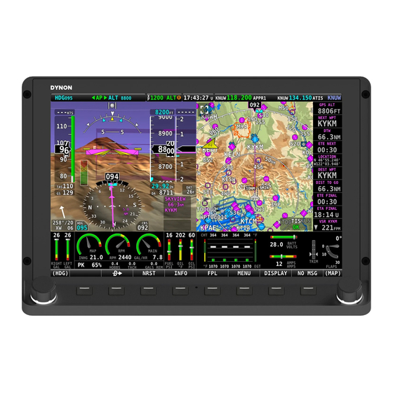
Dynon SkyView HDX Equipment Installation Record
Hide thumbs
Also See for SkyView HDX:
- System installation manual (374 pages) ,
- Airplane flight manual supplement (98 pages) ,
- Configuration manual (27 pages)
Advertisement
Advertisement
Table of Contents

Summary of Contents for Dynon SkyView HDX
- Page 1 SkyView HDX System Equipment Installation Record Airplane Make/Mode/Year: Serial Number: Registration Number: Installer Name / Installation Date: 103777-000 Revision A 7/16/2019 Copyright © 2019 by Dynon Avionics, Inc. Dynon Avionics grants third parties' permission to print this document...
-
Page 2: Contact Information
Information in this document is subject to change without notice. Dynon Avionics reserves the right to change or improve its products and to make changes in the content without obligation to notify any person or organization of such changes. -
Page 3: Revision History
Revision History DATE APPROVED DESCRIPTION OF CHANGE 7/16/2019 ECO 330218 Initial Release SkyView HDX System Equipment Installation Record, Revision A Page | 1... -
Page 4: How To Use This Document
Station, Water, and Buttock Line location as measured from the appropriate datums. Refer to the airplane's maintenance manual to determine an airplane's datum locations. The installer of the SkyView HDX System equipment should use the Three-... - Page 5 SkyView HDX System Equipment Identification and Location Table 1 to list and locate each SkyView HDX system component installed in this airplane. If the component is installed on an avionics tray, simply enter "avionics tray" under Station Location. Table 1: SkyView HDX System Equipment List...
- Page 6 BUTTOCK PART SERIAL STATION WATERLINE COMPONENT LINE NUMBER NUMBER LOCATION LOCATION LOCATION SV-GPS-2020 GPS 503286-000 RECEIVER / ANTENNA USB PORT, PANEL MOUNT, PRIMARY 503418-000 DISPLAY (LEFT) USB PORT, PANEL MOUNT, SECONDARY 503418-000 DISPLAY (CENTER) USB PORT, PANEL MOUNT, SECONDARY 503418-000 DISPLAY (RIGHT) SV-ADAHRS-200 503282-000...
- Page 7 BUTTOCK PART SERIAL STATION WATERLINE COMPONENT LINE NUMBER NUMBER LOCATION LOCATION LOCATION SV-KNOB-PANEL/V KNOB CONTROL PANEL #1 503468-000 (VERTICAL) SV-KNOB-PANEL/H KNOB CONTROL PANEL #2 503471-000 (HORIZONTAL) SV-KNOB-PANEL/V KNOB CONTROL PANEL #2 503468-000 (VERTICAL) SV-AP-PANEL/H AUTOPILOT CONTROL 503465-000 PANEL (HORIZONTAL) SV-AP-PANEL/V AUTOPILOT CONTROL 503463-000 PANEL (VERTICAL)
- Page 8 Three-Point Reference System The SkyView HDX system equipment installed in this airplane can be located using the Three- Point Reference System adopted by the manufacturer of the airplane. Figure 1 is an example of the Three-Point Reference System as applied to a common general aviation airplane.
- Page 9 Fuselage Stations When referring to stations, many airplane manufacturers will use the term Fuselage Stations (FS). Figure 3 is an example of using Fuselage Stations. Figure 3: Example of Fuselage Stations Wing Stations Another form of station is the Wing Station (WS). Wing stations typically reference the vertical centerline of the airplane as the datum and extend along the span of the wings.
- Page 10 Waterline Locations Waterlines (WL) designate the vertical location in inches from a reference point (WL0) typically located below the airplane. Airplane manufacturers will assign a prominent and level feature like the floor and assign it value such as WL75, which is 75 inches above WL0. Figure 5 is an example of waterline references.


Need help?
Do you have a question about the SkyView HDX and is the answer not in the manual?
Questions and answers