Dynon SkyView HDX System Installation Manual
Hide thumbs
Also See for SkyView HDX:
- Airplane flight manual supplement (98 pages) ,
- Configuration manual (27 pages) ,
- Equipment installation record (10 pages)

Related Manuals for Dynon SkyView HDX


Summary of Contents for Dynon SkyView HDX
- Page 1 SkyView HDX System Installation Manual AML STC SA02594SE Document 103261-000, Revision E April 28, 2020 Copyright © 2020 by Dynon Avionics, Inc. Permission to print this manual is granted to third parties.
- Page 3 Information in this document is subject to change without notice. Dynon Avionics reserves the right to change or improve its products and to make changes in the content without obligation to notify any person or organization of such changes. Visit the Dynon Avionics website (www.dynonavionics.com) for current updates and supplemental information concerning the use and operation of this and...
- Page 5 • Added Section 3.1 (new): Avionics Tray Installation • Sections 3, 6, 8-19 re-organized to better match typical order of assembly • Sections 4.10-13 (old) removed because content outdated • Section 5 (old) moved to Section 21 (new) SkyView HDX System Installation Manual - Revision E...
- Page 6 Subsequent Section 10 headings renumbered. • Updated 10.2.11, and 10.2.12 with new fluid sensors sold by Dynon. • Added new Section 3.2: Instrument Panel Material Requirements. Subsequent Section 3 headings renumbered. SkyView HDX System Installation Manual - Revision E...
- Page 7 103272-000 SkyView HDX Airplane Flight Manual Supplement 102949-003 SkyView HDX Pilot’s User Guide 103488-000 WIRING DIAGRAM TYPICAL HDX DUAL DISPLAY 43.13-1B Acceptable Methods, Techniques and Practices- Aircraft Inspection and Repair 43.13-2B Acceptable Methods, Techniques and Practices- Aircraft Alterations SkyView HDX System Installation Manual - Revision E...
-
Page 8: Table Of Contents
Airplane Master Contactor / Relay Considerations ..............4-9 4.3.4 SV-BAT-320 Connection and Operation Rules ................4-9 4.3.5 SkyView Network Connectors ....................4-10 4.3.6 Network Setup and Status ......................4-10 4.3.7 Ethernet Connection ........................4-13 SkyView HDX System Installation Manual - Revision E... - Page 9 6.6.1 In the Event of Initial SV-BAT-320 Test Failure ................6-8 SV-BAT-320 Specifications ......................6-8 Returning an SV-BAT-320 to Dynon Avionics for Exchange (Warranty Replacement) ...... 6-8 SV-ADAHRS-200 ADAHRS Installation and Configuration Mechanical Installation ....................... 7-1 Electrical Installation ........................7-6 Compass Calibration ........................
- Page 10 Example widget configuration ....................10-36 10.8.2 Specific Widget and Info Item Data Requirements ..............10-37 10.9 EMS Sensor Calibration ......................10-37 10.10 SkyView HDX Engine Bottom Band ..................10-38 11 SV-GPS-2020 GPS Antenna/Receiver Installation 11-1 11.1 WAAS Data Reception ....................... 11-1...
- Page 11 SV-HARNESS-ADSB – Pinout (D9F on module / D9M on harness) ..........14-4 14.2.2 Power/Ground Input ........................14-5 14.2.3 Serial RX/TX ..........................14-5 14.3 Antenna Selection and Installation .................... 14-6 14.3.1 Antenna Ground Plane ....................... 14-8 SkyView HDX System Installation Manual - Revision E...
- Page 12 Mechanical Installation ......................20-3 20.7.1 Attaching to Instrument Panel ....................20-5 20.7.2 Connecting Static and Pitot Lines to EFIS-D10A ................20-5 20.8 Post-Installation Configuration and Checkout Procedure ............20-5 20.8.1 Initial Verification ........................20-5 SkyView HDX System Installation Manual - Revision E viii...
- Page 13 Display Bezel Layout ......................... 21-2 21.3 Joystick and Button Operation ....................21-3 21.3.1 Operation Basics ........................21-3 21.3.2 SkyView HDX Knob and Button Operation Example ..............21-3 21.4 Menu Navigation ........................21-4 21.5 Display Operation Procedures ....................21-5 21.5.1 How to Turn the System On or Off ..................... 21-5 21.5.2...
- Page 14 Engine Sensor Does Not Show Up Onscreen ................23-16 24 Appendix B: Specifications 24-1 24.1 Minor Unit Physical Specifications ..................... 24-1 24.2 SkyView Compatible Engine Sensors (sold by Dynon Avionics) ............ 24-1 24.3 SV-BAT-320 Specifications ......................24-3 24.4 SV-XPNDR-261 Specifications ....................24-4 24.5 SV-XPNDR-261 ADS-B Information .....................
- Page 15 DYNON SYSTEM Serial Data Format ................... 27-3 27.3 DYNON EMS Serial Data Format ....................27-6 27.4 DYNON ADAHRS / SYSTEM / EMS Serial Data Output Combinations .......... 27-10 27.5 NMEA OUT Serial Data Formats ....................27-11 28 Appendix F: User Data Logs 28-1 28.1.1...
-
Page 17: Introduction
When a SkyView system is connected to products not manufactured or provided by Dynon Avionics (such as NAV radios and GPS receivers), it is often necessary to refer to those product’s technical/installation manuals/guides to configure their settings and their wiring to be compatible with your SkyView system. -
Page 18: Printing This Manual
This icon denotes information that merits special attention. This icon denotes a helpful installation tip. If your aircraft was built using components not provided by Dynon Avionics (such as harnesses), some information provided in this manual may not be applicable. For example, some manufacturers prefer to build harnesses that do not adhere to the wire color codes of harnesses manufactured by Dynon Avionics. -
Page 19: Installation Record
It is the responsibility of the mechanic or facility performing the installation to record where each component of the SkyView system has been installed in the airplane. This record should be entered into airplane’s permanent record. Dynon Avionics provides a document template (103777-000 SkyView HDX System Equipment Installation Record) to complete the record. -
Page 21: System Overview
System Overview System Overview 2.1 Required Equipment The SkyView HDX System STC SA02594SE requires that the following equipment be installed: • HDX1100 or HDX800 • EFIS-D10A Standby Display • SV-ADAHRS-200 ADAHRS • SV-OAT-340 Outside Air Temperature sensor • SV-GPS-2020 GPS Antenna/Reciever •... -
Page 22: Instrument Panel Mounted Equipment
System Overview 2.3 Instrument Panel Mounted Equipment Examples of the Dynon-provided equipment (required and optional) typically mounted to the instrument panel appear in the figures and table that follow. This information should only be considered as an example of an installation, your airplane may differ. - Page 23 SV-ARINC-429 ARINC 429 Interface Module SV-ADAHRS-200 ADAHRS SV-EMS-220 Engine Monitoring System SV-ADSB-472 ADS-B Receiver HDX1100 Avionics Tray SV-COM-X83 COM Radio Transceiver SV-XPNDR-261 Transponder Mode-S HDX800 Secondary Display HDX800 Secondary Display Avionics Tray SV-BAT-320 Backup Battery SkyView HDX System Installation Manual - Revision E...
- Page 24 System Overview Figure 1: Typical Instrument Panel Front View SkyView HDX System Installation Manual - Revision E...
- Page 25 System Overview Figure 2: Typical Instrument Panel Rear View SkyView HDX System Installation Manual - Revision E...
- Page 26 System Overview Figure 3: HDX1100 Avionics Tray SkyView HDX System Installation Manual - Revision E...
- Page 27 System Overview Figure 4: HDX800 Avionics Tray SkyView HDX System Installation Manual - Revision E...
-
Page 28: Systems And Sub Systems
This section also explains what a SkyView system is and how to build one. To see a high- level diagram of a typical SkyView system, see Figure 5 and Figure 6. Figure 5: Typical SkyView System Overview SkyView HDX System Installation Manual - Revision E... - Page 29 SkyView systems are easily scalable and can accommodate a wide variety of components ranging from a single display with one module to multiple displays with multiple modules. Figure 7 illustrates how the Skyview modules and equipment relate with each other. SkyView HDX System Installation Manual - Revision E...
- Page 30 System Overview Figure 7: SkyView System Diagram with Required and Optional Equipment SkyView HDX System Installation Manual - Revision E 2-10...
- Page 31 Figure 8 illustrates the EMS system and how the sensors and signal sources relate to the EMS module. Figure 8: Engine Monitoring System Diagram with Optional Sensors SkyView HDX System Installation Manual - Revision E 2-11...
-
Page 32: Skyview Network
SV-ADSB-472 ADS-B IN Receiver Installation for details. for details. Dynon Avionics AP servos (wired with the SV-NET-SERVO kit) use D9F and D9M connectors (at the servo) that are not compatible with the SkyView Network; see the section AP Servo Installation and Configuration for details. -
Page 33: External Switches And Indicators
Resolution SV-HDX800 1280 x 800 pixels SV-HDX1100 2.8 Maximum Number of Displays The SkyView HDX system can include as many as three SkyView displays in any combination of SV-HDX800s and SV-HDX1100s. SkyView HDX System Installation Manual - Revision E 2-13... -
Page 34: Specifications
SV-KNOB-PANEL 0.07A 0.04A SV-MAG-236 0.15A 0.08A `For example, a SV-D1000T @ 12V with: 1 – SV-BAT-320 (1.00A), 1 – SV-GPS-2020 (0.10A), 1 – SV-ADAHRS-200 (0.15A), and 1 – SV-EMS-220 (0.11A), SkyView HDX System Installation Manual - Revision E 2-14... - Page 35 Table 4 contains power specifications for SkyView units that are powered from aircraft power (not powered by the SkyView Network). The circuit protection recommendations are suitable for most installations and assume that you are using Dynon Avionics harnesses and/or are following the wiring advice in this Installation Manual. It may be possible to use different sized circuit protection if the protective device has suitable load overhead for the connected device(s).
- Page 36 (-30° C to 60° C) (-40° C to 70° C) -67° F to 185° F -4° F to 158° F SV-XPNDR-261 (-55° C to 85° C) (-20° C to 70° C) SkyView HDX System Installation Manual - Revision E 2-16...
-
Page 37: Power Protection
The SV-NET-SERVO (one kit per servo) makes it easy to connect the SkyView system to Dynon Avionics servos and includes 20 feet of pre-twisted wire (twisted pair 22 AWG wire for data; 20 AWG wire for power), D9 connectors, connector shells, crimp contacts, an insertion tool, heat shrink, and zip ties. -
Page 38: Net-Hub
SkyView network without relying on a more expensive network of individual splitters. It also allows for fewer overall connections over the splitter- only method. Figure 11: SV-NET-HUB Figure 12: SV-NET-HUB Dimensions SkyView HDX System Installation Manual - Revision E 2-18... -
Page 39: Test Skyview Network Cable
The Ethernet connection between SkyView displays is in addition to the SkyView Network connections, and should be connected on a permanent basis like other SkyView wiring. Dynon Avionics requires “Low Smoke Zero Halogen” Ethernet cables for use in aircraft. Low Smoke Zero Halogen Ethernet cables are available from Dynon Avionics (SV- ETHERNET-3CC). -
Page 40: Quick Start
11 (Orange wire), 12 (Yellow wire), and 30 (Black wire). This connector is used for other Dynon Avionics products, but is not used in SkyView installations. Thus, the 9-pin connector should be removed to use these wires for connecting sensors to the SV-EMS-220. - Page 41 12. Your SkyView System may require various updates, such as system Software, databases, and Sensor Definitions. See http://downloads.dynonavionics.com certified products for more details on the updates available for the SkyView HDX System. 13. Common issues for setting up SkyView engine monitoring: a.
- Page 42 Traffic will not be displayed unless you are in an area covered by an TIS radar site (US only). 15. Common issues for setting up Dynon Avionics Autopilot: a. Servos must be powered ON. b. Servos must be recognized on the SkyView Network (above).
-
Page 43: Instrument Panel Design
Instrument Panel Design Instrument Panel Design Installing SkyView HDX necessitates the design and fabrication of a new instrument panel to mount the SkyView panel-mounted equipment. This section provides quantified and qualified regulatory guidance, as well as volumetric requirements for the SkyView panel- mounted equipment to help you decide where to locate equipment on the instrument panel. -
Page 44: Instrument Panel Material Requirements
To maintain structural integrity of the aluminum instrument panel, make sure the instrument panel design incorporates a minimum 3/4" (0.75") edge margin around the perimeter of all cutouts for SkyView HDX displays. Additionally, design all replacement instrument panels in accordance with the guidance for sheet metal thickness in Table 8. -
Page 45: Primary Flight Information
The FAA defines the Attitude, Altimeter, Airspeed, and the Heading information (shown arranged in the traditional analog T-layout in Figure 13) as the the Primary Flight Information (PFI). In SkyView HDX display, the PFI appears in the area of the display called the Primary Flight Display (PFD). -
Page 46: Primary Field-Of-View
AC 23.1311-1C Section 15.4 Table 3, the resulting horizontal boundary dimension of the primary maximum field-of-view is 8.00 inches on either side of the pilot’s position centerline reference, as shown in Figure 15. SkyView HDX System Installation Manual - Revision E... - Page 47 • Vertically as high in the instrument panel as practical while avoiding any visual occlusion from potential obstructions such as the glareshield. As demonstrated in Figure 15, the SkyView HDX display and the EFIS-D10A display can confortably fit within the calculated boundaries of the Primary Field-of-View as they are defined by AC 23.1311-1C Section 15.4 Table 3.
- Page 48 AC 23.1311-1C Section 15.4 Table 3, the resulting horizontal boundary dimension of the primary maximum field-of-view is 21.0 inches on either side of the pilot’s position centerline reference, as shown in Figure 17. SkyView HDX System Installation Manual - Revision E...
-
Page 49: Primary Maximum Field-Of-View
These factors should include the following: • Readability • Frequency of use and criticality • Clutter • Attention-getting • Pilot scan pattern • Out-the-window correlation • Pilot workload • Pilot disorientation • Parallax • Illumination and glare SkyView HDX System Installation Manual - Revision E... -
Page 50: Qualitative Assesment
COM, Autopilot, and Knob Control Panels. All volumetric space dimensions include additional space for the “worst-case” electrical connectors and harnesses bent 90 degrees at minimum bend radius. Figure 18: EFIS-D10A Standby Display SkyView HDX System Installation Manual - Revision E... - Page 51 Instrument Panel Design Figure 19: SkyView HDX1100 Display, without Avionics Tray Figure 20: SkyView HDX1100 Display, with Avionics Tray SkyView HDX System Installation Manual - Revision E...
- Page 52 Instrument Panel Design Figure 21: SkyView HDX800 Display, without Avionics Tray Figure 22: SkyView HDX800 Display, with Avionics Tray SkyView HDX System Installation Manual - Revision E...
- Page 53 Instrument Panel Design Figure 23 SkyView Control Panel, Typical SkyView HDX System Installation Manual - Revision E...
-
Page 55: Skyview Hdx Display Installation And Configuration
This section contains information and diagrams that specifically apply to the installation of SkyView HDX System per STC SA02594SE. After reading this section, you should be able to determine how to prepare a panel for display installation, how to mount a display, how to make all necessary electrical connections, and how to generally configure the display. - Page 56 (Outside North update Database? America) firmware Download and Download and Download and Install terrain Install aviation Install firmware database database Configure display Settings and Skyview network Figure 24: Suggested SkyView Display Installation Procedure SkyView HDX System Installation Manual - Revision E...
-
Page 57: Avionics Tray Installation
• SV-BAT-320 Backup Battery • SV-COM-T8 Transceiver or SV-XPNDR-261 Transponder Prepare the instrument panel cut out for the SkyView HDX display the same as you would without an avionics tray. The panel cut-out dimensions are provided in both the HDX Display panel drawings as well as the following avionics tray drawings. - Page 58 SkyView HDX Display Installation and Configuration Figure 25: SV-HDX1100 Avionics Tray Mounting Dimensions (Not to Scale) SkyView HDX System Installation Manual - Revision E...
- Page 59 SkyView HDX Display Installation and Configuration Figure 26: SV-HDX800 Secondary Avionics Tray Mounting Dimensions (Not to Scale) SkyView HDX System Installation Manual - Revision E...
-
Page 60: Skyview Hdx Display Mechanical Installation
To mount a SkyView display, cut an appropriately sized rectangular opening in your panel, drill out the mounting holes, and use the included mounting screws to fasten the display to the panel. See Figure 27 and Figure 28 for guidance. SkyView HDX System Installation Manual - Revision E... - Page 61 SkyView HDX Display Installation and Configuration Figure 27: SV-HDX800 Panel Cut-out and Mounting Hole Dimensions (Not to Scale) SkyView HDX System Installation Manual - Revision E...
- Page 62 SkyView HDX Display Installation and Configuration Figure 28: SV-HDX1100 Panel Cut-out and Mounting Hole Dimensions (Not to Scale) SkyView HDX System Installation Manual - Revision E...
-
Page 63: Electrical Installation
While some contactors have this diode internally, many do not. Please verify the existence of this diode before operating your Dynon Avionics equipment. Any diode that is rated for more than 1A, and more than 50V, is suitable. -
Page 64: Skyview Network Connectors
Network Configuration on. At network configuration time, all other displays that are set to the default tail number of DYNON will automatically have their settings and tail number synchronized with the display the configuration is performed from. - Page 65 (depending on the units installed, your SkyView system’s network devices will look different and display different Software versions). 4. Press FINISH to close the screen and return to the Network Setup Menu. SkyView HDX System Installation Manual - Revision E 4-11...
- Page 66 If the SkyView network is successfully configured, but software versions on equipment are not synchronized, you will see a screen that is similar to the figure below. Figure 31: SkyView Network Configuration with Software Update SkyView HDX System Installation Manual - Revision E 4-12...
-
Page 67: Ethernet Connection
COM-X83 COM radios, SV-AP-PANEL / SV-KNOB-PANEL control panels, and Dynon Avionics Autopilot Servos. It does NOT include any non-Dynon Avionics devices or any of the following Dynon Avionics devices that connect via a method other than SkyView Network: SV-XPNDR-261 transponders, SV-ADSB-472 ADS-B receiver, SV-GPS-2020 GPS receiver, OAT(s), or individual engine sensors. - Page 68 A SkyView Display serial port can be configured to communicate with one (1) device on its TX and a different device on its RX, but when doing so, the TX and RX speeds must be the same. SkyView HDX System Installation Manual - Revision E 4-14...
- Page 69 If you have more than one (1) device connected to SkyView that is capable of providing traffic (such as, but not limited to, SV-XPNDR-261 (TIS), SV- ADSB-472/472, Zaon XRX, etc.), the devices provide traffic information with SkyView HDX System Installation Manual - Revision E 4-15...
- Page 70 Note that if you are using a Dynon Avionics SV-XPNDR-261 Transponder, none of the encoder options in the below sections should to be set for the Dynon Avionics SV- XPNDR-261 module to receive pressure altitude. Instead, when the SV-XPNDR-261 is set up as described in the SV-XPNDR-261 Transponder Installation and Configuration section, it is automatically configured to receive pressure altitude from SkyView.
- Page 71 SkyView HDX Display Installation and Configuration 4.3.9.5 External Serial Altitude Encoder Support Some locales may require the use of a certified altitude encoder with the Dynon Avionics SV-XPNDR-261 Transponder. SkyView supports external serial altitude encoders that use Icarus/Garmin format. When one (1) is connected, the SV-XPNDR-261 uses the external altitude encoder data source instead of SkyView’s own ADAHRS-generated...
- Page 72 If you have more than one (1) SkyView display, make the same connection to all SkyView displays. • Configure the serial port on the SL30 appropriately. On the SL30, the Indicator Head Type should be set to NONE. SkyView HDX System Installation Manual - Revision E 4-18...
- Page 73 SERIAL IN/OUT BAUD RATE and SERIAL OUT DEVICE. • Set SERIAL IN FUNCTION TO NAV 1, 2, 3, or 4. If the NAV 2000 is the only NAV device, select NAV 1. SkyView HDX System Installation Manual - Revision E 4-19...
- Page 74 • Ensure there is a shared ground between the SkyView display and the TY91. If you have more than one (1) SkyView display, make the same connection to all SkyView displays. SkyView HDX System Installation Manual - Revision E 4-20...
- Page 75 (1) SkyView display, make the same connection to all SkyView displays. • Connect GNC 255 P2001 Pin 1 to a SkyView serial RX. If you have more than one (1) SkyView display, make the same connection to all SkyView displays. SkyView HDX System Installation Manual - Revision E 4-21...
- Page 76 GARMIN GTR 200 or GARMIN GNC 255 A/B or GARMIN GTR 225 A/B or TRIG TY9X 25KHz ONLY TRIG TY9X 8.33/25KHz Full TY91/92 8.33 kHz support depends on a future software update from Trig. SkyView HDX System Installation Manual - Revision E 4-22...
- Page 77 • SERIAL OUT DEVICE: NMEA OUT (BASIC). 4.3.9.17 Dynon Avionics ADAHRS / EMS / SYSTEM / NMEA (GPS) Data Outputs To output real-time data to an external serial device, such as a serial data logger or other device that accepts NMEA or Dynon Avionics formats: •...
-
Page 78: Usb Usage And Accessibility
4.3.11.1 Audio Output Electrical Connections Dynon Avionics recommends that SkyView’s audio outputs be connected to an unmuted input on your audio panel or intercom. When connected this way, critical audio alerts generated by SkyView are not muted by ATC... - Page 79 An intercom such as the SV- INTERCOM-2S, audio mixer, or audio panel is required to utilize this output. If you are converting a Dynon Avionics D10/D100 product installation to a SkyView installation, you should remove the variable resistor that is connected to the existing audio output wiring: SkyView’s audio output...
-
Page 80: Contact Inputs
(and to the intercom or audio panel), this is transparent in actual use. • BOOT SOUND – When set to ON, the system will say “Dynon Avionics SkyView” when it first starts up. • ANGLE OF ATTACK – This sets a pulsing, progressive tone that increases in... -
Page 81: Display Setup
SV-ARINC-429 Module Installation and Configuration for more information. 4.4.2.2 Input Function SkyView has several options for input functions: NONE, GPS, NAV, or POS. Set the device’s input function to NONE if it does not have an input function. SkyView HDX System Installation Manual - Revision E 4-27... - Page 82 Top Bar. Note that a POS device does not provide any data for the HSI and will not appear in the HSI NAVSRC rotation. An example of a POS device is the Dynon Avionics SV- GPS-2020.
-
Page 83: Brightness Setup
DIM Menu. Dynon Avionics has created a default dimming profile that should work well in most aircraft. If you find that this profile does not work well in your installation, it can be customized to suit your preferences using the tools on the BRIGHTNESS SETUP Menu. -
Page 84: Top Bar Setup
Press the ACCEPT button to save any changes you make. 4.4.3.2 External Brightness Management The brightness level of SkyView and Dynon Avionics panel units can be increased or decreased by applying 0 to 36 volts DC to a SkyView display’s DIM INPUT (Pin 25). -
Page 85: Skyview Hdx Display Setup / Layout
4.4.8 Glide Ring Setup SkyView HDX, can display a Glide Ring . For instructions on how to use the Glide Ring feature, see the SkyView HDX Pilot’s User Guide. There are two (2) settings that need to be adjusted for your specific aircraft for Glide Ring to be accurately displayed: •... -
Page 86: Maintenance Log Setup
SkyView HDX Display Installation and Configuration After setup is complete, Weight and Balance is accessed from the MENU > WEIGHT BAL icon (SkyView HDX). For instructions on how to use the Weight and Balance feature, see the SkyView HDX Pilot’s User Guide. - Page 87 ▪ > TIME BASIS (NONE | DATE | TACH | HOBBS) ▪ > END TIME, HRS (if TACH or HOBBS was selected) or… ▪ > END DAY, END MONTH, END YE ▪ AR (if DATE was selected) SkyView HDX System Installation Manual - Revision E 4-33...
-
Page 89: Knob-Panel Panel Installation
The following diagrams as printed are NOT to scale, NOT actual size. 1:1 template drawings and CAD models are available for download at: http://docs.dynonavionics.com (use SV-COM-PANEL drawings, which have the same dimensions as SV-AP-PANEL). SkyView HDX System Installation Manual - Revision E... - Page 90 SV-KNOB-PANEL Panel Installation Figure 32: SV-KNOB-PANEL Panel Cutout and Mounting Hole Dimensions (Not to Scale) SkyView HDX System Installation Manual - Revision E...
-
Page 91: Electrical Installation
• The SV-KNOB-PANEL(s) will be listed. • FINISH (button) > EXIT (button). 5.3 Post Installation Checks • Verify the knobs work as expected. • Verify dim commands from SkyView display dim the backlighting of the SV- KNOB-PANEL. SkyView HDX System Installation Manual - Revision E... -
Page 93: Bat-320 Backup Battery Installation
It is designed to power a SkyView display, and devices powered by the SkyView display for at least 60 minutes if aircraft power is lost. 6.1 Mechanical Installation The following diagram shows the mounting dimensions of the SV-BAT-320. SkyView HDX System Installation Manual - Revision E... - Page 94 SV-BAT-320 Backup Battery Installation Figure 34: SV-BAT-320 Mounting Dimensions (Not to Scale) SkyView HDX System Installation Manual - Revision E...
-
Page 95: Bat-320 Location
Connect the SV-BAT-320 module’s connector to the mating connector on the SV- HARNESS-D37. If you are constructing your own SkyView display harness (equivalent to the Dynon Avionics SV-HARNESS-D37), do not cut off the connector on the SV-BAT-320 to install a different connector. See Section 25 Appendix C: Wiring and Electrical Connections, Non-Dynon Avionics Wire Harness Considerations for details on the mating connector for the SV-BAT-320. -
Page 96: Charging The Sv-Bat-320
Do not attempt to charge the SV-BAT-320 using any other charging unit. Doing so may risk damaging the SV-BAT-320. The only safe method of charging an SV-BAT-320 is to connect it to a SkyView HDX display. 6.3.1 SV-BAT-320 is Automatically Charged in Flight An SV-BAT-320 connected to a SkyView display is automatically charged by the SkyView display when there is adequate power applied to the SkyView display. -
Page 97: Battery Status Icon
• A fault has been detected because of one (1) of the following conditions: o The battery is no longer connected. o A battery test has failed. See the following sections for more information. SkyView HDX System Installation Manual - Revision E... -
Page 98: Detailed Battery Status Check
FAIL: VOLTAGE DROP TOO HIGH: Battery likely needs to be replaced. Contact Dynon Avionics Technical Support (contact information at the beginning of this manual). o FAIL: LASTED xx MINS: Battery likely needs to be replaced. Contact Dynon Avionics Technical Support (contact information at the beginning of this manual). -
Page 99: Initial Sv-Bat-320 Test
5. The BATTERY TEST screen will appear displaying the status of the test. If the SV- BAT-320 is able to power the system for at least 45 minutes, the SV-BAT-320 passes this test. SkyView HDX System Installation Manual - Revision E... -
Page 100: In The Event Of Initial Sv-Bat-320 Test Failure
BAT-320 must be returned (at customer’s expense) to Dynon Avionics to avoid being charged full purchase price of a new SV-BAT-320. If a new SV-BAT-320 does not pass the Initial SV-BAT-320 Test, contact Dynon Avionics Technical Support (contact information at the beginning of this manual) for further assistance. - Page 101 To support returning an SV-BAT-320 to Dynon Avionics for warranty replacement, a Material Safety Data Sheet (MSDS) for the SV-BAT-320 is available upon request – contact Dynon Avionics Technical Support (contact information at the beginning of this manual).
-
Page 103: Adahrs-200 Adahrs Installation And Configuration
The SV-ADAHRS-200 should be located on a rigid surface within 12 feet (3.66 meters) longitudinally and 6 feet (1.83 meters) laterally of the aircraft's center-of-gravity. Figure 38: SV-ADAHRS-200 with Respect to Center-of-Gravity illustrates this criterion. SkyView HDX System Installation Manual - Revision E... - Page 104 SV-ADAHRS-200 Module Installation and Configuration Figure 38: SV-ADAHRS-200 with Respect to Center-of-Gravity SkyView HDX System Installation Manual - Revision E...
- Page 105 Figure 39 shows the correct orientation of the ADAHRS as it would appear if you were above the aircraft, looking down at it. The module will not operate properly if it is rotated, or inverted, or in any other orientation. SkyView HDX System Installation Manual - Revision E...
- Page 106 SV-ADAHRS-200 Module Installation and Configuration Figure 39: SV-ADAHRS-200 Mounting Dimensions and Orientation (Not to Scale) SkyView HDX System Installation Manual - Revision E...
- Page 107 ✓ ✓ (Internal Magnetometer) Heading (HDG) ✓ ✓ ✓ ✓ ✓ (External Magnetometer) Heading (HDG) ✓ ✓ ✓ ✓ ✓ (Magnetometer Fail) Synthetic Vision ✓ ✓ ✓ ✓ ✓ ✓ (Internal Magnetometer) SkyView HDX System Installation Manual - Revision E...
-
Page 108: Electrical Installation
The on-ground compass calibration requires pointing the aircraft in four (4) directions and acquiring data at each direction. An accurate method of aligning the aircraft with magnetic SkyView HDX System Installation Manual - Revision E... -
Page 109: On-Ground Compass Calibration Procedure
Example – when the aircraft is pointed North, push the NORTH button. 6. Wait for data collection to reach 100%. 7. Rotate to the next cardinal direction and repeat steps 4, 5, and 6 for any remaining headings. SkyView HDX System Installation Manual - Revision E... -
Page 110: In-Flight Compass Calibration Procedure
SETUP MENU. Note – this menu is not accessible while on the ground. 3. Select COMPASS CALIBRATION. 4. Right-click the knob to enter the in-flight COMPASS CALIBRATION menu. You will see a screen similar to this: SkyView HDX System Installation Manual - Revision E... - Page 111 70, the compass sensor in the SV-ADAHRS-200 cannot sense the earth’s magnetic field with enough precision (excessive magnetic interference). It should be considered to change the location of the SV-ADAHRS-200. SkyView HDX System Installation Manual - Revision E...
-
Page 112: Pfd-Related Settings
You can also set yellow and red cautionary ranges of the G meter here, and whether or not the max/min recorded G’s are reset at each SkyView boot-up. SkyView HDX System Installation Manual - Revision E 7-10... -
Page 113: Other Adahrs Calibrations
Furthermore, when a unit is in a test situation a change in applied pitot or static pressure will cause the attitude to pitch up or down. This is expected. Performing the following pitot and static test procedure to a Dynon Avionics SV-ADAHRS- 200 will prevent problems with the unit’s performance in flight. - Page 114 7. Turn SkyView off (using button 1 is a good option for this operation). 8. Repeat steps 4-7 for each required pressure point in the test. See related procedure: SV-XPNDR-261 Transponder Installation and Configuration, Performing Transponder Checks. SkyView HDX System Installation Manual - Revision E 7-12...
-
Page 115: Mag-236 Remote Magnetometer Installation
(see caution below). Dynon Avionics’ general rule of thumb is that 1 to 2 feet (30.5 cm and 61 cm) between the module and sources of magnetic fields is generally good enough, but 2 (61 cm) or more feet is better. - Page 116 If the compass needle deviates significantly from magnetic North or cycles back and forth, the location is not ideal for SV-MAG-236 installation. The following diagram shows the important mounting dimensions of the SV-MAG-236. SkyView HDX System Installation Manual - Revision E...
- Page 117 SV-MAG-236 Remote Magnetometer Installation and Configuration Figure 42: SV-MAG-236 Mounting Dimensions (Not to Scale) SkyView HDX System Installation Manual - Revision E...
-
Page 118: Oat-340 Connected To Sv-Mag-236
“bubble” level may not be able to display an accurate enough degree of level. Dynon Avionics does not provide mounting hardware with SV-MAG-236. The mounting tabs on each side of the module have holes sized for #10 fasteners, but it is up to the installer to decide how the SV-MAG-236 will be secured to the aircraft. -
Page 119: Electrical Installation
SV-MAG-236. SkyView Network cables made by Dynon Avionics are available in various lengths, including 6 feet (1.83 m), 10 feet (3.05 m), 15 feet (4.57 m), 20 feet (6.1 m), 25 feet (7.62 m), and 30 feet (9.14 m). -
Page 120: On-Ground Compass Calibration Procedure
> COMPASS CALIBRATION). Note - GPS data on the Compass Calibration Page must be green. If it is red, GPS data is not valid. You will see a screen similar to this: SkyView HDX System Installation Manual - Revision E... -
Page 121: In-Flight Compass Calibration Procedure
It is recommended that you bring someone along for the in-flight compass calibration procedure. At times the pilot’s attention will be divided between documentation, configuring SkyView, and maintaining situational awareness. SkyView HDX System Installation Manual - Revision E... - Page 122 Right-click the knob to enter the in-flight COMPASS CALIBRATION menu. You will see a screen similar to this: Figure 44: In-flight COMPASS CALIBRATION Menu 1. Push the START button to begin the calibration. SkyView HDX System Installation Manual - Revision E...
- Page 123 If, after multiple attempts at in-flight compass calibration, you cannot achieve QUALITY of at least 70, the SV-MAG-236 cannot sense the earth’s magnetic field with enough precision (excessive magnetic interference). It should be considered to change the location of the SV-MAG-236. SkyView HDX System Installation Manual - Revision E...
-
Page 125: Oat-340 Oat Sensor Installation
It is acceptable to extend or reduce the wire length if necessary. Reduce the wire length by cutting out the desired length from the middle of the wires and splicing together the remaining ends. SkyView HDX System Installation Manual - Revision E... - Page 126 Figure 45: SV-OAT-340 Mounting Dimensions (Not to Scale) If there is a backup ADAHRS in the SkyView system, it is acceptable to install a backup OAT sensor a few inches away from the primary sensor. Consider running primary and SkyView HDX System Installation Manual - Revision E...
-
Page 127: Electrical Installation
Carefully insert the pins on the wires into the connector housing. Pins are not polarized and lock into place when inserted correctly. Connect the sensor to the SV-ADAHRS-200 ADAHRS module or the SV-MAG-320 Remote Magnetometer as appropriate. SkyView HDX System Installation Manual - Revision E... -
Page 129: Ems-220 Engine Monitoring System Installation And Configuration
• Avoid locations that are subject to extreme humidity. • Leave ample working room for electrical connections. The following diagram shows the mounting dimensions of the EMS module with electronic connections. SkyView HDX System Installation Manual - Revision E 10-1... - Page 130 SV-EMS-220 Engine Monitoring System Installation and Configuration Figure 47: SV-EMS-220 Mounting Dimensions with Electronic Connections (Not to Scale) SkyView HDX System Installation Manual - Revision E 10-2...
-
Page 131: Electrical Installation
Engine and environmental sensors and transducers are connected to the SV-EMS-220 via two (2) connectors on the module: one (1) D37M and D25F. Dynon Avionics offers premade wire harnesses which break out the pins on these connectors and it is highly recommended that installers use these wire harnesses. -
Page 132: Sensors Powered By Sv-Ems-220
The EMS 37-pin Main Sensor Harness includes a 9-pin connector that is wired to pins 11 (Orange wire), 12 (Yellow wire), and 30 (Black wire). This connector is used for other Dynon Avionics products, but is not used in SkyView installations. Thus, the 9-pin connector should be removed to use these wires for connecting sensors to the SV-EMS-220. -
Page 133: Certified Sensors
SV-EMS-220 Engine Monitoring System Installation and Configuration 10.2.4 Certified Sensors See Table 14 for a list and description of the Certified sensors available through Dynon. Table 14: Certified Sensors Dynon Sensor Type Description Avionics P/N Amps Shunt 503101-000 0–100 Amps, 1mV=1A 503389-000* 1/8-27 NPT, Kavlico 0–50 PSI Fluid Pressure... -
Page 134: Voltmeter Inputs
10.2.7 Exhaust Gas Temperature (EGT) Sensors Wire length of CHT/EGT harnesses supplied by Dynon Avionics is not critical. It is acceptable to cut the thermocouple (brown) wire of the CHT/EGT harness to shorten the appropriate length for your installation. -
Page 135: Cylinder Head Temperature (Cht) Sensors
10.2.8 Cylinder Head Temperature (CHT) Sensors Wire length of CHT/EGT harnesses supplied by Dynon Avionics is not critical. It is acceptable to cut the thermocouple (brown) wire of the CHT/EGT harness to shorten the appropriate length for your installation. It is recommended to not cut the “armored”... -
Page 136: Tachometer
P-lead. This minimizes the length of cable carrying high voltage spikes. Six (6)-cylinder Lycoming engines sometimes need more inline resistance to prevent false readings by the SV-EMS- SkyView HDX System Installation Manual - Revision E 10-8... -
Page 137: Manifold Pressure Sensor
10.2.10 Manifold Pressure Sensor The Dynon Avionics Manifold Pressure Sensor (P/N 503387-000) is an integral assembly consisting of three (3) pins, a rubber seal, and a connector housing. Strip 3/16” (4.7625 mm) of insulation off the ends of the three (3) wires listed at right. Slide the three (3) rubber seals onto the three (3) wires and the pins onto the ends of the wires. -
Page 138: Oil Pressure Sensor
As of 2020, Dynon Avionics no longer supplies the original 0-150 PSI Kavlico sensor (P/N 503388-000). For new installations, use the new 150 PSI Kavlico sensor (P/N 503851- 000). -
Page 139: Oil Temperature Sensors
Connector) 10.2.12 Oil Temperature Sensors While a Dynon Avionics oil temperature sensor may be connected to any general purpose input pin on the SV-EMS-220’s D37, we recommend that it be connected to pin 7 on this connector. The oil temperature sensor needs to be installed according to the directions of the engine manufacturer. -
Page 140: Fuel Pressure Sensor
As of 2020, Dynon Avionics no longer supplies the original 0-50 PSI Kavlico sensor (P/N 503389-000). For new installations, For new installations, select the appropriate sensor for the airplane's fuel system: •... -
Page 141: Fuel Flow Sensor
Yellow or White Yellow fuel tank) +12 Volt (share-able with other (share-able with other Auxiliary sensors) sensors) Fuel Flow Input 2 Yellow or White White / Black (optional return to tank) SkyView HDX System Installation Manual - Revision E 10-13... -
Page 142: Fuel Level Sensor
If you use a General Purpose Input other than Pins 20 and 21, you must configure the pin you use: SETUP MENU > EMS SETUP > SENSOR INPUT MAPPING > C37 Pxx. SkyView HDX System Installation Manual - Revision E 10-14... - Page 143 For example, FUEL LEVEL (CAPACITIVE SLOWER RESPONSE) might be preferred for an acrobatic aircraft where the (measured) fuel level changes rapidly in maneuvers that would otherwise trigger a low fuel level alert. SkyView HDX System Installation Manual - Revision E 10-15...
- Page 144 Auto Fuel. If your capacitive fuel level sensor has been calibrated for 100LL, and you then use Auto 10% Ethanol in the tanks, the fuel level indications could be off significantly. SkyView HDX System Installation Manual - Revision E 10-16...
-
Page 145: Ammeter Shunt
The Ammeter Shunt packaging may be marked 40mV/40A. However, Dynon Avionics rates the shunt for up to 60A loads. SkyView HDX System Installation Manual - Revision E... -
Page 146: Carburetor Temperature Sensor
Install the carburetor temperature sensor in the venturi area at the point where ice first begins to form. This is located after the main nozzle, before the throttle valve. You must remove the plug in the carburetor housing below the throttle valve. On four (4)-cylinder SkyView HDX System Installation Manual - Revision E 10-18... -
Page 147: Trim And Flaps Position Potentiometers
The tables in the Example Engine Sensor and Transducer Installations Section contain recommended input pins for position potentiometers. Dynon Avionics does not sell trim or flaps position sensors. These are normally included with, or added onto, their respective servos. -
Page 148: Landing Gear Position Indication
• Install the GEAR contact that when the landing gear is up, the state of the contact is “UP” and when the landing gear is down, the state of the contact is “DOWN”. • SETUP MENU > AIRCRAFT INFORMATION: > LANDING GEAR TYPE: RETRACT SkyView HDX System Installation Manual - Revision E 10-20... -
Page 149: General Purpose Thermocouple
37, it is necessary to remove the blue and green wires from these pins on the EMS 37-pin Main Sensor Harness. Dynon Avionics sells both J and K type thermocouple wire which may be used to connect the desired thermocouple to the SkyView. Ensure you order the correct wire type for the thermocouple you intend to use. -
Page 150: External Ems Warning Light
Cruise RPM is used when calculating tach time. Tach time is a measure of engine time normalized to a cruise RPM. If you spend one (1) hour at your cruise RPM, tach time will SkyView HDX System Installation Manual - Revision E 10-22... -
Page 151: Ems Sensor Definitions, Mapping, And Settings
How to Load and Delete Files Section. The SkyView Sensor Definitions file has a .sfg file extension. This file is not automatically shared between displays. It must be loaded onto each display in the system. SkyView HDX System Installation Manual - Revision E 10-23... -
Page 152: Ems Sensor Input Mapping
Settings for SV-EMS-220 pin mapping, ranges, widget graphical properties, etc. are automatically shared between multiple SkyView displays. Dynon recommends that you install the correct sensor mapping and settings file for your engine onto the SkyView display using the instructions found in the How to Load and Delete Files Section. -
Page 153: Ems Sensor Settings
SkyView EMS sensor settings are defined by the following parameters in the Sensor Setup Menu: • ALARM. • MAXIMUM GRAPHICAL DISPLAY. • MINIMUM GRAPHICAL DISPLAY. • SHOW SENSOR UNITS. • RANGE (1-5). SkyView HDX System Installation Manual - Revision E 10-25... - Page 154 • The color red indicates an operating condition beyond authorized limits and requires a specific action on the part of the flightcrew. The specific action to be taken should be described in the airplane manufacturer's documentation. SkyView HDX System Installation Manual - Revision E 10-26...
- Page 155 Red since that is above the highest range. It will be considered Yellow below 10. If you wish for this not to occur, you must make your edge ranges Black. SkyView HDX System Installation Manual - Revision E 10-27...
- Page 156 “preset” fuel quantity. Once programmed, typical aircraft fuel loads are then quickly recalled under in the EMS > FUEL menu as described in the Pilots User Guide. SkyView HDX System Installation Manual - Revision E 10-28...
- Page 157 5. Save the settings. Press BACK to return to the Sensor Setup Menu. Press EXIT to return to the Main Menu. The examples on the following pages show four (4) configured sensors: a voltmeter, a contact, RPM, and an oil temperature sensor. SkyView HDX System Installation Manual - Revision E 10-29...
- Page 158 ENABLE o COLOR GREEN o TOP 13.6 VOLTS o BOTTOM 12.0 VOLTS • RANGE 4 o ENABLE o COLOR YELLOW o TOP 14.6 VOLTS o BOTTOM 13.6 VOLTS • RANGE 5 SkyView HDX System Installation Manual - Revision E 10-30...
- Page 159 • RANGE 1 Figure 60: o ENABLE Anatomy of a Widget, o NAME OPEN Canopy o COLOR Contact o TOP 5.0 VOLTS o BOTTOM 2.5 VOLTS • RANGE 2 o ENABLE SkyView HDX System Installation Manual - Revision E 10-31...
- Page 160 Now, we want to configure its alert and graphical properties. Go to the Sensor Setup Menu and open the RPM Page (SETUP MENU > EMS SETUP > SENSOR SETUP > RPM RPM). Configure RPM with the following properties: • ALARM: • MAXIMUM GRAPHICAL DISPLAY:3000 RPM SkyView HDX System Installation Manual - Revision E 10-32...
- Page 161 Assume this sensor was mapped on the Sensor Input Mapping Wizard as: Table 24: Example Sensor Input Mapping for C37 P7 (Oil Temp) PIN # FUNCTION SENSOR NAME 5/8”-18 NPT FLUID TEMP P/N 503385- C37 P7 TEMPERATURE SkyView HDX System Installation Manual - Revision E 10-33...
- Page 162 220 °F • RANGE 4 o ENABLE o COLOR o TOP 260 °F o BOTTOM 240 °F • RANGE 5 o ENABLE o COLOR o TOP 5 °F o BOTTOM 0 °F SkyView HDX System Installation Manual - Revision E 10-34...
-
Page 163: Ems Screen Layout Editor
3. Change the size of the widget. Press SIZE until the widget’s size is acceptable. 4. Change the location of the widget on the screen. a. In SkyView HDX, use the Left knob for movement of the widget to Left (Counterclockwise) and Right (Clockwise). Use the Right knob for movement of the widget Up (Counterclockwise), and Down (Clockwise). -
Page 164: Example Widget Configuration
You can scroll through the available styles of the widget by pressing STYLE or by turning either joystick. The following widgets illustrate different styles for oil temperature: Figure 64: Example Oil Temperature Widget Styles You can also adjust the size of the widget by pressing SIZE. SkyView HDX System Installation Manual - Revision E 10-36... -
Page 165: Specific Widget And Info Item Data Requirements
Fuel level sensors and position potentiometers must be calibrated. Your SkyView display utilizes onscreen wizards that help you do this. Go to the EMS Calibration Menu to access these wizards (SETUP MENU > HARDWARE CALIBRATION > EMS CALIBRATION). SkyView HDX System Installation Manual - Revision E 10-37... -
Page 166: Skyview Hdx Engine Bottom Band
There are two (2) considerations necessary when laying out the engine sensors on the ENGINE BOTTOM BAND: • Depending on the layout of your SkyView HDX, the layout seen above (dials on the left side, bar graphs on the right side) may be swapped (dials on the right side, bar graphs on the left side). -
Page 167: Gps-2020 Gps Antenna/Receiver Installation
SV-GPS-2020 GPS Antenna/Receiver Installation Figure 67: SV-GPS-2020 This section explains the installation and configuration of the Dynon Avionics SV-GPS- 2020 GPS Antenna/Receiver Module (High Integrity GPS). After reading this section, you should be able to determine how to prepare the installation location, mount the unit, connect the unit to a SkyView display(s), and configure it in the SkyView display. -
Page 168: Mechanical Installation
• All four (4) of the SV-GPS-2020’s wires should all be connected to each SkyView system display for redundancy. The following diagram shows the mounting dimensions of the SV-GPS-2020. Note that it utilizes a common bolt pattern found in much of general aviation. SkyView HDX System Installation Manual - Revision E 11-2... - Page 169 SV-GPS-2020 GPS Antenna/Receiver Installation and Configuration Figure 68: SV-GPS-2020 Mounting Dimensions (Not to Scale) SkyView HDX System Installation Manual - Revision E 11-3...
-
Page 170: Electrical Installation
As mentioned previously, if there are two (2) or more displays in your SkyView system, all four (4) of the SV-GPS-2020’s wires must be connected to all displays in parallel. This wiring scheme is illustrated in the figure below. SkyView HDX System Installation Manual - Revision E 11-4... -
Page 171: Serial Port 5 Configuration (Sv-Gps-2020 Only)
Go to Serial Port Setup for the serial port you chose to use for the SV-GPS-2020 (typically Serial Port 5): SETUP MENU > SYSTEM SETUP > SERIAL PORT SETUP > SERIAL PORT 5 SETUP SkyView HDX System Installation Manual - Revision E 11-5... -
Page 172: Gps Receive Performance
Moving the plane just out of a hangar, or between two (2) hangars, where a significant portion of the sky is obscured from the view of the GPS may result in poor performance of the SV-GPS-2020. SkyView HDX System Installation Manual - Revision E 11-6... - Page 173 Go to GPS FIX STATUS to verify that the SV-GPS-2020 is receiving GPS signals: SETUP MENU > LOCAL DISPLAY SETUP > GPS FIX STATUS. Figure 71: GPS FIX STATUS – Very Good, 3D DIFF Figure 72: No GPS Fix SkyView HDX System Installation Manual - Revision E 11-7...
- Page 174 27: Verification of SV-GPS-2020 Adequate Satellite Reception are not shown (such as illustrated inFigure 72above) it may be necessary to install the SV- GPS-2020 in a different location on the aircraft. SkyView HDX System Installation Manual - Revision E 11-8...
-
Page 175: Additional Configuration Required For Compliance With Faa 2020 Ads-B Out Mandate
• Change the SV-XPNDR-261’s source of GPS data to the SV-GPS- 2020. For the details on the transponder changes, and explanation of overall compliance with the FAA 2020 ADS-B Out mandate, see the SV-XPNDR-261 Transponder Installation and Configuration section. SkyView HDX System Installation Manual - Revision E 11-9... -
Page 177: Xpndr-261 Transponder Installation And Configuration
XPNDR-261, eliminating the need for a separate altitude encoder. The SV-XPNDR-261 are “Software-based” – they have internal “Software” (software) that is occasionally updated. Any Software updates for the SV-XPNDR-261 are included SkyView HDX System Installation Manual - Revision E 12-1... -
Page 178: Mechanical Installation
The SV-XPNDR-261 operates at either 14-volt nominal or 28-volt nominal DC power supply; no configuration changes are required. 12.1 Mechanical Installation The SV-XPNDR-261 is designed to be mounted in any convenient location in the cockpit, the cabin, or an avionics bay. SkyView HDX System Installation Manual - Revision E 12-2... - Page 179 SV-XPNDR-261 Transponder Installation and Configuration Figure 74: SV-XPNDR-261 Dimensions with Mounting Tray (Not to Scale) SkyView HDX System Installation Manual - Revision E 12-3...
-
Page 180: Cooling Requirements
(3) flat head screws and three (3) self-locking nuts. If the aircraft does not have existing mounting provisions you may need to fabricate additional brackets to support the SV-XPNDR-261 tray. SkyView HDX System Installation Manual - Revision E 12-4... -
Page 181: Electrical Installation
Note that your connector kit may contain a 1.21K resistor. This resistor is only used if you intend to connect a certified GPS receiver for ADS-B Out functionality. Additional harness construction and wiring information can be found in Section 25 Appendix C: Wiring and Electrical Connections. SkyView HDX System Installation Manual - Revision E 12-5... - Page 182 Ident Switch In Green Optional: Not Commonly Connected No Connection No wire installed No Connection No wire installed No Connection No wire installed No Connection No wire installed No Connection No wire installed SkyView HDX System Installation Manual - Revision E 12-6...
- Page 183 Pin 5 (RX) Pin 7 (RX) Green/Violet Pin 7 (TX) Pin 8 (TX) Green/Orange Pin 5 (RX) Pin 9 (RX) Blue/Violet Pin 7 (TX) Pin 10 (TX) Blue/Orange Pin 5 (RX) SkyView HDX System Installation Manual - Revision E 12-7...
- Page 184 Figure 76: Typical SV-XPNDR-261 Connections (Rear Pin Insertion View) The figure below shows all possible connections, as viewed from the wiring side of the D25 connector: Figure 77 – All Possible SV-XPNDR-261 Connections (Rear Pin Insertion View) SkyView HDX System Installation Manual - Revision E 12-8...
-
Page 185: Power / Ground Input
• Connect the SV-XPNDR-261 TX wire (pin 7) to the SkyView serial RX of your choosing. If you have multiple displays, the SV-XPNDR-261’s TX wire must be connected to a serial RX wire on each display. SkyView HDX System Installation Manual - Revision E 12-9... -
Page 186: Mutual Suppression (Pin 18) (Optional)
SkyView Setup Menu. If connected, this must be a mechanical switch that accurately reflects the aircraft’s on- ground status. Mode-S certification requirements state that this cannot be a simple airspeed switch. SkyView HDX System Installation Manual - Revision E 12-10... -
Page 187: External Standby Input (Pin 17) (Optional)
Actual cable loss varies between manufacturers, there are many variants, and the table is therefore based on typical data. Use it as a guide only and refer to the manufacturer’s data sheet for your specific chosen cable for accurate values. SkyView HDX System Installation Manual - Revision E 12-11... -
Page 188: Antenna Tnc Female Connector
Male connector that is compatible with the antenna cable type that meets your aircraft’s needs. Alternatively, especially if the transponder antenna you have purchased incorporates coaxial cable and a “BNC” connector, you can purchase a “Male TNC to Female BNC” adapter (see below). SkyView HDX System Installation Manual - Revision E 12-12... -
Page 189: Tnc To Bnc Adapter
Amphenol. The part pictured at right is an Amphenol P/N 242149, and is available from Digi-Key as P/N ACX1378-ND. Figure 79: TNC to BNC Adapter (typical) SkyView HDX System Installation Manual - Revision E 12-13... -
Page 190: Transponder-Related Skyview Display Settings
SkyView’s ADAHRS. Therefore, no other altitude encoder hardware is required. However, some locales may require the use of a certified altitude encoder with the Dynon Avionics SV-XPNDR-261. SkyView supports external serial altitude encoders that use Icarus/Garmin format (connected via serial port to one (1) of the SkyView display’s serial ports). - Page 191 DATA (OK) – GPS data is being received by the SV-XPNDR-261 or GPS DATA (OFFLINE) – GPS data is not being received by the SV-XPNDR-261. Also select the source of GPS input to the SV-XPNDR-261 (explained below): SkyView HDX System Installation Manual - Revision E 12-15...
- Page 192 • SDA: 0 (Unknown integrity). • SIL: 0. • NACp: 8, 9 or 10. Dynamic, as reported by GPS. • NIC: 8 (Containment radius <0.1 NM). • NACv: 1 (10m/s accuracy). SkyView HDX System Installation Manual - Revision E 12-16...
- Page 193 SV-XPNDR-261 Software. Using this setting causes the SV- XPNDR-261 to transmit the following ADS-B performance parameters: ▪ SDA: 2 (Level C integrity) SIL: 3 NACp: Sent from GPS to transponder. Refer to GPS documentation. SkyView HDX System Installation Manual - Revision E 12-17...
- Page 194 Mode A and/or Mode C transponder only. o For US aircraft can be found at the FAA aircraft registry at http://registry.faa.gov/aircraftinquiry/nnum_inquiry.aspx. The FAA aircraft register shows both the octal number and the hexadecimal value. SkyView HDX System Installation Manual - Revision E 12-18...
- Page 195 Note that the options in the ADS-B IN FREQUENCY only have an effect with SV-XPNDR-261 Software 2.02 or above. See SV-XPNDR-261 Software Updates below for more information about updating the SV-XPNDR-261 Software. SkyView HDX System Installation Manual - Revision E 12-19...
-
Page 196: Equipping For Faa 2020 Ads-B Out Mandate Compliance (U.s. Only)
1090 MHz. o 978 MHz UAT – Select this option if there is ADS-B IN equipment on board that receives on 978 MHz (other than the Dynon Avionics SV-ADSB-472). Select this option if the ADS-B IN equipment on board is dual-band (receives on both 1090 MHz and 978 MHz). -
Page 197: Installation Of Sv-Gps-2020 For Faa 2020 Ads-B Out Mandate Compliance
• A Class 1 Mode S transponder with 1090ES ADS-B Extended Squitter that meets the performance required in 14 CFR § 91.227 (or UAT; Dynon Avionics’ solution uses the former). • The GPS supplying position data to the above transponder must meet the specific performance requirements as defined in 14 CFR §... -
Page 198: Altitude Encoder Calibration
At times it may be useful to know the altitude that is being reported to the transponder. Since SkyView sends pressure altitude to the SV-XPNDR-261, setting BARO to 29.92 SkyView HDX System Installation Manual - Revision E 12-22... -
Page 199: Xpndr-261 Software Updates
You can power off an individual display by pushing and holding Button 1 on the display to be powered off. SkyView HDX System Installation Manual - Revision E 12-23... - Page 200 If the STATUS line is shown in White (normal), as illustrated in the figure below, the SV- XPNDR-261 Software is up-to-date with the Software update available in the current version of SkyView Software currently installed on your SkyView display. SkyView HDX System Installation Manual - Revision E 12-24...
- Page 201 Software update on (if all displays remained powered on) – see the tip at the beginning of this procedure to power off all but one (1) SkyView display. Figure 82: SV-XPNDR-261 Software Update Ready to Load SkyView HDX System Installation Manual - Revision E 12-25...
- Page 202 It is critical not to interrupt the Software update process, thus you should ensure that there is adequate electrical power for the SkyView display(s) and the SV-XPNDR-261 to operate uninterrupted for at least ten (10) minutes. Figure 83: SV-XPNDR-261 Software Update Confirmation Screen SkyView HDX System Installation Manual - Revision E 12-26...
- Page 203 Software. Simply power down the SV-XPNDR-261, using the transponder switch, circuit breaker, etc. Or simply power off the MASTER or AVIONICS switch. A power-off of only a few seconds is required. Figure 84: SV-XPNDR-261 Software Update Complete SkyView HDX System Installation Manual - Revision E 12-27...
-
Page 204: Xpndr-261 Post Installation Checks
• Verification of the reported altitude using a static tester. • Where installed, verification of correct squat switch ground/airborne indications. In an aircraft with a squat switch, setting the Mode switch to ALT SkyView HDX System Installation Manual - Revision E 12-28... -
Page 205: Transponder Warnings (Transponder Self Diagnostics)
GPS data is not being received NO ADSB POSITION receiver transponder by transponder. configuration. Internal fault, contact Dynon Avionics Technical Support to DPSK UNLOCK Internal diagnostic warning. arrange repair replacement. SkyView HDX System Installation Manual - Revision E 12-29... -
Page 206: Performing Transponder Checks
12.8 Performing Transponder Checks Transponder checks require manual switching to ALT and GND mode. A Dynon Avionics SV-XPNDR-261 is normally configured to automatically switch between GND and ALT mode based on airspeed and other parameters – SETUP MENU > TRANSPONDER SETUP > AUTO ALT/GND > AUTOMATIC (AIR DATA). In this mode, in the XPNDR menu, the GND button does not appear, and the ALT button will not change mode unless you are in flight. -
Page 207: Dynon Avionics Sv- Sv-Gps-2020 Compliance Statements
14 CFR § 91.227 for operation in the airspaces as defined by 14 CFR § 91.225 when installed and configured per the instructions in this document. Figure 86: SV-GPS-2020 14 CFR § 91.227 Compliance Statement SkyView HDX System Installation Manual - Revision E 12-31... -
Page 209: Arinc-429 Module Installation And Configuration
• A common location for the SV-ARINC-429 is behind the instrument panel, keeping it close to the display and associated ARINC-429 capable device. The diagram below shows the important mounting dimensions of the SV-ARINC-429 module with electronic connections. SkyView HDX System Installation Manual - Revision E 13-1... - Page 210 SV-ARINC-429 Module Installation and Configuration Figure 87: SV-ARINC-429 Mounting Dimensions with Electrical Connections (Not to Scale) SkyView HDX System Installation Manual - Revision E 13-2...
-
Page 211: Electrical Installation
Harness Construction Because the SV-ARINC-429 can be connected to a variety of devices, the harness requirements will vary from airplane to airplane. Therefore, Dynon Avionics does not supply pre-manufactured harnesses for the SV-ARINC-429 module. Instead, your SV- ARINC-429 shipped with enough connectors and pins to generate a wide variety of harness configurations. - Page 212 Pins 12/13 are the same TX signal. Provided for ARINC TX B convenience when connecting multiple ARINC receivers. No Connect No Connect No Connect No Connect No Connect No Connect Ground No Connect ARINC 2 RX A SkyView HDX System Installation Manual - Revision E 13-4...
-
Page 213: Arinc-429 Third-Party Connection
Aviation format, which most ARINC-429 capable panel mount GPS units can output. The following several diagrams show some common radios and GPSs, and the preferred connection schemes between them and the SV-ARINC-429. Figure 89: Generic SV-ARINC-429 Connections SkyView HDX System Installation Manual - Revision E 13-5... - Page 214 Chan X (where X is the physically connected port) Output: Aviation Optional (ADS-B) If a Dynon Avionics SV-XPNDR-261 is being used for ADS-B Out capability: Another 430/530 serial output should be set to “ADS-B+ OUT” format. That serial port should be connected to the SV-XPNDR-261’s pin 3 through a 1.21k resistor as described in the SV-...
- Page 215 Figure 91: Garmin GTN Series SV-ARINC-429 Connections 13.2.2.2 Additional Garmin GTN Series Configuration Information The following are the typical Garmin and SkyView configuration settings when this combination of products is used. SkyView HDX System Installation Manual - Revision E 13-7...
- Page 216 RS232 1 Output: Aviation Output 1 Optional (ADS-B) If a Dynon Avionics SV-XPNDR-261 is being used for ADS-B Out capability: Another GTN serial output should be set to “ADS-B+ OUT” format. That serial port should be connected to the SV-XPNDR-261’s pin 3 through a 1.21k resistor as described in SV-XPNDR-261 Transponder Installation and Configuration.
- Page 217 SV-ARINC-429 Module Installation and Configuration Figure 92: Garmin 480 SV-ARINC-429 Connections Figure 93: Garmin 300/150XL/250XL/300XL SV-ARINC-429 Connections SkyView HDX System Installation Manual - Revision E 13-9...
-
Page 218: Arinc-429 Related Settings
• If data is being transmitted to INPUT2, but no data is being transmitted to INPUT1, INPUT2 will be displayed. Your ARINC-429 capable GPS and/or NAV will need to be configured appropriately as well. SkyView HDX System Installation Manual - Revision E 13-10... -
Page 219: Adsb-472 Ads-B In Receiver Installation And Configuration
The SV-ADSB-472 receives weather via the 978 MHz UAT ADS-B frequencies, which are only utilized in the US. Therefore, weather is only available in the US. Dynon Avionics does not recommend the use of the SV- ADSB-470 outside the US. However, the SV-ADSB-472 does show 1090 MHz ADS-B traffic from other ADS-B equipped aircraft outside the US. - Page 220 SV-ADSB-472 ADS-B IN Receiver Installation and Configuration Figure 94: SV-ADSB-472 Mounting Dimensions with Electrical Connections (Not to Scale) SkyView HDX System Installation Manual - Revision E 14-2...
-
Page 221: Installation Instructions
• Antenna cable and BNC Male connector. You need to supply and fabricate all required antenna cables (or provided as part of your ADS-B antenna). Guidance on cable types is given below. • Mounting hardware: To secure the SV-ADSB-472 to the aircraft. SkyView HDX System Installation Manual - Revision E 14-3... -
Page 222: Electrical Installation
– the view you will have of your harness connector as you are inserting pins into the harness. Note that the pin numbers are labelled on the face of both the female and male connector. SkyView HDX System Installation Manual - Revision E 14-4... -
Page 223: Power/Ground Input
• Choose an unused serial port on each display to connect the SV-ADSB-472 to. Note that both the TX and RX sides of the serial port are needed, and both the SkyView HDX System Installation Manual - Revision E 14-5... -
Page 224: Antenna Selection And Installation
Figure 97: Dynon Avionics 978 MHz Antenna The Dynon Avionics 978 MHz Rod type antenna is preferred for use with the SV-ADSB-472 receiver. However, any UAT 978 MHz antenna conforming to TSO-C74 is acceptable. SkyView HDX System Installation Manual - Revision E 14-6... - Page 225 SV-ADSB-472 ADS-B IN Receiver Installation and Configuration Figure 98: ADS-B Antenna Mounting Dimensions (Not to Scale) SkyView HDX System Installation Manual - Revision E 14-7...
-
Page 226: Antenna Ground Plane
XPNDR-261 antenna cable: o Has double braid screens or has a foil and braid screen. For runs less than 17 feet (5.18 m), RG400 is acceptable. When routing the cable, ensure that you: SkyView HDX System Installation Manual - Revision E 14-8... -
Page 227: Antenna Bnc Female Connector
• Insert the cable into the connector – the center contact should click into place in the body, the inner shield should be inside the body of the connector and the outer shield should be outside the body. SkyView HDX System Installation Manual - Revision E 14-9... -
Page 228: Adsb-472 Related Skyview Display Settings
ADS-B ground station. If SkyView is not (yet) receiving a valid GPS fix, ADS-B data that is received will not be processed / updated until SkyView does have a valid GPS fix. SkyView HDX System Installation Manual - Revision E 14-10... - Page 229 On: The SV-ADSB-472 is receiving power, but is not operating normally. Cycle power on the SV-ADSB-472 to try to clear this condition. If the indicator remains On (solid, no blinking), after cycling power, contact Dynon Avionics Technical Support (contact information can be found at the beginning of this manual).
-
Page 231: Com-X83 Transceiver And Panel Installation And Configuration
Your SV-COM-X83 is shipped with #6-32 hex-drive round head fasteners. Fasteners are 5/8” long and require a 5/64” hex drive tool. Dynon Avionics recommends fastening the included mounting screws to nut plates installed behind the panel. If access behind the panel allows, standard #6-32 lock nuts or nuts with lock washers can be used. - Page 232 • COM Antenna, coaxial cable, terminated to TNC Male connector or cable and TNC Male connector is included with your COM antenna. The SV-COM-X83 is compatible with aircraft COM antennas commonly available (may require a TNC Male to BNC Female adapter). SkyView HDX System Installation Manual - Revision E 15-2...
- Page 233 SV-COM-X83 Transceiver and Panel Installation and Configuration Figure 100: SV-COM-T8 Mounting Dimensions and Electrical Connections (Not to Scale) SkyView HDX System Installation Manual - Revision E 15-3...
- Page 234 SV-COM-X83 Transceiver and Panel Installation and Configuration Figure 101: SV-COM-PANEL Mounting Dimensions (Not to Scale) SkyView HDX System Installation Manual - Revision E 15-4...
-
Page 235: Electrical Installation
Because the SV-COM-X83 (SV-COM-PANEL connected to the transceiver) can be mounted in a variety of locations, the harness length requirements will vary from airplane to airplane. Thus, Dynon Avionics does not supply pre-manufactured harnesses for the SV-COM-X83. Instead, your SV-COM-X83 includes connectors and pins to generate a wide variety of harness configurations. - Page 236 (Pin not used) No Connection (Pin not used) No Connection (Pin not used) No Connection (Pin not used) No Connection (Pin not used) No Connection (Pin not used) No Connection (Pin not used) SkyView HDX System Installation Manual - Revision E 15-6...
- Page 237 Power/Ground Input The transceiver and SV-COM-PANEL require 10-30V DC. 20 AWG wire is recommended for power and ground wires for the transceiver. For all other connections, 22 AWG wire is recommended. SkyView HDX System Installation Manual - Revision E 15-7...
-
Page 238: Antenna Installation
Transceiver -> SV-COM- PANEL 15.2.6 Antenna Installation Dynon Avionics does not supply COM antennas, radio coaxial cable, or antenna BNC connectors. The antenna (including coaxial cable and connector) should be installed according to the manufacturer’s instructions. The following considerations should be taken into account when siting the antenna: •... - Page 239 • Keep the cable run as short as possible. • Avoid routing the cable around tight bends. • Avoid kinking the cable even temporarily during installation. • Secure the cable so that it cannot interfere with other systems. SkyView HDX System Installation Manual - Revision E 15-9...
-
Page 240: Skyview System Settings For Sv-Com-X83
For such a test to be valid, depending on the SkyView HDX System Installation Manual - Revision E 15-10... -
Page 241: Post Installation Checks
• Go to SETUP MENU > SYSTEM SETUP > DISPLAYED COM and select which COM radio status to display on the Top Bar (or NONE). (To display status of a non-Dynon Avionics radio, a serial port connection must be installed FROM the radio TO the SkyView display(s). - Page 242 • Are transmissions from the SV-COM-X83 heard by others at reasonable ranges? (Keep in mind that the power output of the SV-COM-X83 is 6 watts.) • Are transmissions from the SV-COM-X83 clear (when received by others)? SkyView HDX System Installation Manual - Revision E 15-12...
-
Page 243: Ap Servo Installation And Configuration
16.1 Overview The installation of autopilot servos is aircraft-model specific. Not every airplane can receive a Dynon SkyView autopilot. Refer to the AML associated with STC SA02594SE to see if your make and model airplane is eligible for an autopilot installation. - Page 244 1. Go to the Autopilot Flight Director Adjust Page (SETUP MENU > AUTOPILOT SETUP > FLIGHT DIRECTOR). 2. Choose SINGLE CUE or DUAL CUE. 3. Press ACCEPT to save the value or press CANCEL to return to the Autopilot Setup Menu. SkyView HDX System Installation Manual - Revision E 16-2...
-
Page 245: Roll Axis Configuration
Units Menu (i.e., feet per minute or meters per second; reference Page 21-7 for more information regarding configuring the measurement units). The default value is 500 feet (152.4 m) per minute. SkyView HDX System Installation Manual - Revision E 16-3... - Page 246 AP will immediately act to reduce the airspeed to the new maximum airspeed setting, and may do so aggressively. Dynon Avionics recommends that this setting only be adjusted with the AP disengaged.
- Page 247 If the AP is engaged and the Minimum Airspeed limit is changed to a value that is higher than the current airspeed, the AP will immediately act to increase the airspeed to the new minimum airspeed setting. Dynon Avionics recommends that this setting only be adjusted with the AP disengaged.
-
Page 248: Disengage Button Options
YES, SkyView continuously monitors the AP Disengage circuit for proper resistance. If a broken line is detected, SkyView will display the following message: AP BROKEN DISCONNECT SkyView HDX System Installation Manual - Revision E 16-6... - Page 249 1. Go to the Enable Broken Line Detect Adjust Page (SETUP MENU > AUTOPILOT SETUP > DISENGAGE BUTTON > ENABLE BROKEN LINE DETECT). 2. Set to YES or NO. 3. Press ACCEPT to save, or press CANCEL to return to the Disengage Button Menu. SkyView HDX System Installation Manual - Revision E 16-7...
-
Page 251: Ap-Panel Autopilot Panel Installation
IAS or VS adjustments depending on what mode the AP is in. The SV-AP-PANEL NOSE UP and NOSE DN buttons command the AP; these buttons do not command trim controls. Figure 110: SV-AP- PANEL UP / DN Buttons SkyView HDX System Installation Manual - Revision E 17-1... -
Page 252: Mechanical Installation
SV-AP-PANEL Autopilot Panel Installation 17.1 Mechanical Installation Figure 111: SV-AP-PANEL Panel Cutout and Mounting Hole Dimensions (Not to Scale) SkyView HDX System Installation Manual - Revision E 17-2... -
Page 253: Electrical Installation
SkyView Network device. The SV-NET-1.5CC is an 18-inch (45.72 cm) SkyView Network cable that is ideal for such situations. The SV-AP-PANEL receives power (for operation of the buttons) from SkyView Network. Dimming of the SV-AP-PANEL is controlled by the SkyView display(s). SkyView HDX System Installation Manual - Revision E 17-3... -
Page 255: Button-Level Autopilot Level Button Installation
SV-BUTTON-LEVEL Autopilot Level Button Installation To provide a prominent LEVEL button on the panel the SV-BUTTON-LEVEL kit. Like most other Dynon Avionics panel units, the SV-BUTTON-LEVEL is backlit, and the degree of backlighting is controlled by SkyView. The SV-BUTTON-LEVEL is the same width, and similar appearance, as Dynon Avionics panel units such as SV-AP-PANEL, SV-COM- PANEL, and SV-KNOB-PANEL. -
Page 256: Mechanical Installation
SkyView displays, see the note below – Considerations for SV- Orange / Black BUTTON-LEVEL. Aircraft Ground; connect to the same point as SkyView display Black Ground (Black) wires, Pins 21 and 22. SkyView HDX System Installation Manual - Revision E 18-2... -
Page 257: Considerations For Skyview Systems With Multiple Skyview Displays
External LEVEL Button is pressed (the input is grounded) during bootup, the External LEVEL Button is assumed to be stuck (or incorrectly installed), resulting in: Figure 115: EXT LEVEL BUTTON STUCK Message SkyView HDX System Installation Manual - Revision E 18-3... - Page 258 • A Message is displayed: EXT LEVEL BUTTON STUCK. • The External LEVEL Button input is ignored for the remainder of the time SkyView is operational (will be checked again at next bootup). SkyView HDX System Installation Manual - Revision E 18-4...
-
Page 259: Autopilot Disconnect Button Installation
SkyView. This button is backlit, and the degree of backlighting is controlled by SkyView. It is the same width, and similar appearance, as Dynon Avionics panel units such as SV-AP- PANEL, SV-COM-PANEL, SV-KNOB-PANEL. The Autopilot Disconect button will disengage the autopilot when depressed. - Page 260 If you have multiple SkyView displays, connect this wire to only one (1) display. Yellow Servo Disengage (D9M Connector Pin 3) Aircraft Ground; connect to the same point as SkyView display Ground (Black) Black wires, Pins 21 and 22. SkyView HDX System Installation Manual - Revision E 19-2...
-
Page 261: Efis-D10A Standby Display Installation And Configuration
EFIS-D10A Standby Display Installation and Configuration 20.1 Installation Checklist To install a Dynon EFIS-D10A in an aircraft, the following steps must be completed: 1. Connect to properly current protected source of switched aircraft power using purchased or created wire harness 2. -
Page 262: Efis-D10A Battery Installation
Connect to ground. Must carry as much as 2 Ground amps. 20.6 EFIS-D10A Battery Installation 1. Remove the three 7/64” hex screws from the battery door of the Dynon EFIS- D10A. Do not remove the Phillips or D-sub screws. Screw 3 Screw 1... -
Page 263: Mechanical Installation
The following diagram shows the outside dimensions of the front bezel of the EFIS- D10A. Note that the instrument is about seven inches deep and the Dynon-made harness extends three inches more. Use the dimensions (in inches) found on the diagram to plan for the space required by the instrument. - Page 264 EFIS-D10A Standby Display Installation and Configuration Figure 118: EFIS-D10A Panel Cut-out and Mounting Dimensions (Not to Scale) SkyView HDX System Installation Manual - Revision E 20-4...
-
Page 265: Attaching To Instrument Panel
Connect your static and pitot sources to the EFIS- D10A, T’ing off of existing lines in the aircraft. The pitot source must come from the existing aircraft pitot, not Dynon’s AoA probe. View the following back view diagram the placement of your pressure lines. Use two wrenches to both hold the brass fitting on the EFIS-D10A and secure the mating pressure line fittings to the corresponding locations on the back of the EFIS-D10A. - Page 266 Next, on the Dynon Display, enter the EFIS main menu, press MORE > SETUP > MORE > MORE > MORE > SPDCAL. When you are confident that there is no pressure on the pitot and static ports, press either button corresponding to SET ZERO PRESSURE.
-
Page 267: Display Operation
(.sfg), and local display settings. You must ensure that each display is running the appropriate Software, up-to-date databases, and sensor configuration file. All of these files are available for download at http://downloads.dynonavionics.com. Also ensure that each display’s local settings are appropriately configured. SkyView HDX System Installation Manual - Revision E 21-1... -
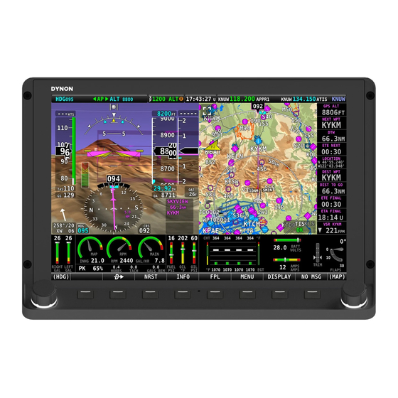
Page 268: Display Bezel Layout
Each SkyView display has an integrated light sensor in the bezel. This light sensor can be used for automatic backlight level management. Reference the Display Setup Section of this manual for instructions on how to configure the display for automatic backlight level management. SkyView HDX System Installation Manual - Revision E 21-2... -
Page 269: Joystick And Button Operation
21.3.1 Operation Basics SkyView HDX knobs do not move (click) up, down, left, or right – they only rotate clockwise and counter-clockwise. SkyView HDX knobs incorporate a pushbutton function. Figure 121: SkyView HDX Knob Rotation and Pushbutton Action A keypad button has a function if there is a label above it. -
Page 270: Menu Navigation
Display Operation Figure 123: Adjusting Successive Characters in SkyView HDX When the parameter is first displayed, the most significant (left-most) field is highlighted. Rotate the knob clockwise to increment the parameter, or counter-clockwise to decrement the parameter. In this example, the first time you rotate the knob, you toggle between the “-“... -
Page 271: Display Operation Procedures
STAY ON and PWR OFF at the bottom of the screen. Press PWR OFF to turn off the SkyView display immediately. Press STAY ON to keep the SkyView display on via the connected SV-BAT-320. If STAY ON is pressed, the display will SkyView HDX System Installation Manual - Revision E 21-5... -
Page 272: How To Reboot The Display
For example, knob or joystick 1 could be set to adjust the Heading bug and knob or joystick 2 could be set to adjust the Altitude bug. If you have a SkyView HDX display, push the knob (pushbutton) to enter its Function Menu. Figure 3-5 illustrates the Joystick / Knob menu. -
Page 273: How To Enter The Setup Menus
• ENTER FULL SCREEN SETUP MENU. Note that this menu occupies only half of the screen and that all the links in the In-Flight Setup Menu are accessible via the SETUP MENU. SkyView HDX System Installation Manual - Revision E 21-7... -
Page 274: Setup Menu
220 or SV-XPNDR-261. 21.6.2 SYSTEM EVENT Menu The SYSTEM EVENT menu will only appear if the SkyView display detects that a “system event” has occurred on (one (1) of your) SkyView display(s). SkyView HDX System Installation Manual - Revision E 21-8... -
Page 275: System Software Menu
• EXPORT SETTINGS – Use this wizard to export the settings on your SkyView system to a USB flash drive. Note that (as of V6.0) calibration settings are not exported, including servo calibrations, fuel tank calibrations, and compass calibrations. SkyView HDX System Installation Manual - Revision E 21-9... -
Page 276: System Setup Menu
Waypoints that are currently stored in your SkyView system. • EXPORT DYNON DIAGNOSTIC FILE – This specialized data log can only be interpreted by Dynon Avionics personnel; there is no data in it that can be interpreted by SkyView pilots. Dynon Avionics Technical Support may request this log during troubleshooting, especially for issues related to AP performance. -
Page 277: Local Display Setup Menu
A compatible external control signal is required for external backlight control. Refer to the Brightness Setup Section for more information. • TOP BAR SETUP – Configures the top bar on the SkyView display's screen. SkyView HDX System Installation Manual - Revision E 21-11... -
Page 278: Pfd Setup Menu
• EXTREME PITCH WARNING – Enter this page to enable/disable display of the extreme pitch warning indicators. • ANGLE OF ATTACK – Enter this page to enable/disable display of the Angle of Attack indicator. SkyView HDX System Installation Manual - Revision E 21-12... -
Page 279: Ems Setup Menu
• ENGINE INFORMATION – Set important information regarding the engine in your aircraft such as engine type and horsepower. The user-entered information here is used to calculate quantities such as % power and special operating limitations. SkyView HDX System Installation Manual - Revision E 21-13... -
Page 280: Map Setup Menu
• STATUS – Displays diagnostic / troubleshooting information for the AP system. • AUTOPILOT CONTROLS – Chooses the EXPERT or SIMPLIFIED mode. Note that the EXPERT mode must be selected for the Dynon Avionics SV-AP- PANEL to be active. • ROLL AXIS – Roll axis setup and tuning parameters. -
Page 281: Transponder Setup Menu
Reference the Section of this manual for more details. • TRIM MOTOR CONFIGURATION – Enter this menu to configure one (1) or two (2) trim motors (connected to / powered by the Dynon Avionics SV-AP- PANEL 15-pin connector) for automatic trim control (Autopilot Auto-trim) during AP operation. -
Page 282: How To Update Software
A 1 GB or 2 GB USB flash drive will be adequate. Dynon Avionics recommends the use of “name brand” USB flash drives – “house brand” USB flash drives can sometimes fail prematurely, causing corrupted files or lost data. -
Page 283: How To Export System Settings
1. Insert the USB flash drive into one (1) of the display’s USB sockets. 2. Go to the Export Settings Wizard (SETUP MENU > SYSTEM SOFTWARE > EXPORT SETTINGS…). 3. Create a file name for the settings file. SkyView HDX System Installation Manual - Revision E 21-17... -
Page 284: How To Load And Delete Files
Note that this log is very big – over 500 MB – and takes minutes to save to a USB flash drive. Unless directed to export this log by Dynon Avionics, there is no reason to do so. This file is too large to send in an email message. -
Page 285: Navigation Mapping Setup
Available for free for US SkyView pilots from Dynon Avionics. Jeppesen and PocketFMS data available for all other SkyView pilots worldwide. • Obstacles data: Available for free for US SkyView pilots from Dynon Avionics. Jeppesen and PocketFMS data available for all other SkyView pilots worldwide. -
Page 286: Viewing Information About Installed Databases
128. Note that in a SkyView system with multiple displays, it is possible for each display to have different, and different versions (expiration dates) of various databases. Thus, when verifying the presence, and expiration dates, of databases, check them on each SkyView display. SkyView HDX System Installation Manual - Revision E 22-2... - Page 287 Navigation Mapping Setup Figure 127: SkyView Database Expired Popup Message Figure 128: Aviation Database Expired Caution Message (Lower Left Corner of Display) SkyView HDX System Installation Manual - Revision E 22-3...
-
Page 288: Terrain Database
SkyView uses high resolution terrain databases to display the base topographic map on the MAP page, as well as to display Synthetic Vision on the PFD page. The Skyview HDX displays are shipped with terrain databases for North America (includes the continental United States, part of Alaska, most of Canada, Mexico, part of Central America, and the West Indies). -
Page 289: Aviation/Obstacle Databases
SkyView to provide detailed information about aviation features. SkyView can also provide navigation to these aviation features. 22.2.3.1 Free Dynon Avionics Aviation and Obstacle Data (U.S. Only) Aviation and Obstacle data is available free-of-charge for US SkyView pilots. Go to http://www.dynoncertified.com/us-aviation-obstacle-data.php... -
Page 290: Stadium Tfr Database (U.s. Only)
22.2.4 Stadium TFR Database (U.S. Only) Dynon Avionics includes a Stadium TFR database as part of its “Quick Packages” for US pilots. In loading any “Quick Package” since then, the Stadium TFR database will be loaded onto a SkyView system. After the Stadium TFR database is loaded, a TFR will be displayed on the MAP PG as if it was being received via ADS-B. -
Page 291: Base Map (Cultural Data)
Jeppesen, or PocketFMS. a. If you’ve downloaded data from the Dynon Avionics website or PocketFMS: Copy the file onto your USB flash drive. The file must be in the root directory of the drive in order to be recognizable by the display b. -
Page 292: Removing Databases
SETUP > INSTALLED DATABASES. Highlight the database you wish to remove, and then press the REMOVE button. Aviation Data updates are published periodically by Dynon Avionics, PocketFMS, and Jeppesen. It is the user’s responsibility stay current with these updates and keep their equipment up to date. -
Page 293: Appendix A: Maintenance And Troubleshooting
Dynon Avionics SkyView pilots to discuss installation and operational issues relating to Dynon Avionics products. The Forum is especially useful for pilots with uncommon aircraft or unusual installation issues. For SkyView pilots that cannot call Dynon Avionics Technical Support during our normal business hours, the Forum is a convenient way to interact with Dynon Avionics Technical Support. -
Page 294: Saving A Screenshot Of A Specific Screen
Appendix A: Maintenance and Troubleshooting 23.2 Saving a Screenshot of a Specific Screen It is sometimes helpful to have a screenshot of a behavior to share with Dynon Avionics Technical Support. Screenshots recorded with this method are far superior to photos because they are always “in focus”... -
Page 295: Skyview Displays Error: Sys Event 5: See Setup
Appendix A: Maintenance and Troubleshooting • This file is too large to send in an email message. If Dynon Avionics Technical Support has requested that you send a Dynon Diagnostic File, go to http://www.dynonavionics.com/docs/upload.html to transmit the file to Dynon Avionics. -
Page 296: Returning Skyview Components To Service After Repair
23.6.1 SkyView Display Scenario 1 When the documentation furnished with the repaired display indicates that is being returned to you with the exact same settings/configuration as it was sent to Dynon Avionics with 1. In this case, the display contains EXACTLY the same configuration as it did when you sent it in. -
Page 297: Skyview Display Scenario 3
Load the EXPORT SETTINGS file via SETUP MENU > SYSTEM SOFTWARE > LOAD FILES. b. Confirm that the tail number under SYSTEM SETUP > AIRCRAFT INFORMATION is now set to the actual aircraft tail number, not DYNON. TAIL NUMBER should not include dashes (-) or spaces. Examples: Correct: N12AB Incorrect: N-12AB or N 12AB c. -
Page 298: Multi-Display Skyview System, Continuing To Fly With A Missing Display
NEVER the newly repaired display. If network configuration is done from the repaired display, it is possible for it to overwrite the correct settings that are stored in your good display with the Dynon Avionics default factory settings. -
Page 299: Adahrs-200 Module
ADAHRS. 6. If the ADAHRS is the same serial number as the ADAHRS you returned for repair, no further actions should be required. However, Dynon Avionics recommends double checking the performance of compass and AOA calibration. If these do not seem to work as well as they previously did, redo those calibrations. -
Page 300: All Other Skyview Network Components
• Serial port status and current baud rate. • Button and joystick states. • Operational hours. 23.8.1 Display Serial Number The serial number of the display is noted here as SERIAL NUMBER: XXXXXX. SkyView HDX System Installation Manual - Revision E 23-8... -
Page 301: Display Software Version
The screen's brightness level is shown here as a percent. For example, 100.0 means 100% and 50.0 means 50%. 23.8.8 Local Light Sensor Output Each SkyView display has an integrated light sensor on the front bezel and its output is shown here. SkyView HDX System Installation Manual - Revision E 23-9... -
Page 302: External Light Control Signal Output
Pitot / Static system test - refer to “Performing Pitot/Static Checks” near the end of the SV-ADAHRS-200 Installation and Configuration section. • Annually test the SV-BAT-320 Backup Battery. • Annually perform a ZERO PRESSURE IAS/AOA CALIBRATION. SkyView HDX System Installation Manual - Revision E 23-10... -
Page 303: Annual Sv-Bat-320 Test
Figure 133: BATTERY TEST NEEDED message If your SkyView system has more than one (1) SkyView display with an SV-BAT-320 installed, perform the following test individually on each SkyView display / SV-BAT-320. SkyView HDX System Installation Manual - Revision E 23-11... - Page 304 BAT-320 must be returned (at customer’s expense) to Dynon Avionics to avoid being charged full purchase price of a new SV-BAT-320. If a SV-BAT-320 does not pass an annual test, and it is still within warranty, contact Dynon Avionics Technical Support (contact information at the beginning of this manual) for...
-
Page 305: Troubleshooting
If a SV-BAT-320 does not pass an annual test, and is no longer within warranty, dispose of the used SV-BAT-320 (see below) and purchase a new SV-BAT-320 from Dynon Avionics or a Dynon Avionics dealer. An SV-BAT-320 cannot be repaired or rebuilt. -
Page 306: Skyview Reports Standby Network Error
If you try to calibrate your compass and it does not work, try the following: • Ensure SkyView is receiving data from the system’s GPS receiver – a message: VALID GPS SIGNAL REQUIRED TO CALIBRATE COMPASS will appear if GPS data is not available. SkyView HDX System Installation Manual - Revision E 23-14... -
Page 307: Display Does Not Turn On
Green light flashing: Normal when display is turned on, or turned off with a SV-BAT-320 connected. o Green light solid on or off: Something is wrong with the SkyView display. Contact Dynon Avionics Technical Support (contact information at the beginning of this manual) for further support. 23.10.5 No GPS GPS is an essential part of a SkyView system. -
Page 308: Engine Sensor Does Not Show Up Onscreen
Engine Sensor Does Not Show Up Onscreen Make sure the sensor is installed, defined, mapped, and configured according to the instructions found in Section 10 SV-EMS-220 Engine Monitoring System Installation and Configuration. SkyView HDX System Installation Manual - Revision E 23-16... -
Page 309: Appendix B: Specifications
0.70 lb. (0.32 kg) SV-NET-SPL 0.20 lb. (0.09 kg) Single sensor / accessory. Multiply by the number for total weight of sensors / accessories. 24.2 SkyView Compatible Engine Sensors (sold by Dynon Avionics) Table 51: SkyView Compatible Engine Sensors Dynon Avionics Description Range/Type... - Page 310 1/8-27 NPT 503388-000 Oil Temperature (for Lycoming/ -10° F to 300° F 5/8-18 UNF 503385-000 Continental/Superior) Oil Temperature (for older Continental 0- -10° F to 300° F 1/8-27 NPT 100409-000 200s) SkyView HDX System Installation Manual - Revision E 24-2...
-
Page 311: Bat-320 Specifications
Protection from short circuit? Protection from over-current? Safe to be shipped? Air – IATA SV-BAT-320 has minimal lithium Sea – IMDG content, below threshold(s) Road – ADR considered to be dangerous. Rail – RID SkyView HDX System Installation Manual - Revision E 24-3... -
Page 312: Xpndr-261 Specifications
Transmitter Modulation 6M75 V1D Receiver Frequency 1030 MHz Receiver Sensitivity -74Dbm ± 3Db Physical Specifications (in the mounting tray) 48mm (1.9”) Height 66mm (2.5”) Width 160mm (6.3”) Length Weight 0.77lbs. (350 g) SkyView HDX System Installation Manual - Revision E 24-4... -
Page 313: Xpndr-261 Ads-B Information
Analysis of the system latency should add this to the latency of the GPS system and the transmission time of the position data from the GPS to the transponder to determine the overall latency. SkyView HDX System Installation Manual - Revision E 24-5... -
Page 314: Cfr § 91.227 Compliance
Appendix B: Specifications 24.6.1 14 CFR § 91.227 Compliance The Dynon Avionics SV-XPNDR-261 transponder can be connected to the following GPS units to form the basis of a 14 CFR § 91.227 compliant ADS-B Out installation: • Dynon Avionics SV-GPS-2020 (connected to SkyView display). - Page 315 < 6dB variation 5 µV to 100 mV EMF Maximum VSWR 2.5:1 or lower Physical Specifications (in the mounting tray) Height 48mm (1.9”) Height Width 66mm (2.5”) Width Length 160mm (6.3”) Length SkyView HDX System Installation Manual - Revision E 24-7...
-
Page 316: Com-T8 Environmental Qualification Form
Equipment identified as Category X – no test required Icing 24.0 Equipment identified as Category X – no test required Electrostatic Discharge 25.0 Fire, Flammability 26.0 Equipment identified as Category C SkyView HDX System Installation Manual - Revision E 24-8... -
Page 317: Gps-2020 Specifications
7 oz. (198g) 8V, 0.1A (Orange Wire +) Power Requirements Electrical Ground (Black Wire -) Operating Temperature -4°F to +158°F (-20°C to +70°C) Storage Temperature -40°F to +140°F (-40°C to +60°C) SkyView HDX System Installation Manual - Revision E 24-9... -
Page 319: Appendix C: Wiring And Electrical Connections
Other grounding recommendations include: • Ensure that solid, thick electrical connections exist between engine and battery ground. • Do not paint over surfaces that are ground connection points. SkyView HDX System Installation Manual - Revision E 25-1... -
Page 320: Dsub Crimp Contacts And Tools
Appendix C: Wiring and Electrical Connections 25.3 DSUB Crimp Contacts and Tools DSUB crimp contacts can be obtained from a variety of sources. Dynon Avionics recommends the use of the following Mil Spec types in avionics applications. Table 58: Recommended DSUB Crimp Pins... - Page 321 25.4.2 USB Cable (from D37 connector) The USB cable used in the SV-HARNESS-D37 is a unique part made to Dynon Avionics’ specifications for this application and is not sold separately. Attempting to terminate a typical USB cable to a “DSUB” connector causes the USB device to perform marginally (in our experience).
-
Page 322: Skyview Equipment Electrical Connections
• One (1) standard 8-pin RJ45 connector for use with twisted pair Category 5 Ethernet cable. Figure 136: SkyView Display Connectors A SkyView ADAHRS module (SV-ADAHRS-200/201) has two (2) connectors as illustrated in Figure 137: SkyView HDX System Installation Manual - Revision E 25-4... -
Page 323: Skyview Equipment Electrical Connector Pinout Tables
25.6 SkyView Equipment Electrical Connector Pinout Tables See tables on the follow pages for connector pin function descriptions. Tables for the USB jacks, RJ45 jack, OAT connector, and battery connector are not included. SkyView HDX System Installation Manual - Revision E 25-5... -
Page 324: Servo Pinout (Sv-Net-Servo)
25.6.1 Servo Pinout (SV-NET-SERVO) Figure 139: SV-NET-SERVO D9F Connector Pin Numbering Dynon Avionics servos (SV32, SV42) use a D9M connector (included with the SV-NET- SERVO harness). Figure 139: SV-NET-SERVO D9F Connector Pin Numbering above shows the pin numbering for the servo’s D9M connector, from the rear (pin insertion) view. -
Page 325: Skyview Display D37 Pinout (Sv-Harness-D37)
Blue with Violet stripe Serial Port 4 RX Blue with Orange stripe Serial Port 4 TX Gray with Violet stripe Serial Port 5 RX Gray with Orange stripe Serial Port 5 TX SkyView HDX System Installation Manual - Revision E 25-7... - Page 326 Do Not Connect Do Not Connect Do Not Connect Do Not Connect Do Not Connect Do Not Connect Do Not Connect Do Not Connect Do Not Connect Do Not Connect Do Not Connect SkyView HDX System Installation Manual - Revision E 25-8...
-
Page 327: Skyview D37M Block Diagram
Appendix C: Wiring and Electrical Connections 25.6.3 SkyView D37M Block Diagram Figure 141 below illustrates basic SkyView display D37 electrical connections. Figure 141: SkyView Display’s D37M Connector Electrical Connections SkyView HDX System Installation Manual - Revision E 25-9... - Page 328 SkyView Network Data 1 B SkyView Network Power 1 White with Green SkyView Network Data 2 A stripe White with Red SkyView Network Power 2 stripe Figure 142: SkyView Network D9M Pin Insertion View (Rear) SkyView HDX System Installation Manual - Revision E 25-10...
-
Page 329: Ems-220 Pinouts (Ems Harnesses)
Enhanced General Purpose Input 3 Orange/Green Amps+ Input Orange/Violet Amps- Input Green/Red Manifold Pressure Input Open General Purpose TC Input 1+ Open General Purpose TC Input 1- Yellow/Green Optional External Alarm Indicator Black Signal Ground SkyView HDX System Installation Manual - Revision E 25-11... - Page 330 Orange/Green Amps+ Input Orange/Violet Amps- Input Green/Red Manifold Pressure Input RPM Signal to Rotax 912 iS Prop Controller Open (optional) NOTE: Must be grounded to common Open ground with Prop Controller SkyView HDX System Installation Manual - Revision E 25-12...
- Page 331 CHT2 RED EGT2 RED CHT1 RED EGT1 RED White CHT6 WHITE Yellow EGT6 YELLOW White CHT5 WHITE Yellow EGT5 YELLOW White CHT4 WHITE Yellow EGT4 YELLOW White CHT3 WHITE Yellow EGT3 YELLOW SkyView HDX System Installation Manual - Revision E 25-13...
-
Page 332: Arinc-429 Pinout
Pins 12/13 are the same TX signal. Provided for (determined by ARINC TX B convenience when connecting multiple ARINC installer) receivers. No Connect No Connect No Connect No Connect No Connect No Connect SkyView HDX System Installation Manual - Revision E 25-14... -
Page 333: Xpndr-261 Pinout (Sv-Harness-Xpndr)
Data Output to SkyView Black Ground Connect to Aircraft Ground No Connect No Connect No Connect No Connect No Connect 25.6.7 SV-XPNDR-261 Pinout (SV-HARNESS-XPNDR) Figure 147: SV-XPNDR-261 D25M Connector Pin Numbering SkyView HDX System Installation Manual - Revision E 25-15... -
Page 334: Ap-Panel Pinout (D15M Connector)
Figure 148 above shows the pin numbering for the mating D15F connector, installed on the cable that plugs into this connector, from the rear (pin insertion) view. SkyView HDX System Installation Manual - Revision E 25-16... -
Page 335: Com-Panel Pinout (D15M)
The SV-COM-PANEL-uses a D15M connector for connecting to the SV-COM-T8 COM radio module. Figure 149 above shows the pin numbering for the mating D15F connector, installed on the cable that plugs into this connector, from the rear (pin insertion) view. SkyView HDX System Installation Manual - Revision E 25-17... -
Page 336: Com-T8 Pinout
The SV-COM-T8 uses a D25M connector for connecting to the SV-COM-PANEL. Figure 150 above shows the pin numbering for the mating D25F connector, installed on the cable that plugs into this connector, from the rear (pin insertion) view. SkyView HDX System Installation Manual - Revision E 25-18... - Page 337 No Connection (determined by GROUND IN GROUND installer) (determined by MICROPHONE IN installer) (determined by POWER IN 10-30V DC @ 5A installer) (determined by POWER IN 10-30V DC @ 5A installer) SkyView HDX System Installation Manual - Revision E 25-19...
-
Page 339: Appendix D: Sv-Ems-220 Sensor Input Mapping Worksheet
C37 P12 C37 P14 C37 P19 C37 P20 C37 P21 C37 P22 C37 P23 C37 P24/25 C37 P26 C37 P27/28 C37 P31 C37 P32/34 C37 P33/35 C37 P36/37 C25 P2/14 C25 P3/15 SkyView HDX System Installation Manual - Revision E 26-1... - Page 340 Appendix D: SV-EMS-220 Sensor Input Mapping Worksheet Function Sensor Name C25 P4/16 C25 P5/17 C25 P6/18 C25 P7/19 C25 P8/20 C25 P9/21 C25 P10/22 C25 P11/23 C25 P12/24 C25 P13/25 SkyView HDX System Installation Manual - Revision E 26-2...
-
Page 341: Appendix E: Serial Data Output
DYNON EMS, ADAHRS, DYNON SYSTEM, DYNON ADAHRS + SYSTEM, DYNON ADAHRS + EMS, or DYNON ADAHRS + SYS + EMS, NMEA OUT (BASIC), or NMEA OUT (FULL) as a Serial Out device, select a baud rate, and connect the serial port to an external serial device such as a PC. -
Page 342: Dynon Adahrs Serial Data Format
Appendix E: Serial Data Output 27.1 DYNON ADAHRS Serial Data Format The following section details the format of DYNON ADAHRS serial output data: Table 78: SkyView ADAHRS Serial Data Output Format Position Width Name Description Start Character / Data Type 1 = ADAHRS data. -
Page 343: Dynon System Serial Data Format
Checksum hexformat, so 3A = 0x3A CR/LF Carriage Return, Linefeed = 0x0D, 0x0A. As an example, the following is one (1) line of DYNON ADAHRS serial output data: !1121144703-014+00003310811+01736+003-03+1013- 033+110831245+01650023176C 27.2 DYNON SYSTEM Serial Data Format The following section details the format of DYNON SYSTEM serial output data:... - Page 344 0 or 1. 0 = No slipping on this servo. 1 = At least one AP Pitch Slip (bool) (1) slip on this servo in the last 3 seconds. Always reads zero when AP pitch not engaged. SkyView HDX System Installation Manual - Revision E 27-4...
- Page 345 The 1 byte sum of all 73 preceding bytes. In 27-5sci- Checksum hexformat, so 3A = 0x3A CR/LF Carriage Return, Linefeed = 0x0D, 0x0A. As an example, the following is one (1) line of DYNON SYSTEM serial output data: !2221144704359XXXXX1600+010XXX00XXXXXXXX00X0X+00- 99990+00+99990+00XXXXX00104543XXXXXXXXXX3A SkyView HDX System Installation Manual - Revision E 27-5...
-
Page 346: Dynon Ems Serial Data Format
There must be a Level sensor named “LEFT” for Fuel Level L Varies this to work. If there is no “LEFT” OR “RIGHT” (gal) but there is a “MAIN”, this will be MAIN. See note 2. SkyView HDX System Installation Manual - Revision E 27-6... - Page 347 +/- then 000 to 999. In degrees C. See note 2. 14 (deg C) +/- then 0000 to 9999, then units. See notes. GP Input 1 C37 P4 Example: +1234C = 123.4 degrees C. SkyView HDX System Installation Manual - Revision E 27-7...
- Page 348 Rotax 912 iS Note: When the engine type is 912iS, the following fields in the serial output source their data from the 912 iS’ computer instead of conventional sensors: Oil Pressure, Oil Temp, RPM L, RPM R, Manifold Pressure, Fuel Flow 1, Fuel Flow 2 (always 0). SkyView HDX System Installation Manual - Revision E 27-8...
- Page 349 • If flaps, this is the angle shown on the screen, so 0038 = 38 degrees • XXXX if the signal is out of range or not calibrated (red X on ems page) • ZZZZ if the input is not configured SkyView HDX System Installation Manual - Revision E 27-9...
-
Page 350: Dynon Adahrs / System / Ems Serial Data Output Combinations
Appendix E: Serial Data Output As an example, the following is one (1) line of DYNON EMS serial output data: !3221144705060+09323632363272057057164263263000280280+1200001300020+19 7+592+197+592+197+592+197+592+197+592+197+592+197+197- 0012T+0013T+0001T+0164P+1990P+0928C+0001T+0000G+0263G+0263G+0599P+0 928C+0928CZZZZZZZZZZZZZZZZ045L26 27.4 DYNON ADAHRS / SYSTEM / EMS Serial Data Output Combinations 27.4.1 DYNON ADAHRS + SYSTEM Serial Data Format DYNON ADAHRS+SYSTEM output data alternates between DYNON ADAHRS data and DYNON SYSTEM data. -
Page 351: Nmea Out Serial Data Formats
GPS navigators generate. For example, the following is one (1) cycle of NMEA OUT (FULL) serial output data: $GPGGA,221755,3157.4430,N,00000.0000,E,1,04,1.30,3000.0,M,33.9,M,,0000*66 $GPGSA,A,3,01,02,03,04,00,00,00,00,00,00,00,00,1.00,1.30,1.40*00 $GPGSV,1,1,04,01,20,100,10,02,30,200,56,03,45,300,32,04,62,045,05*7A $GPRMC,221755,A,3157.4430,N,00000.0000,E,82.07,1.00,300811,0.49,W,A*06 $GPVTG,1.00,T,0.49,M,82.07,N,151.99,K,A*17 $GPRMB,A,9.99,L,FHAW,TUPJ,1826.7333,N,06432.4998,W,999.9,273.6,005.1,V,A*41 $GPGLL,3157.4430,N,00000.0000,E,221755,A,A*42 $GPBWC,221755,1826.7333,N,06432.4998,W,273.6,T,274.1,M,999.9,N,TUPJ,A*67 $GPXTE,A,A,9.99,L,N,A*0A $GPBOD,299.3,T,299.8,M,TUPJ,FHAW*4F $GPAPB,A,A,9.99,L,N,V,V,299.8,M,TUPJ,274.1,M,274.1,M,A*4E SkyView HDX System Installation Manual - Revision E 27-11... -
Page 353: Appendix F: User Data Logs
EMS input follow the following format: Name (Units) (where the “Name” field is as it is named in the SENSOR INPUT MAPPING setup menu). Each row beneath that header row contains an individual record – or instantaneous snapshot SkyView HDX System Installation Manual - Revision E 28-1... -
Page 354: Recent Flight Data Log
The Recent Flight Data Log records data whenever SkyView believes that it is in flight, which it determines by observing IAS and/or GPS ground speed. 28.1.3 Alert Data Log Filename format: DATE-TAILNUMBER-SKYVIEWDISPLAYSERIALNUMBER-SOFTWAREVERSION- OPTIONAL33CHARACTERS-ALERT_DATA.csv Example: 2014-08-07-N123X-SN1492-11.0-CROSS_COUNTRY_LEG1-ALERT_DATA.csv SkyView HDX System Installation Manual - Revision E 28-2... -
Page 355: History Data Log
(CROSS_COUNTRY_LEG1 is user-selectable text, up to 33 characters, at time of export.) The History Data Log is a cumulative history of files loaded onto the SkyView and other changes mostly used for troubleshooting when requested from Dynon Avionics Technical Support. 28.1.5 Data Logging Recording Options 28.1.5.1... -
Page 356: Exporting Data Logs
Data Logs. Instructions for creating an account and uploading data logs are on the Savvy Analysis website. Other than technical cooperation to ensure that SkyView data logs can be correctly parsed as formats are periodically updated, Dynon Avionics has no relationship with Savvy Analysis. SkyView HDX System Installation Manual - Revision E... -
Page 357: Appendix G: Sensor Debug Data
(2) displays and update one (1) display (load a new SFG file) so that both displays have the same File Version. “HeartBeat” – Increments steadily as data is received from the SV-EMS-220(s). “Resistor Control” – Status of the “pull up resistors” in the SV-EMS-220(s); Dynon Avionics internal use only. Columns: •... - Page 358 • SENSOR ID – The type of sensor selected in SENSOR INPUT MAPPING for this sensor / input / pin. • RAW – Raw number from the Analog to Digital converter; Dynon Avionics internal use only. • CAL(V) – The exact voltage that is present on this pin. The output of many sensors is converted to a voltage in the SV-EMS-220 for processing.
- Page 359 Vref+ is an internal calibration voltage. If it's not near 5.00V in CAL(V) something in the voltage regulator circuitry is not operating correctly and will likely not read correctly. Vdiff: Value should be near 100. This only affects thermocouples. SkyView HDX System Installation Manual - Revision E 29-7...
- Page 360 0diff: VALUE should be near 0.4. This only affects thermocouples. ColdJ: Cold junction, which is the temp of the EMS box. VALUE should be the temp of the EMS box in degrees F. This only affects thermocouples. SkyView HDX System Installation Manual - Revision E 29-8...
-
Page 361: Appendix H: Checklists
CHECKLIST, such as CHECKLIST01.txt, CHECKLIST02.txt, etc. This will allow all of your Checklist files to be grouped together and all Checklists easily seen on your USB flash drive when you are loading the Checklist into your SkyView display. SkyView HDX System Installation Manual - Revision E 30-1... -
Page 362: Saving Your Checklist With "Utf-8 Character Encoding
8. Under Plain Text File Encoding, pull down the Saving Files: menu. 9. Click on Unicode (UTF-8). 10. Unicode (UTF-8) should now be checked. 11. Click on the Red button to close Preferences. SkyView HDX System Installation Manual - Revision E 30-2... - Page 363 4. File Name: (fill in your preferred filename for your Checklist file). 5. Save as type: Text Documents (*.txt). 6. Encoding: Pull down and select UTF-8. 7. Click the Save button. Steps 4-7 are illustrated in Figure 155 below: SkyView HDX System Installation Manual - Revision E 30-3...
-
Page 364: Example Checklist
# LINES ARE 40 CHARACTERS LONG ON A SKYVIEW 50 PERCENT PAGE # LINES WITH MORE CHARACTERS THAN ABOVE ARE NOT WRAPPED AND WILL SHOW # SV_Checklist_Template_Rev_A.txt CHKLST0.TITLE, PRE-FLIGHT CHKLST0.LINE1, CHKLST0.LINE2, BUILD YOUR CHECKLIST HERE SkyView HDX System Installation Manual - Revision E 30-4... -
Page 365: Example Checklist Formatting Notes
Each Checklist requires a title line in this format: CHKLST(section number).TITLE, (title). Example: CHKLST0.TITLE, PRE-FLIGHT Each Checklist can have any number of Checklist items (including none), but each item must be sequentially numbered, beginning from 1, in this format: SkyView HDX System Installation Manual - Revision E 30-5... -
Page 366: Excel Checklist Generation Tool
(DATE MUST BE MANUALLY UPDATED) 30.4 Excel Checklist Generation Tool Dynon Avionics has developed a SkyView Checklist Generation Tool based on Excel for Mac or PC; this tool will not work in the versions of Excel accessible online or in versions of Excel on tablet devices (these versions do not have “macro”... -
Page 367: Loading A Checklist
Appendix H: Checklists a video tutorial for this tool, available on the Dynon Avionics Channel section of YouTube – https://www.youtube.com/user/Dynon Avionics. 30.5 Loading a Checklist After you have saved your Checklist file from your computer to your USB flash drive, take the USB flash drive to your aircraft. - Page 368 Encoding, or Figure 152, Figure 153, and Figure 154 above for Mac OS TextEdit. If your Checklist will still not load, then, check that each section (each individual Checklist) begins with the same CHECKLIST(number). Example: SkyView HDX System Installation Manual - Revision E 30-8...
-
Page 369: Displaying Your Checklist On Your Skyview Display
SkyView system to Software v14.0. To access your Checklist on a SkyView display, from the main menu, go to the TOOLS menu and push the CHECKLIST button. The Checklist will continue to be displayed until SkyView HDX System Installation Manual - Revision E 30-9... - Page 370 • If the display is set to display MAP and EMS (any % of either), the EMS page will be resized to 50% and the Checklist will be displayed at 50%. Figure 158: List of Checklists Available SkyView HDX System Installation Manual - Revision E 30-10...
- Page 371 Figure 159: Example Pre-Flight Checklist The Checklist will continue to be displayed until the CHECKLIST button is pressed again (the CHECKLIST button “toggles” the display of your Checklist On and Off). SkyView HDX System Installation Manual - Revision E 30-11...
-
Page 373: Appendix I: Switches, Controls, Etc. External To Skyview Units
(PBNO); do not connect to a button if using SV-INTERCOM- 2S or other audio panel. SV-EMS-220 Warning Yellow/Gre Indicator. Indicator SV-XPNDR-261 Standby Single Pole Single Throw (SPST) Switch. Ident Pushbutton Push Button Normally Open (PBNO). SkyView HDX System Installation Manual - Revision E 31-1... - Page 374 Appendix I: Switches, Controls, Etc. External to SkyView Units SkyView HDX System Installation Manual - Revision E 31-2...
Need help?
Do you have a question about the SkyView HDX and is the answer not in the manual?
Questions and answers