Advertisement
Quick Links
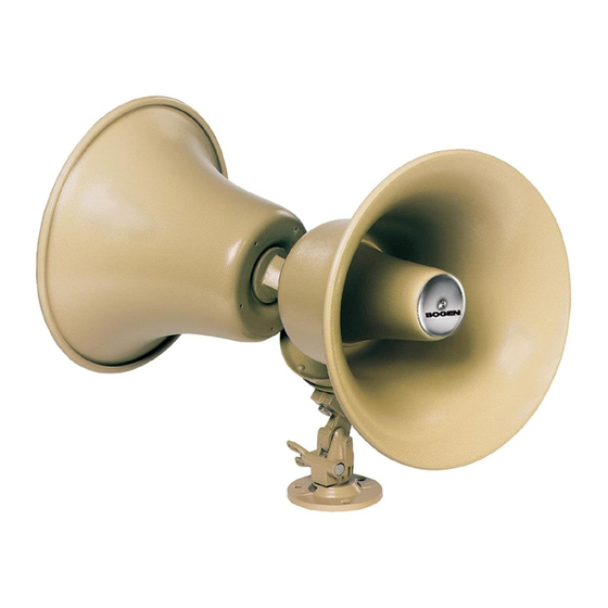
Bi-Directional Reentrant
Horn Loudspeaker
Speaker Assembly
The bi-directional speaker must be assembled prior to installation. See Figure 3 on the back of this sheet for speaker assembly
information. Make sure to place the washer/seals where indicated and hand tighten the various components - do not use pliers
or similar tools.
Speaker Installation
STEP 1 - For easier installation, remove the flange (base) from the speak-
er by unscrewing the wing nut while at the same time pressing inwardly on
the wing nut. Place the flange flush with the mounting surface and mark the
location of the three holes with either a marker or punch. It is important
that the three holes be exactly aligned with the flange, otherwise you might
stress the base or make the connection unsteady (see Figure 1).
NOTE: Speaker may also be strap-mounted through the slot in flange (base)
using standard 1/2-inch industrial strapping (not included).
STEP 2 - After mounting the flange, reattach the speaker to the flange and
aim the speaker for the desired coverage. A 45
ommended, but this may vary depending upon speaker layout. Unless oth-
erwise indicated, do not aim speakers directly at each other or poor paging
intelligibility may occur.
STEP 3 - Remove the plastic cover to make the electrical connection and
set the tap set control (see Figure 2). Connect speaker wire shield to the
ground (GND) terminal of the amplifier's output. Carry the ground through
all speaker cables by tying the shields of the speaker cables together in a
"daisy chain" fashion. Do not connect the shield to the speaker itself.
The shield is only connected at the amplifier end and simply floats.
Connect wires as listed below:
Amplifier Outputs Speaker Connections
70V/25V
Terminal 1
COM
Terminal 2
NOTE: The speaker will also work perfectly well with these connections reversed.
However, reduced low frequency response may result.
STEP 4 - Adjust the tap set control to the desired setting. See table at right
for tap settings. Replace the plastic protective cover back over the exposed
area.
Frequency Response: 225Hz to 14kHz
Dimensions: 16-1/2"W x 9-3/4"H (41.9 x 24.8 cm)
Shipping Weight: 9 lbs.
Finish: Textured Mocha Enamel
Sound Pressure Level: 121dB @ four feet on axis with 30-watt input
at 1000Hz each horn
o
downward angle is rec-
Page 1 of 2
BDT30A Manual
Figure 1: Mounting Speaker Base
Figure 2
TAP SET
CONTROL
ELECTRICAL
CONNECTION
Watts (25V)
Position
.25
1
.5
2
1
3
4
1.8
5
3.7
7.5
6
7
15
8
*
*Forbidden switch settings (see text)
CAUTION
Switch settings marked with an asterisk (*) must not be
used. Failure to comply with these restrictions may cause
damage to components and will void the warranty.
Specifications subject to change without notice.
© 2000 Bogen Communications Inc. All rights reserved.
Part No. 54-5841-01r2 Printed in Korea 0003
Watts (70V)
1.8
3.7
7.5
15
30
*
*
*
Advertisement

Related Manuals for Bogen BDT30A


Summary of Contents for Bogen BDT30A
-
Page 1: Speaker Assembly
Page 1 of 2 TAP SET CONTROL ELECTRICAL CONNECTION Watts (25V) Watts (70V) CAUTION Specifications subject to change without notice. © 2000 Bogen Communications Inc. All rights reserved. Part No. 54-5841-01r2 Printed in Korea 0003... - Page 2 GREY FIBER WASHER 1-5/16" DIA BLACK RUBBER WASHER AND TIGHTEN SCREW Page 2 of 2 Figure 4: Assembled Speaker AFTER ASSEMBLY, ALIGN LOGO AND TIGHTEN SCREWS 50 Spring Street, Ramsey, New Jersey 07446 Tel. 201-934-8500, Fax: 201-934-9832 Web Site: www.bogen.com...
Need help?
Do you have a question about the BDT30A and is the answer not in the manual?
Questions and answers