Bogen HFCS1LP Installation And Use Manual
Bogen communications high-fidelity ceiling speakers installation and use manual hfcs1, hfcs1lp
Hide thumbs
Also See for HFCS1LP:
- Installation and use manual (9 pages) ,
- Specifications (2 pages) ,
- Installation and use manual (9 pages)

Related Manuals for Bogen HFCS1LP


Summary of Contents for Bogen HFCS1LP
- Page 1 High-Fidelity Ceiling Speakers Models HFCS1 and HFCS1LP Installation and Use Manual © 2006 Bogen Communications, Inc. All rights reserved. Specifications subject to change without notice. 54-2091-01C 0610...
-
Page 2: Product Description
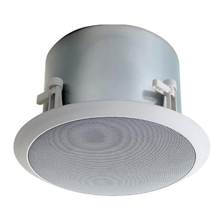
The HFCS1(LP)’s steel back can and front exit venting allow for deep bass response, enhancing the quality and intelligibility of both speech and music. The HFCS1LP uses a smaller, low-profile back can that allows for a greater range of instal- lations. -
Page 3: Product Diagrams
Front Drawing (grille removed) 1. Coaxial Driver Assembly 2. Bass Tuning Vents (x2, HFCS1, x1, HFCS1LP) 3. Grille Retention Groove 4. Power Tap Selection Switch 5. Mounting Clamp Screws (x4) Rear Drawing 6. Metal Back Can 7. Snap-Lock Input Connector 8. -
Page 4: Installation
The HFCS1 and HFCS1LP can be installed in a variety of ceiling environments. The use of the TBCR (Tile Bridge Support Ring) accessory may be desired for many of these. For suspended ceilings, the use of a TBCR is strongly recommended to help support and distribute the weight of the speaker. -
Page 5: Speaker Wiring
Eyelets are provided on the terminal covers to provide a means of securing the speaker to the structure. It is important that all 4 terminal cover screws be installed in this application. A Bogen Model CK10 cable will accomplish this. - Page 6 The front-mounted selector switch is used to set the appropriate power level or impedance for your system. Using a small, flat-blade screwdriver, turn the knob until the slot points to the power level you require. 70V/100V Systems Both power setting scales for 70V and 100V systems are labeled on the speakers.
-
Page 7: Specifications
9 lb. " dia x 12" D 11" Input Terminal Cover (2 Halves); (4) Screws; (1) Snap-Lock Input Connector Tile Bridge Support Ring (TBCR); Cable Kit (CK10) Off-white HFCS1LP 78 Hz to 19 kHz " dia. x 7- " D "... -
Page 8: Limited Warranty
In no event shall Bogen be liable for special, incidental or consequential damages (including, but not limited to, loss...
Need help?
Do you have a question about the HFCS1LP and is the answer not in the manual?
Questions and answers