Table of Contents

Subscribe to Our Youtube Channel
Related Manuals for Energie Eco


Summary of Contents for Energie Eco
- Page 1 TECHNICAL MANUAL 200esm | 250esm | 300esm 300esms 250i | 300i |250is | 300is |500is 250ix | 300ix 250isx | 300isx | 500isx Review Directives European Certification Version EN 60335-1 Date 09/01/2020 2006/95/CE EN 60335-2-21 EN 60335-2-40...
- Page 3 We would like to thank you for your choice when you acquired an equipment for sanitary water heating. The thermodynamic solar system ECO will surely meet all your expec- tations and provide many years of comfort with maximum power sav- ing.
-
Page 4: Table Of Contents
Technical Manual INDEX 1. IMPORTANT......................... 1.1. Symbols ........................1.2 Pre-installation Information ................. 1.3 Safety information ....................2.PACKAGE ........................2.1. Contents ........................2.2. Transpor ........................3.SPECIFICATIONS ......................3.1. Running principle ....................3.2. Technical features ....................3.3. Technical features ....................3.4. Main Components ....................3.4.1. - Page 5 6.1. Control Panel ......................6.2. Keys (Functions) ....................6.3. Description ........................ 6.4. Symbols ........................6.5. Operating Modes ....................6.5.1. ECO Operating Mode ................6.5.2. AUTO Operating Mode ................6.5.3. BOOST Operating Mode ................. 6.6. Extra Functions ....................... 6.6.1. DISINFECT Function ..................
-
Page 6: Important
ECO will only operate if the storage water danger sign. heater is filled with water. For a better characterization of... -
Page 7: Package
Technical Manual • Power supply to the equipment Cooling Fluid: must be disconnected when doing maintenance operations; • The cooling fluid employed in the • The supplier recommends at least whole process is R134a, CFC-free, one annual inspection to the equip- non-inflammable and without harm- ment, by a qualified technician;... -
Page 8: Transpor
Technical Manual 2.2. Transport • Transporting equip- ment must be carried out with an inclination below • The equipment must be raised and lowered with extreme care to avoid im- pact that could damage the material; • Make sure the belts and/ or transportation straps do WARNING not damage the material;... -
Page 9: Specifications
3.1. Running principle tion. After circulation in the panel, the klea is as- The thermodynamic solar system ECO, is pirated by the system’s mechanical compo- an equipment based upon the principle of nent, the compressor, which will increase its cooling by compression –... -
Page 10: Technical Features
Technical Manual 3.2. Technical features (x1 panel) Unid. 250i 300i 200esm 250esm 300esm 250ix 300ix Dry Weight Capacity Internal Protection Stain. Steel Enamelled Stain. Steel Cathodic Protection Magnesium Anode (1”1/4 Female) Water – Inlet and Outlet 3/4” Male TP Valve 1/2”... -
Page 11: Technical Features
Technical Manual 3.3. Technical features (2x panels) Unid. 250is 300is 300esms 250isx 300isx 500is 500isx Dry Weight Capacity Internal Protection Stain. Steel Enamelled Stain. Steel Cathodic Protection Magnesium Anode (1”1/4 Female) Inlet / Outlet 3/4” Male 1” Male TP Valve 1/2”... -
Page 12: Main Components
Technical Manual 3.4. Main Components 3.4.1. General diagram of assembly [1]Thermodynamic Solar Panel [2]L-shaped fastenings for attachment of Aluminium Panel [3]Set of bolt, female, washer and bushing (6x or 8x) [4]Copper pipes [5]Water storage heater [6]Thermodynamic block [7]Hood + Display [8]Bolts CHC M8 [9]Expansion tank [10]Safety device... -
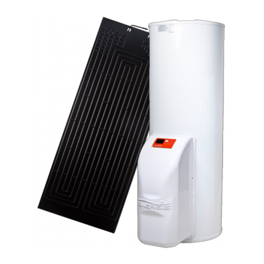
Page 13: Thermodynamic Solar Panel
Technical Manual 3.4.2. Thermodynamic Solar Panel The solar panel is a roll-bond type plate The panel has a standard dimension of manufactured in double channel pressed al- 2000 mm x 800 mm x 20 mm. uminium, with a post-press anodization-ox- idation that creates a dark tone aspect. -
Page 14: Storage Water Heater
The storage water heater has a cold water temperature probe. inlet, hot water outlet, AQS return and an outlet for the expansion valve. [14] Hood of ECO [25] Adjustable support foot [15] Condenser / Coil [26] Cold water inlet [16] “One-Shot” Female Valve [27] Recirculation [17] “One-Shot”... - Page 15 Technical Manual Seal with features [A] Model [B] Production number [C] Serial number [D] Production date [E] Volume [F] Weight [G] Downstream pressure of pressure throttle valve [H] Upstream Maximum Pressure of pressure throttle valve [I] Maximum pressure in Storage Water Heater [J] Maximum Temperature in Storage Water Heater [L] Recommended Temperature in Storage Water Heater...
- Page 16 Technical Manual Dimensions of Storage Water Heater ECO200esm / 250esm | i | ix ECO 300esm | i | ix ECO 500 i | ix...
-
Page 17: Thermodynamic Block
Technical Manual Version 250i 89mm 830mm 1333mm 1465mm 580mm 880mm 1543mm 370mm 765mm ---------- --------- 1015 300i 92mm 772mm 1172mm 1315mm 650mm 950mm 1415mm 370mm 765mm ---------- --------- 1086 200esm 91mm 830mm 1161mm 1289mm 580mm 880mm 1364mm 370mm 765mm ---------- --------- 1015 250esm... -
Page 18: Cooling Fluid
3.5.5. Dielectric Joint (except stainless steel tank) Your ECO equipment contains two dielectric joint. These joints prevent electron exchange between the pipes of water inlet and out- let and the storage water heater itself. This creates further protection against corrosion that could take place between these points (A and B). -
Page 19: Expansion Vessel
Technical Manual So the installer must tighten the joints (C) in 3.5.6. Expansion Vessel the water inlet and outlet (A and B), be fore attaching the piping (D), as demonstrated The expansion vessel is a device whose pur- in the following sequence: pose is to compensate for the increase in water volume due to temperature rise. -
Page 20: Pressure Reducing Valve
Technical Manual 4. INSTALATION The safety valve must be opened regular- ly to remove impurities and check that it is not blocked. The discharge pipe must be Assembly sequence: installed in a vertical position. • Solar panel • Storage water heater •... - Page 21 Technical Manual Attachment of L-shaped fastenings and panel: The profile should be attached to the base (e.g. rooftile) through a plastic bushing and a self-thread M6 bolt which have been sup- plied. The attachment of the panel to the L-shaped fastenings is done through M6 bolts and its females and washers.
-
Page 22: Set-Up Of The Storage Water Heater
Technical Manual 4.2. Set-up of the Storage Water b) Aim the metallic structure with the orifices to the three M8 bolts previously mentioned. Heater • Keep the equipment sheltered in places susceptible to ice crystals; • Choose the position closer to the main user points;... -
Page 23: Refrigerant Connections
Technical Manual 4.4. Refrigerant Connections cooling fluid couplings must be done by a qualified technician, with a professional certificate of qualifications for DANGER this purpose. The thermodynamic unit holds a pre-load of fluid R134a. cooling fluid couplings must be thermally insulated in order to prevent burns and to ensure an optimal system per- DANGER... -
Page 24: Connection To The Panels (X2)
Technical Manual pipe at the intended point, making sure to clean off any burrs (e.g. with a reamer). Next, remove the covers from the panel con- nections, and with the aid of a cutting tool such as a penknife, remove 5 cm of the ther- moretractable sleeve. -
Page 25: Connection Of Thermodynamic Block And Storage Water Heater
Technical Manual Thermodynamic Block, make sure the appa- ratus has been cleaned with nitrogen. For installations with two or more panels, it is essential that the fluid is homogenously dis- tributed (panel entry). The equipment already comes installed with a liquid distributor so that this process can be accurately put into effect. -
Page 26: Connection Of Thermodynamic Block And Thermodynamic Panel
Technical Manual c) Tighten with a suitable wrench, applying a torque in conformity with the diameter of the pipe employed (according to table in point 4.4.1. Insufficient torque will cause leaks of cooling fluid. Excessive torque on the coupling will damage the edge of the pipe and cause leaks. -
Page 27: Load Of Nitrogen
Technical Manual Shut Valves A – 2-Way Valve B – 3-Way Valve e) Create a vacuum with the vacuum pump plugged to the inlet of the 3-way pressure valve as depicted, keeping the valves com- pletely shut until there is a vacuum of 50 Pa (0.5mbar). -
Page 28: Load Of Complementary Cooling Fluid
Technical Manual 4.4.7. Load of Complementary 4.4.8. Checking good running Cooling Fluid condition To check whether your equipment is running The warranty does not apply to correctly, start it and wait at least 20-30 min- distances longer than what has utes and then check these conditions: been established for the pre- load (12m) -
Page 29: Electric Connections
Technical Manual 4.6. Electric Connections b) It is necessary to install a safety device at the cold water inlet of the appliance. The safety device must be in compliance To establish the electric connection of the with the standard EN 1487:2002, maximum equipment, check these conditions: pressure 7 bar (0.7 MPa);... - Page 30 Technical Manual Electric diagram (1 panel): Legend: Q1 – Differential D1 – Circuit-breaker LP – Low pressure gauge S1 – Temperature probe Comp – Compressor R1 – Resistance TB – Safety thermostat...
- Page 31 Technical Manual Electric diagram (2 panels): Legend: Q1 – Differential D1 – Circuit-breaker LP – Low pressure gauge S1 – Temperature probe Comp – Compressor R1 – Resistance RL – Relay TB – Safety thermostat...
-
Page 32: First Use
5.2. Start-up of the System Press key COMP to start-up the system Before starting the ECO, check whether the installation is set up according to the recom- mendations and that everything is in con- formity, then you may plug your equipment to the power supply. -
Page 33: System Operation
ON/OFF. 6. SYSTEM OPERATION 6.1. Control Panel The control panel of the Thermodynamic Solar system ECO is simple and intuitive. It enables the configuration of several operating parameters according to the operating mode selected by the user. It comprises six command keys (ON / OFF / CANCEL, MENU, COMP , E-HEATER ,... -
Page 34: Description
Reason for activating ter set point is reached the resistance. compressor stops, but still has the operating instruc- tion. 6.4. Symbols Equipment in ECO operating mode AUTO Equipment in AUTO operating mode Equipment in BOOST operating mode Compressor Electrical resistance Unblocked keyboard... -
Page 35: Operating Modes
Resistance (support) (E-HEATER). In these circunstances the equipment will automatically change operat- ECO comes set by default to work in the ing mode to BOOST and indicates the reason “ECO” operating mode. If the user wishes to of its activation (over the resistance). If you... -
Page 36: Extra Functions
(ECO, AUTO or BOOST). 6.6.1. DISINFECT Function If you set your equipment to en- ECO’s electronic control features the Disin- ter Holiday mode and turn it off fect function, which consists of a water heat- with the key ON/OFF, the func-... -
Page 37: System Menu
/ H02PV. Note: When the contact K1 it’s open, the equipment will assume the previous working mode (ECO, AUTO or BOOST) and its pa- rameters. The K1 contact can be used to take advan- tage of tariff with variable price. To do that, just connect a timer to the 5V/P2 contacts instead of a inverter. -
Page 38: Parameters Description
Français F01 Language English Deutsch Italiano Espanol F02 Clock Date and Time ECO mode F03 Mode Boost mode Automatic mode F04 Holidays Number of days 0 – Disinfect function inactive F05 Disinfect 1 – Disinfect function active once a week (weekly) 2 –... -
Page 39: Table Of Errors
Technical Manual 9. TABLE OF ERRORS The installation, assembly and repair of ECO can only be carried out by qualified technicians. Symbols Description Problem / Checking Damaged probe – Measure internal resistance of probe Anomaly detected which is approximately 10 KΩ at the temperature of 25 Er01 –... -
Page 40: Resolution Of Problems
Adjust the temperature of the set-point. the set-point temperature Alter the equipment to “AUTO” mode to initiate automatic management of sys- ECO mode is selected and outside tem. temperature quite low Alter the equipment to “BOOST” mode for a fast water heating. - Page 41 Technical Manual PROBLEM POSSIBLE CAUSES HOW TO PROCEED Slow running The running of the equipment depends Outside air temperature is very low of Thermo- on weather conditions. The running of the equipment depends dynamic Inlet water temperature is very low on the inlet water temperature.
-
Page 42: System Maintenance
Technical Manual 12. SYSTEM MAINTENANCE Seek advice with your installer about how you should proceed to control the anode’s condition. Before undertaking any main- tenance operation To check the condition of your anode follow equipment, make sure it is not plugged to the power supply! these steps: DANGER... -
Page 43: Empty The Storage Water Heater
Technical Manual • Remove the hood, unscrewing the four bolts; • Remove the lid (1); • Press key (2) to reactivate the thermo- stat; • Replace the lid (1) and then the hood, then screwing the four bolts. 12.5. Empty the Storage Water Heater Remember that the water in the storage water heater is at high... - Page 44 Technical Manual Warranty This warranty covers all defects to the confirmed materials, excluding the payment of any type of personal damage indemnity caused directly or indirectly by the materials. The periods indicated below start from the purchase date of the apparatus, 6 months at the latest from the leaving date from our storage warehouses.
- Page 48 Morada Zona Industrial de Laúndos, Lote 48 + 351 252 600 239 Project co-financed by: 4570-311 Laúndos - Póvoa de Varzim PORTUGAL E-mail energie@energie.pt Progetto Co-finanziato da: N 41 27.215’ , W 8 43.669’ www.energie.pt Telefone + 351 252 600 230...
Need help?
Do you have a question about the Eco and is the answer not in the manual?
Questions and answers