Table of Contents
Advertisement
Advertisement
Table of Contents

Subscribe to Our Youtube Channel
Related Manuals for Energie ECO 200i


Summary of Contents for Energie ECO 200i
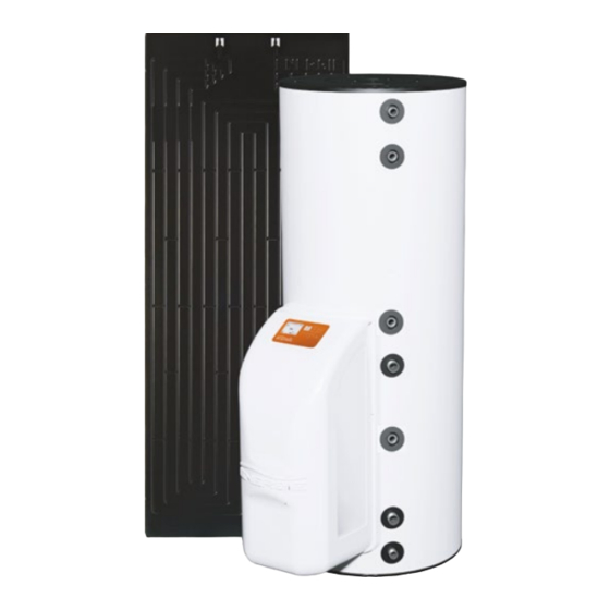
- Page 1 TECHNICAL MANUAL 200i | 250esm | 250i | 250ix | 300esm | 300i | 300ix 200is | 250is | 250isx | 300esms | 300is | 300isx | 500is | 500isx Revision 16 Directives European Certification Version 0 2006/95/CE EN 60335-1 Date 07/06/2022 EN 60335-2-21 EN 60335-2-40...
- Page 3 Technical Manual Esteemed Client, We would like to thank you for your choice when you acquired an equipment for sanitary water heating. The thermodynamic solar system ECO system will surely meet all your expectations and provide many years of comfort with maximum power saving.
- Page 4 Technical Manual Index INTRO ..................... 6 Symbols ........................6 Pre-Installation Information ..................6 Safety Information ....................6 2 PACKAGE ....................9 Contents ........................9 2.2. Transport ........................10 3 SPECIFICATIONS ................... 11 Running Principle ....................11 Techincal Features (1 panel) ..................12 Techincal Features (2 panels) ................13 Main Components ....................14 3.4.1 General Diagram of Assembly .................14...
- Page 5 Technical Manual 6 SYSTEM OPERATION ................35 Control Panel ......................35 Keys (Functions) .....................35 Interface Symbols ....................36 Operating Modes ....................36 6.4.1 ECO Operating Mode ..................37 6.4.2 AUTO Operating Mode ..................37 6.4.3 BOOST Operating Mode ..................37 Extra Modes ......................37 6.5.1 DISINFECT Function ..................37 6.5.2 VACATION Mode .....................38 6.5.3...
- Page 6 Technical Manual 1. INTRO 1.1 Symbols Every process that the supplier believes to be conducive to harmful danger and/or material damage will be signalled with a danger sign. To better characterize the danger, the symbol will be followed by one of these words: [1] DANGER: when there is the possibility of harm to the operator and/or people in the vicinity of the equipment...
-
Page 7: Technical Manual
Technical Manual Water temperature min / max in operation: 5/70 ºC; Water temperature min / max of the water heater: 5/80 ºC; WARNING DANGER When installing the safety unit, the correct direction of the hydraulic flow must be taken into account. The correct direction is represented by an arrow on the component itself. - Page 8 Technical Manual High pressure and temperature: • The principle for running this equipment is directly linked to high temperature and pressure; thus, the processes that imply contact with the equipment, must be thought out with caution to prevent the risk of burns and projection of material; Refrigerant: The refrigerant used in the entire process is R134a, CFC-free, non-inflammable and •...
- Page 9 Technical Manual 2 PACKAGE 2.1 Contents The equipment is supplied in two packages: one package for the thermodynamic solar panel with fixing elements, and the other with the thermo-accumulator and the attached thermodynamic group. The packages contain: 1. Thermodynamic solar panel with fastening elements; 2.
- Page 10 Technical Manual 2.2. Transport The equipment must be carried in an upright position. The equipment must be raised and lowered with extreme care, to avoid impact that could damage the material. Make sure the belts and/or transportation straps do not damage the material. Always use suitable means to transport the material (pallet lift, forklift, etc.) The transport of the equipment must be done with an inclination never exceeding 45º;...
-
Page 11: Specifications
Technical Manual 3 SPECIFICATIONS 3.1 Running Principle The Thermodynamic Solar System ECO is an equipment based on the principle of compression refrigeration - Carnot's principle - which we call the Thermodynamic Solar Systems: Solar Panel and a Heat Pump. The solar panel, which is the main component, placed outside ensures the capture of energy on: a) Direct and diffuse solar radiation;... - Page 12 Technical Manual 3.2 Techincal Features (1 panel) Uni. 200i 250i / esm 300i / esm 250ix 300ix Dry Weight 45 / 83 50 / 95 Capacity Stainless Stainless Steel / Water Heater Material Stainless Steel Steel Enamelled Cathodic Protection Magnesium Anode (1”1/4 F) (if applicable) Water –...
- Page 13 Technical Manual 3.3 Techincal Features (2 panels) Uni. 200is 250is 250isx 300isx 500is 500isx 300is/esm Dry Weight 50/95 Capacity Stainless Stainless Stainless Water Heater Material Steel / Stainless Steel Steel Steel Enamelled Cathodic Protection Magnesium Anode (1”1/4 F) (if applicable) Water –...
-
Page 14: Main Components
Technical Manual 3.4 Main Components 3.4.1 General Diagram of Assembly CAPTION 1 Shut Off Valve Drain Valve 2 Pressure Reducing Valve (3 bar / 0,3 MPa) Circulation Pump 3 Non-return Valve Thermostatic Mixing Valve 4 Safety Group (7 bar / 0,7 MPa) Cold Water Inlet 5 Drainage Siphon Hot Water Outlet... - Page 15 Technical Manual 3.4.2 Dimensions Thermodynamic Solar Panel Interior Unit ECO 200I | ECO 250I/IX ECO 250esm | 300esm/I/IX | ECO 500I/IX Front hydraulic connections Rear hydraulic connections Ø 200 i 250 esm 250 i/ix 300 esm 300 i/ix 500 i/ix Obs.
- Page 16 Technical Manual 3.4.3 ID Plate Any contact with the installer or manufacturer must be accompanied by: • Model; • Serial number; • Date of production. The provision of these data will facilitate all communication and consequently a faster and more correct response.
- Page 17 Technical Manual 3.4.4 Thermodynamic Solar Panel The thermodynamic solar panel, responsible for the process of evaporation of the fluid, is made of aluminium, with post-pressing anodic oxidation that gives it a black appearance. There are two types of panels: left and right (designated by the connection side): Left Panel Right Panel The panels have the following pipe diameters:...
- Page 18 Technical Manual 3.4.5 Thermodynamic Block + Storage Water Heater Thermodynamic Block We call the Thermodynamic Block to the components based on a galvanized steel structure, which contains two of the main elements for the operation of the thermodynamic cycle: compressor and expansion valve.
-
Page 19: Safety And Control Devices
Technical Manual 3.4.6 Refrigerant R134a is an HFC refrigerant, and as such, it is not harmful to the ozone layer. They have great thermal and chemical stability, low toxicity, are not flammable and are compatible with most materials. The following table lists the evaporation temperature with the pressure: T (ºC) P (bar) T (ºC) - Page 20 Technical Manual 3.5.6 Expansion Vessel* The expansion vessel is a device whose purpose is to compensate for the increase in water volume due to temperature rise. The placement of this device is a recommended procedure for the correct installation of the equipment. The installation of this device is the responsibility of the installer.
-
Page 21: Installation
Technical Manual 4 INSTALLATION Assembly sequence: a) Thermodynamic solar panel fixing e) Electrical connections b) Placement of the cylinder + thermodynamic f) Nitrogen load block g) Leak verification c) Refrigerant connections h) Vacuum d) Hydraulic connections i) Installation start-up The unit is preloaded for a maximum connection length of up to 12 meters (horizontal) between the panel and the water heater. - Page 22 Technical Manual The system has 3 small profiles (side A) and 3 large profiles (side B) that must be fixed as shown in the image, giving the panel a desirable inclination. SIDE B SIDE A If the panel is to be installed in a climatic zone conducive to snowfall, the panel must be installed with a minimum slope of 45º! The profile must be fixed to the base (eg tile) using a plastic anchor and M6 screw provided.
- Page 23 Technical Manual 4.2 Positioning Preliminary considerations: • House and protect the equipment in places susceptible to ice formation; Choose the position closest to the main points of use; • Always insulate the pipes; • The ambient temperature around the equipment must not exceed 40 ° C; •...
-
Page 24: Refrigerant Connections
Technical Manual b) Aim the metallic structure with the orifices to the three M8 bolts previously mentioned. c) Set the structure, gently on the screws, adjusting the final tightening of the same; 4.4 Refrigerant Connections Diameter of the Pipes Nº panels Vapour (aspiration) Liquid (panel inlet) Inches... - Page 25 Technical Manual e) Squeeze the female with your hand, taking a few turns. WARNING It is recommended to use thread sealant, appropriate for the purpose! The sealant must be placed between these two steps [e); f)]. If in doubt, consult the manufacturer. f) Give the final tightening by applying a twisting pair of values as indicated in the table;...
- Page 26 Technical Manual e) Aim the liquid and suction tubes and before starting the welding operation, you must protect the heat-shrink tubing (you can use a damp cloth); The type of solder recommended for welding the pipes is type oxyacetylene (Oxygen/ Acetylene). Other types of gases can also be used, such as propane for example.
- Page 27 Technical Manual 4.4.2 Connection of thermodynamic block to the storage water heater After securing the thermodynamic block to the storage water heater with its bolts, we can proceed with making the refrigeration couplings between the block and the storage water heater. a) Remove the protection caps from the One-Shot valves on the pipes of the condenser and thermodynamic block.
- Page 28 Technical Manual d) Tighten with the appropriate wrench using the torque pair seen in the previous subchapter. It is important to keep the valves closed to proceed to the following points. The water heater + thermodynamic group is filled with fluid. The closed valves ensure that the fluid does not escape during the next steps.
- Page 29 Technical Manual 4.4.4 Load of Nitrogen a) After finishing the couplings, make sure there are no leaks. For this purpose, inject a load of nitrogen with a pressure of 10 bar through the pressure inlet (3-way valve). b) Brush every coupling in soap foam and make sure that the pressure in the pressure gauge is constant.
-
Page 30: Hydraulic Connections
Technical Manual 4.4.6 Checking good running condition To check whether your equipment is running correctly, start it and wait at least 30 minutes and then check these conditions: a) Super-heating, without solar radiation directly over the panel, should be within the range 5ºC to 10ºC (Super-heating = Tsuction - Tevaporation);... -
Page 31: Electrical Connections
Technical Manual To assemble the couplings of the hydraulic circuit you must: a) Connect the water inlet and outlet of the equipment with a pipe and fittings that can cope with constant temperature / pressure of 75 ºC / 7 bar. For this reason, we recommend the use of piping with resistance to high temperature and pressure. - Page 32 Technical Manual 4.6.1 Wiring diagram (1 Thermodynamic Panel) Temperature probe Comp Compressor Low pressure switch Support electrical heater Circuit breaker Safety thermostat Differential...
- Page 33 Technical Manual 4.6.1 Wiring diagram (2 Thermodynamic Panels) Temperature probe Comp Compressor Low pressure switch Support electrical heater Circuit breaker Relay Differential Safety thermostat...
-
Page 34: First Use
Technical Manual 5 FIRST USE 5.1 Filling the Tank a) Open a cold water tap / isolation valve next to the safety group (this procedure is also used to check if the drain valve is closed); b) After obtaining flow in the hot water tap(s), shut it. Your water heater is full; c) Check the tightening in the pipes;... -
Page 35: System Operation
Technical Manual 6 SYSTEM OPERATION 6.1 Control Panel The control panel of the Thermodynamic Solar system ECO is simple and intuitive. It enables the configuration of several operating parameters according to the operating mode selected by the user. It comprises six command keys that enable checking the running of the equipment, consult and change parameters: ON / OFF / CANCEL;... -
Page 36: Interface Symbols
Technical Manual 6.3 Interface Symbols Equipment in ECO operating mode Equipment in AUTO operating mode Equipment in BOOST operating mode Compressor Electrical heater Unlocked keyboard Locked keyboard Timer activated after error of LP Disinfect function is active Holiday mode is active Error alarm (visible on display during error) Error memory (visible on display during 24h) Water temperature scale in storage water heater... - Page 37 Technical Manual 6.4.1 ECO Operating Mode In ECO operating mode, the equipment runs only as a Heat Pump to heat the water in the storage water heater. Thus, we could generate a greater efficiency, and savings for the user. Every time the user feels it necessary, may switch on the support electrical heater, using this mode, manually pressing the key (E-HEATER).
- Page 38 Technical Manual 6.5.2 VACATION Mode To activate the vacation function, you need to access the menu and set the number of days on holiday that you wish, and your equipment will automatically enter Standby mode until the last day of holidays. On the last day, the equipment will begin the Disinfect function to eliminate any formation of germs that appeared in the storage water heater during the time you were absent.
-
Page 39: System Menu
Technical Manual 7 SYSTEM MENU Every time it becomes necessary to change or set new parameters on the equipment, the user must access the Menu. To access the menu, the key MENU must be pressed for 3 seconds. After access use the keys COMP▲ and E-HEATER▼ ,to navigate the menus and submenus. In order to confirm values/parameters press the key OK/LOCK. -
Page 40: Parameters Description
Technical Manual 9 PARAMETERS DESCRIPTION Values Code Type Parameters / Description Min Max Default Português; English; Français; Deutsche; Español; F01 Language English Italiano; F02 Clock Date and Time F03 Mode Boost Auto F04 Holidays Number of days 0- Disinfect function inactive F05 Disinfect 1- Disinfect function active once a week (weekly) INACTIVE... -
Page 41: Troubleshooting
Technical Manual 10 PROBE CHART 11 TROUBLESHOOTING Problem Possible causes How to proceed Check the power supply Power supply failure Failure in Check the corresponding circuit breaker electronic board Check the integrity of the electronic board’s Cable damaged or disconnected electric circuit Equipment is switched OFF Press the key ON/OFF. -
Page 42: System Maintenance
Technical Manual Problem Possible causes How to proceed Water is too hot Problem with the probe. Check error display on electronic board. and/or there is Problem with the thermostat. Check correct running of thermostat. steam The running of the equipment depends Outside temperature is very low on weather conditions. -
Page 43: Safety Thermostat
Technical Manual 12.2 Magnesium Anode (if applicable) This equipment has a magnesium anode that together with the building material of the tank will provide an effective protection against corrosion. The internal shielding of the tank will ensure an effective protection against corrosion contributing to a water quality within the parameters considered normal. -
Page 44: Disposal Of Equipment
Technical Manual 12.5 Empty the Water Storage Remember that the water in the storage water heater is at a high temperature, so there is an associated risk of burns. Before emptying the storage water heater, allow the water temperature to WARNING drop to a level that avoids burns. -
Page 47: Warranty
NOTE: This sheet must be properly filled, signed and stamped by the installer / reseller and returned to ENERGIE EST, Lda., otherwise the warranty will not be validated. Send this installation sheet to warranty@energie.pt, writing the serial number of the equipment as subject. - Page 49 NOTES:...
Need help?
Do you have a question about the ECO 200i and is the answer not in the manual?
Questions and answers