Table of Contents
Advertisement
Advertisement
Table of Contents

Related Manuals for Energie ECO 200esm


Summary of Contents for Energie ECO 200esm
- Page 1 Technical Manual Technical Manual 200esm | 250esm | 300esm 300esms 250i | 300i |250is | 300is |450is 250ix | 300ix 250isx | 300isx | 450isx Directives European Certification Review: 8 2006/95/CE EN 60335-1 Version: 1 EN 60335-2-21 Date: 22/09/2015 EN 60335-2-40...
- Page 2 Technical Manual Esteemed Client, We would like to thank you for your choice when you acquired an equipment for sanitary water heating. The thermodynamic solar system Eco will surely meet all your expectations and provide many years of comfort with maximum power saving. Our organization dedicates much time, energy and economic resources in order to develop innovations that will promote power saving in our products.
-
Page 3: Table Of Contents
Technical Manual INDEX IMPORTANT ............................5 1.1. Symbols ............................5 Pre-installation Information ......................5 Safety information ......................... 5 PACKAGE ............................... 6 2.1. Contents ............................6 2.2. Transport............................7 SPECIFICATIONS ............................. 8 3.1. Running principle ........................... 8 3.2. Technical features .......................... 9 3.3. - Page 4 Technical Manual 4.4.3. Connection of Thermodynamic Block and Storage Water Heater ......... 24 4.4.4. Connection of Thermodynamic Block and Thermodynamic Panel ........25 4.4.5. Load of Nitrogen ........................26 4.4.6. Create Vacuum ........................26 4.4.7. Load of Complementary Cooling Fluid .................. 27 4.4.8.
-
Page 5: Important
Technical Manual The power supply is 230 V, 50 Hz, and the power supply cable is plugged into a socket with earth 1. IMPORTANT wiring. 1.1. Symbols If the power supply cable is damaged, it must be replaced by the manufacturer, by its customer Every process that the supplier service, or by staff with similar training in order believes to be conducive to... -
Page 6: Package
Technical Manual Power supply to the equipment must be Cooling Fluid disconnected when doing maintenance The cooling fluid employed in the whole operations; process R134a, CFC-free, non- inflammable and without harmful effects The supplier recommends at least one for the ozone layer;... -
Page 7: Transport
Technical Manual 2.2. Transport Transporting the equipment must be carried out with an inclination below 45º; The equipment must be raised and lowered with extreme care to avoid impact that could damage the material; Make sure the belts and/or transportation straps do not WARNING damage the material;... -
Page 8: Specifications
Technical Manual The absence of glass in the panel allows for an 3. SPECIFICATIONS increased thermal exchange by convection. 3.1. Running principle After circulation in the panel, the klea is aspirated by the system’s mechanical component, the The thermodynamic solar system Eco, is an compressor, which will increase its temperature equipment based upon the principle of cooling by and pressure;... -
Page 9: Technical Features
Technical Manual 3.2. Technical features (x1 panel) Unid 250i 300i 200esm 250esm 300esm 250ix 300ix Dry Weight Capacity Stain. Steel Internal Protection Stain. Steel Enamelled Cathodic Protection Magnesium Anode (1”1/4 Female) 3/4” Male Water – Inlet and Outlet 1/2” Female TP Valve inch Recirculation... -
Page 10: Technical Features
Technical Manual 3.3. Technical features (2x panels) Unid 250is 300is 300esms 250isx 300isx 450is 450isx Dry Weight Capacity Internal Protection Stain. Steel Enamelled Stain. Steel Stain. Steel Cathodic Protection Magnesium Anode (1”1/4 Female) 3/4” Male 3/4” Male 1” Male Inlet 3/4”... -
Page 11: Main Components
Technical Manual 3.4. Main Components 3.4.1. General diagram of assembly Thermodynamic Solar Panel L-shaped fastenings for attachment of Aluminium Panel Set of bolt, female, washer and bushing (6x or 8x) Copper pipes Water storage heater Thermodynamic block Hood + Display Bolts CHC M8 Expansion tank [10]... -
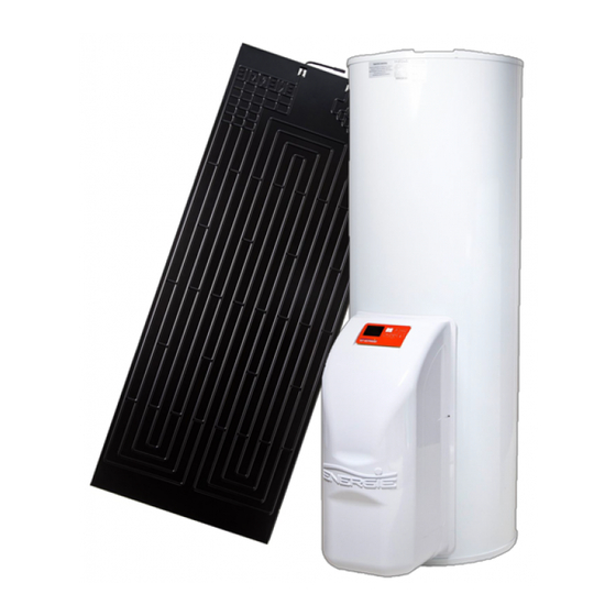
Page 12: Thermodynamic Solar Panel
Technical Manual 3.4.2. Thermodynamic Solar Panel The panel has a standard dimension of 2000 mm x 800 mm x 20 mm. The solar panel is a roll-bond type plate manufactured double channel pressed The panel connections are Flare SAE (threaded) aluminium, with post-press... -
Page 13: Storage Water Heater
Technical Manual 3.4.3. Storage Water Heater The storage water heater has a cold water inlet, hot water outlet, AQS return and an outlet for the The hot storage water heater is vertical and rests expansion valve. It also comes equipped with a on the floor. - Page 14 Technical Manual Seal with features Model Production number Serial number Production date Volume Weight Downstream pressure of pressure throttle valve Upstream Maximum Pressure of pressure throttle valve Maximum pressure in Storage Water Heater Maximum Temperature in Storage Water Heater Recommended Temperature in Storage Water Heater...
- Page 15 Technical Manual Dimensions of Storage Water Heater Version 250i 89mm 830mm 1341mm 1469mm 580mm 880mm 1545mm 370mm 765mm 300i 89mm 830mm 1558mm 1686mm 580mm 880mm 1765mm 370mm 765mm 200esm 89mm 665mm 1161mm 1289mm 580mm 880mm 1365mm 370mm 765mm 250esm 89mm 830mm 1341mm 1469mm...
-
Page 16: Thermodynamic Block
Technical Manual 3.4.4. Thermodynamic Block to the storage water heater through three M8 bolts. We call Thermodynamic Block to the equipment The thermodynamic block is also connected to the set on a galvanized steel structure, that contains condenser / coil that surrounds the storage water two of the main elements for running the thermodynamic cycle: compressor and expansion heater through two “One-Shot”... -
Page 17: Cooling Fluid
Technical Manual 3.4.5. Cooling Fluid 3.5.4. Protection against corrosion The storage water heater in this equipment can The R134a is a HFC coolant, thus not harmful to be of two types: Stainless steel or Enamelled. the ozone layer. It has great chemical and thermal stability, low toxicity, non-inflammable, and is Besides being resistant to corrosion, the storage compatible with most materials. -
Page 18: Expansion Vessel
Technical Manual So the installer must tighten the joints (C) in the water inlet and outlet (A and B), before attaching the piping (D), as demonstrated in the following sequence: 3.5.6. Expansion Vessel The expansion vessel is a device whose purpose is to compensate for the increase in water volume due to temperature rise. -
Page 19: Pressure Reducing Valve
Technical Manual The safety valve must be opened regularly to 4. INSTALATION remove impurities and check that it is not Assembly sequence: blocked. The discharge pipe must be installed in a vertical position Solar panel Storage water heater ... - Page 20 Technical Manual Attachment of L-shaped fastenings and panel: The profile should be attached to the base (e.g. rooftile) through a plastic bushing and a self- thread M6 bolt which have been supplied. The attachment of the panel to the L-shaped fastenings is done through M6 bolts and its females and washers.
-
Page 21: Set-Up Of The Storage Water Heater
Technical Manual 4.2. Set-up of the Storage Water Heater b) Aim the metallic structure with the orifices to the three M8 bolts previously mentioned. Keep the equipment sheltered in places susceptible to ice crystals Choose the position closer to the main user points ... -
Page 22: Refrigerant Connections
Technical Manual 4.4. Refrigerant Connections The cooling fluid couplings must be done by a qualified technician, with professional certificate qualifications for this purpose. DANGER The thermodynamic unit holds a pre-load of fluid R134a. The cooling fluid couplings must be thermally insulated in order to prevent burns and to ensure an optimal system performance. -
Page 23: Connection To The Panels (X2)
Technical Manual Place the end of the tube so that it is pointing downwards, cutting the pipe at the intended point, making sure to clean off any burrs (e.g. with a reamer). Next, remove the covers from the panel connections, and with the aid of a cutting tool such as a penknife, remove 5 cm of the thermoretractable sleeve. -
Page 24: Connection Of Thermodynamic Block And Storage Water Heater
Technical Manual Thermodynamic Block, make sure the apparatus has been cleaned with nitrogen. For installations with two or more panels, it is essential that fluid homogenously distributed (panel entry). The equipment already comes installed with a liquid distributor so that this process can be accurately put into effect. -
Page 25: Connection Of Thermodynamic Block And Thermodynamic Panel
Technical Manual c) Tighten with a suitable wrench, applying a torque in conformity with the diameter of the pipe employed (according to table in point 4.4.1. Insufficient torque will cause leaks of cooling fluid. Excessive torque on the coupling will damage the edge of the pipe and cause leaks. -
Page 26: Load Of Nitrogen
Technical Manual Shut Valves A – 2-Way Valve B – 3-Way Valve Create a vacuum with the vacuum pump plugged to the inlet of the 3-way pressure valve as depicted, keeping the valves completely shut until there is a vacuum of 50 Pa (0.5mbar). -
Page 27: Load Of Complementary Cooling Fluid
Technical Manual 4.4.7. Load of Complementary Cooling Fluid 4.4.8. Checking good running condition To check whether your equipment is running The warranty does not apply to correctly, start it and wait at least 20-30 minutes distances longer than what has and then check these conditions: been established for the pre-load (12m) -
Page 28: Electric Connections
Technical Manual b) It is necessary to install a safety device at 4.6. Electric Connections the cold water inlet of the appliance. The To establish the electric connection of the safety device must be in compliance with equipment, check these conditions: the standard EN 1487:2002, maximum a) The thermodynamic equipment must be pressure 7 bar (0.7 MPa) - Page 29 Technical Manual Electric diagram (1 panel): Legend: Q1 – Differential D1 – Circuit-breaker LP – Low pressure gauge S1 – Temperature probe Comp – Compressor R1 – Resistance TB – Safety thermostat...
- Page 30 Technical Manual Electric diagram (2 panels): Legend: Q1 – Differential D1 – Circuit-breaker LP – Low pressure gauge S1 – Temperature probe Comp – Compressor R1 – Resistance RL – Relay TB – Safety thermostat...
-
Page 31: First Use
Technical Manual 5. FIRST USE 5.1. Filling the tank a) Open hot water tap(s). b) Open tap/cold water section valve next to safety device (this procedure also serves the purpose of checking whether the discharge valve is shut off). c) Once there is a flow from the hot water System is shut off (OFF) Press key ON/OFF tap(s), shut it. -
Page 32: System Operation
Technical Manual To reinitiate the appliance, switch it off and switch on again using the key ON/OFF. 6. SYSTEM OPERATION 6.1. Control Panel The control panel of the Thermodynamic Solar system Eco is simple and intuitive. It enables the configuration of several operating parameters according to the operating mode selected by the user. It comprises six command keys (ON / OFF / CANCEL, MENU, COMP ▲, E-HEATER ▼, DISINFECT and OK / LOCK) that enable checking the running of the equipment, consult and change parameters. -
Page 33: Description
Technical Manual 6.3. Description Time Date Operating Mode Left to right, respectively: Timer Operating Order Disinfect ON/ OK/ OFF Holidays Signalling an error Error Alarm Compressor is active Temperature Status of keyboard Electric Heater scale is active Reason for activating resistance. -
Page 34: Operating Modes
Technical Manual 6.5. Operating Modes In order to change the operating mode you do not need to Eco is programmed to work in 3 running modes, reinitiate the equipment ECO, AUTO and BOOST, which are summarized in this table: 6.5.1. ECO Operating Mode Symbols Mod. -
Page 35: Extra Functions
Technical Manual This mode enables the user to obtain hot water in 6.6.2. HOLIDAYS Function less time. To activate the Holidays function you need to access the menu and set the number of days on The user can change the operating holiday that you wish, and your equipment will mode when he wishes, he need automatically enter Standby mode until the last... -
Page 36: System Menu
Technical Manual The K1 contact can be used to take advantage of When the contact K1 closes, it activate the PV tariff with variable price. To do that, just connect Function and all the heat sources (heat pump a timer to the 5V/P2 contacts instead of a and electric heater) will be adjusted to the inverter. -
Page 37: Parameters Description
Technical Manual 8. PARAMETERS DESCRIPTION Values Code Type Description Default Português English Français Language English Deutsch Italiano Espanol Clock Date and Time Eco mode Mode Boost mode Automatic mode Holidays Number of days 0 – Disinfect function inactive Disinfect 1 – Disinfect function active once a week (weekly) 2 –... -
Page 38: Table Of Errors
Technical Manual 9. TABLE OF ERRORS The installation, assembly and repair of Eco can only be carried out by qualified technicians. Symbols Description Problem / Checking Damaged probe – Measure internal resistance of probe which is approximately 10 KΩ at the Er01 –... -
Page 39: Resolution Of Problems
Technical Manual 11. RESOLUTION OF PROBLEMS PROBLEM POSSIBLE CAUSES HOW TO PROCEED Check the power supply Power supply failure Failure in Check the corresponding circuit breaker electronic Check the integrity of the electronic board’s board Cable damaged or disconnected electric circuit Equipment is switched off Press the key ON/OFF. - Page 40 Technical Manual Outside air temperature is very The running of the equipment depends on Slow running of weather conditions Thermodynamic Inlet water temperature is very The running of the equipment depends on Solar System the inlet water temperature and excessive Low value for Set-point Increase the value of Set-point running of...
-
Page 41: System Maintenance
Technical Manual 12. SYSTEM MAINTENANANCE Seek advice with your installer about how you should proceed Before undertaking to control the anode’s condition. maintenance operation on the equipment, make sure it is not plugged to the power supply! DANGER To check the condition of your anode follow these steps: 12.1. -
Page 42: Empty The Storage Water Heater
Technical Manual Remove the hood, unscrewing the four bolts Remove the lid (1) Press key (2) to reactivate the thermostat Replace the lid (1) and then the hood, then screwing the four bolts. 12.5. Empty the Storage Water Heater Remember that the water in the storage water heater is at high temperature, so there is an... - Page 43 Technical Manual Notes _____________________________________________________________ _____________________________________________________________ _____________________________________________________________ _____________________________________________________________ _____________________________________________________________ _____________________________________________________________ _____________________________________________________________ _____________________________________________________________ _____________________________________________________________ _____________________________________________________________ _____________________________________________________________ _____________________________________________________________ _____________________________________________________________ _____________________________________________________________ _____________________________________________________________ _____________________________________________________________ _____________________________________________________________ _____________________________________________________________ _____________________________________________________________ _____________________________________________________________ _____________________________________________________________ _____________________________________________________________ _____________________________________________________________ _____________________________________________________________ _____________________________________________________________ _____________________________________________________________ _____________________________________________________________ _____________________________________________________________ ____________________________________________________________...
- Page 44 Technical Manual Warranty This warranty covers all defects to the confirmed materials, excluding the payment of any type of personal damage indemnity caused directly or indirectly by the materials. The periods indicated below start from the purchase date of the apparatus, 6 months at the latest from the leaving date from our storage warehouses.
- Page 45 Technical Manual Zona Industrial de Laúndos, Lote 48 Energie - Energia Solar Termodinâmica, LDA 4570-311 Laúndos – Póvoa de Varzim – Portugal Tel: (+351) 252 600 230 Fax: (+351) 252 600 239 Email: geral@energie.pt Web: www.energie.pt...
Need help?
Do you have a question about the ECO 200esm and is the answer not in the manual?
Questions and answers