
Related Manuals for Atmel SAMA5D3 Xplained


Summary of Contents for Atmel SAMA5D3 Xplained
- Page 1 ARM MPU Application Group SAMA5D3_XPlained Test Software Usage Guide Revision Table: Revision Date Comments 2014-01-18 draft 2014-01-24 Rev 1.0 1/15pages...
-
Page 2: Table Of Contents
ARM MPU Application Group Table of Contents Requirements ............................3 Hardware Requirements .........................3 SDcard preparation .........................4 Jumpers setting ..........................4 Test procedure ............................6 Test without LCD ..........................6 2.1.1 Connect the board as below: ..................... -
Page 3: Requirements
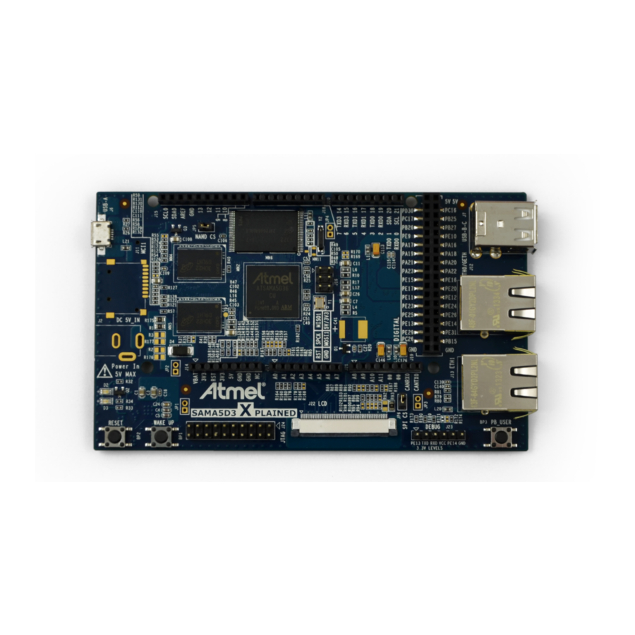
ARM MPU Application Group 1 Requirements 1.1 Hardware Requirements 1. 1 x SAMA5D3_Xplained board 2. 1 x Ethernet cable 3. 1 x uAB USB cable 4. 1 x SD card 5. 1 x optional LCD module TM4300 (PDA) with flat cable Note: A console PC connected to the DBGU port. -
Page 4: Sdcard Preparation
ARM MPU Application Group 1.2 SDcard preparation Simply dump the contents of the SDcard_IMAGE directory at the root of a standard SDcard (total 91.7MB) 1.3 Jumpers setting Set JP5 ON 4/15pages... - Page 5 ARM MPU Application Group 5/15pages...
-
Page 6: Test Procedure
ARM MPU Application Group 2 Test procedure 2.1 Test without LCD 2.1.1 Connect the board as below: Connect the both Ethernet port together (J12-J13) Insert the SD card on MCI0 J10 Connect the USB cable from PC to USB-A J6 2.1.2 HW test software AT91 Bootstrap starts and launches “prod.bin”... - Page 7 ARM MPU Application Group DBGU output view (if connected to terminal) The led red is on during the init, then off. The led blue remains on. After each test item, the led blue flashes quickly if the test result is OK ...
-
Page 8: At The End Of All Hw Test
ARM MPU Application Group 2.1.3 At the end of all HW test Case test OK : the led blue flashes 10 times, then 1 time the led red and launch a reset board to reboot DBGU output view (if connected to terminal) ... -
Page 9: Program Nand Flash With Demo
ARM MPU Application Group 2.1.4 Program nand flash with demo After HW test and result OK, the bootstrap starts erasing the nand flash and programming. The blue led is on. Program nand flash: 1mn20sec DBGU output view (if connected to terminal) Blue and Red ON: An error occurs during nand flash programming,... -
Page 10: At The End Of The Nand Flash Programming
ARM MPU Application Group 2.1.5 At the end of the nand flash programming launching Linux , T : 2mn15 to 2mn30 Test and program OK = Led Blue blink. If an error occurs during programming, simply disconnect the power and reconnect to restart the procedure. -
Page 11: Test With Lcd
ARM MPU Application Group 2.2 Test with LCD The procedure is the same as previously described. 2.2.1 Connect the board as below: Connect the flat cable to LCD connector J22 Connect the both Ethernet port together (J12-J13) Insert the SD card on MCI0 J10 ... -
Page 12: Connecting Lcd
ARM MPU Application Group 2.2.2 Connecting LCD SAMA5D3-XPlained side Lcd module side 12/15pages... -
Page 13: Launch The Test Procedure
ARM MPU Application Group 2.2.3 Launch the test procedure Press the Reset button (BP2) The Led Blue is ON, then Led Red ON and Blue OFF. Message is displayed on screen. If the message on screen is locked a long time, press the RESET button. At the end of the initialization, press one touch K1 to K4 on LCD board, or wait 5sec. -
Page 14: Test Result
ARM MPU Application Group 2.2.5 Test result At the end of the test, result message is displayed on the last line of the screen. 2.2.5.1 TEST OK Displayed: “-I- TEST OK : HW board validated” Led BLUE blink 2.2.5.2 TEST NOK Displayed: “-E- FAILED : ReSeT board to test again”... -
Page 15: Details With Console (Dbgu Output To Terminal)
ARM MPU Application Group 2.3 Details with console (DBGU output to terminal) If necessary, a console can be used to check in detail the testing procedures. Connect a USB/SERIAL cable from DEBUG port (J23) to the PC. Open terminal or equivalent (115200, n,8,1) 3 Pack EK board Follow below steps to pack EK board: Disconnect... - Page 16 Comments: Creation Date: 1/24/2014 10:58:00 AM Change Number: Last Saved On: 2/12/2014 6:09:00 PM Last Saved By: Atmel Total Editing Time: 155 Minutes Last Printed On: 2/12/2014 6:11:00 PM As of Last Complete Printing Number of Pages: 15 Number of Words: 741 (approx.) Number of Characters: 4 224 (approx.)
Need help?
Do you have a question about the SAMA5D3 Xplained and is the answer not in the manual?
Questions and answers