Table of Contents
Advertisement
SMART ARM-based Microcontrollers
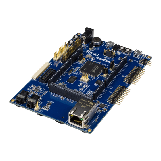
SAM V71 Xplained Ultra
USER GUIDE
Preface
®
The Atmel
| SMART SAM V71 Xplained Ultra evaluation kit is a hardware
®
®
platform to evaluate the ATSAMV71Q21, and other Atmel ARM
Cortex
-
M7-based microcontrollers in the SAM V70, SAM S70, and SAM E70 series.
Supported by the Atmel Studio integrated development platform, the kit
provides easy access to the features of the Atmel ATSAMV71Q21 and
explains how to integrate the device in a custom design.
The Xplained Ultra series evaluation kits include an on-board Embedded
Debugger, and no external tools are necessary to program or debug the
ATSAMV71Q21.
The Xplained Pro extension kits offers additional peripherals to extend the
features of the board and ease the development of custom designs.
Atmel-42408C-SAM-V71-Xplained-Ultra_User Guide-09/2015
Advertisement
Table of Contents

Related Manuals for Atmel SAM V71 Xplained Ultra


Summary of Contents for Atmel SAM V71 Xplained Ultra
-
Page 1: Preface
SAM V71 Xplained Ultra USER GUIDE Preface ® The Atmel | SMART SAM V71 Xplained Ultra evaluation kit is a hardware ® ® platform to evaluate the ATSAMV71Q21, and other Atmel ARM Cortex M7-based microcontrollers in the SAM V70, SAM S70, and SAM E70 series. -
Page 2: Table Of Contents
4.3.3. LEDs..........................29 4.3.4. SDRAM........................29 4.3.5. QSPI Flash........................30 4.3.6. SD Card........................31 4.3.7. Ethernet........................31 4.3.8. AT24MAC402.......................32 4.3.9. CAN..........................33 4.3.10. Audio and External PLL....................33 4.3.11. Crypto Footprint......................34 Atmel SAM V71 Xplained Ultra [USER GUIDE] Atmel-42408C-SAM-V71-Xplained-Ultra_User Guide-09/2015... - Page 3 6.6.5. Target USB........................47 6.6.6. Ethernet RJ-45 Connector................... 47 6.6.7. Zero Ohm Resistors.....................47 7. Appendix........................50 7.1. Getting Started with IAR......................50 8. Document Revision History..................53 9. Evaluation Board/kit Important Notice..............54 Atmel SAM V71 Xplained Ultra [USER GUIDE] Atmel-42408C-SAM-V71-Xplained-Ultra_User Guide-09/2015...
-
Page 4: Introduction
Symbolic debug of complex data types including scope information – Programming and debugging – Data Gateway Interface: SPI, I C, four GPIOs – Virtual COM port (CDC) • External power input (5-14V) • USB powered Atmel SAM V71 Xplained Ultra [USER GUIDE] Atmel-42408C-SAM-V71-Xplained-Ultra_User Guide-09/2015... -
Page 5: Kit Overview
1.2. Kit Overview The Atmel SAM V71 Xplained Ultra evaluation kit is a hardware platform to evaluate the Atmel ATSAMV71Q21. The kit offers a set of features that enables the ATSAMV71Q21 user to get started with the SAM V70 and SAM V71 peripherals right away and to get an understanding of how to integrate the device in their own design. -
Page 6: Getting Started
, Windows 7, and Windows 8. Once the kit is powered the green power LED will be lit and Atmel Studio will auto detect the kit and which Xplained Pro extension board(s) are connected. Atmel Studio will present relevant information like datasheets and kit documentation. -
Page 7: Xplained Pro
Atmel Data Visualizer is used to send and receive data through DGI. The EDBG controls two LEDs on SAM V71 Xplained Ultra; a power LED and a status LED. Table 3-1 EDBG LED Control on page 7 shows how the LEDs are controlled in different operation modes. -
Page 8: Hardware Identification System
When an Xplained Pro extension is connected to an Xplained Pro MCU board the information is read and sent to Atmel Studio. The Atmel Kits extension, installed with Atmel Studio, will give relevant information, code examples, and links to relevant documents. -
Page 9: Xplained Pro Headers And Connectors
Pulse width modulation, alternatively negative part of differential IRQ/GPIO Interrupt request line and/or general purpose I/O SPI_SS_B/ Slave select for SPI and/or general purpose I/O GPIO C_SDA Data line for I C interface. Always implemented, bus type. Atmel SAM V71 Xplained Ultra [USER GUIDE] Atmel-42408C-SAM-V71-Xplained-Ultra_User Guide-09/2015... -
Page 10: Xplained Pro Lcd Extension Connector
Communication line to the ID chip on an extension board Ground Data line Data line Data line Data line Ground Data line Data line Data line Data line Ground Data line Data line Atmel SAM V71 Xplained Ultra [USER GUIDE] Atmel-42408C-SAM-V71-Xplained-Ultra_User Guide-09/2015... - Page 11 Master in slave out of serial peripheral interface SPI SS Slave select for serial peripheral interface. Preferably a dedicated pin. ENABLE Display enable C SDA C data C SCL C clock Atmel SAM V71 Xplained Ultra [USER GUIDE] Atmel-42408C-SAM-V71-Xplained-Ultra_User Guide-09/2015...
-
Page 12: Xplained Pro Power Header
Xplained Pro Power Header The power header can be used to connect external power to the SAM V71 Xplained Ultra kit. The kit will automatically detect and switch to any external power if supplied. The power header can also be used as supply for external peripherals or extension boards. -
Page 13: Hardware Users Guide
Hardware Users Guide 4.1. Power Distribution SAM V71 Xplained Ultra has four power sources as described in Power Sources on page 8. Figure 4-1 Power Supply Block Diagram on page 13 shows a block diagram of the power supply circuitry, the related I/O pins are described in Table 4-1 Power Distribution Signals... -
Page 14: Connectors
Figure 4-2 SAM V71 Xplained Ultra Connector Overview on page 15 shows all available connectors and jumpers on SAM V71 Xplained Ultra. Atmel SAM V71 Xplained Ultra [USER GUIDE] Atmel-42408C-SAM-V71-Xplained-Ultra_User Guide-09/2015... - Page 15 Figure 4-2 SAM V71 Xplained Ultra Connector Overview Atmel SAM V71 Xplained Ultra [USER GUIDE] Atmel-42408C-SAM-V71-Xplained-Ultra_User Guide-09/2015...
-
Page 16: Extension Headers
4.2.1. Extension Headers The Xplained Pro headers EXT1 and EXT2 on SAM V71 Xplained Ultra offers access to the I/O of the microcontroller in order to expand the board e.g. by connecting extensions to the board. The headers have a pitch of 2.54mm. -
Page 17: Lcd Extension Connector
25 [D18] 26 [D19] 27 [GND] 28 [D20] 29 [D21] 30 [D22] 31 [D23] 32 [GND] 33 [PCLK / CMD_DAT A_SEL] PC30 GPIO EXT1 34 [VSYNC / CS] PD19 NCS3 Shield Atmel SAM V71 Xplained Ultra [USER GUIDE] Atmel-42408C-SAM-V71-Xplained-Ultra_User Guide-09/2015... -
Page 18: Arduino Connectors
Arduino Due. Caution: Like the Arduino Due, SAM V71 Xplained Ultra runs at 3.3V and the maximum voltage that the I/O pins can tolerate is 3.3V, providing higher voltages like 5V to an I/O pin could damage the board. - Page 19 Shield, and EDBG GPIO PD30 UTXD3 Camera, EXT2, and Shield PA00 PWMC0_PWMH0 EXT1 PA06 GPIO Camera, MediaLB, and EXT2 PD27 PWMC0_PWML3 Camera, EXT2, and Shield PD11 PWMC0_PWMH0 Audio, Camera, and EXT2 Atmel SAM V71 Xplained Ultra [USER GUIDE] Atmel-42408C-SAM-V71-Xplained-Ultra_User Guide-09/2015...
- Page 20 PD20 MISO SPI0_MISO EXT1, EXT2, Shield, and EDBG SPI VCC_P5V0 - PD22 SCLK SPI0_SPCK Camera, EXT1, EXT2, Shield, EDBG SPI PD21 MOSI SPI0_MOSI PLL, Camera, EXT1, EXT2, Shield, and EDBG SPI Atmel SAM V71 Xplained Ultra [USER GUIDE] Atmel-42408C-SAM-V71-Xplained-Ultra_User Guide-09/2015...
- Page 21 Arduino pin Function Shared functionality name number VCC_P5V0 - VCC_P5V0 - PA18 PCK2 Audio PB01 Audio, EXT1, and Shield PB00 Audio, EXT1, and Shield PD19 CTS2 Shield PD18 RTS2 SD Card Shield Atmel SAM V71 Xplained Ultra [USER GUIDE] Atmel-42408C-SAM-V71-Xplained-Ultra_User Guide-09/2015...
-
Page 22: Medialb Connector
MOST (Media Oriented Systems Transport) Network data, or to communicate with other applications, with minimum effort. On SAM V71 Xplained Ultra the MLB module of the ATSAMV71Q21 is connected to a MediaLB connector implemented with a 40 pin SAMTEC QSH-020-01-L-D-DP-A. - Page 23 LCD, EXT2, Shield, and EDBG GPIO3 17 [RESERVED] 18 [SR0] 19 [RESERVED] 20 [RESERVED] 21 [PS0] 22 [PS1] 23 [STATUS] 24 [PWROFF] 25 [RESET_N] PA06 GPIO Camera, EXT2, and Shield 26 [RSOUT] Atmel SAM V71 Xplained Ultra [USER GUIDE] Atmel-42408C-SAM-V71-Xplained-Ultra_User Guide-09/2015...
-
Page 24: Camera Connector
3 [VCC] VCC_TARGET_P3V3 4 [GND] 5 [RESET] PB13 GPIO Shield 6 [PWD] PC19 ISI_PWD EXT2 Shield 7 [I2C_SCK] PA04 TWCK0 EXT1, EXT2, EDBG I LCD, Audio, PLL, MediaLB, EEPROM, Crypto, and Shield Atmel SAM V71 Xplained Ultra [USER GUIDE] Atmel-42408C-SAM-V71-Xplained-Ultra_User Guide-09/2015... -
Page 25: Usb
4.2.6. The SAM V71 Xplained Ultra has a Micro-USB connector for use with the SAM V71 USB module labeled as TARGET USB on the kit. In USB host mode VBUS voltage is provided by the kit and has to be enabled by setting the "VBUS Host Enable"... -
Page 26: Super Capacitor
4.2.9. VDDCORE Current Measurement A 1x2, 100mil pin-header marked with J201 is located at the center of the SAM V71 Xplained Ultra. All power to VCCDORE of the ATSAMV71Q21 is routed through this header. To measure the power consumption of VDDCORE remove the jumper and replace it with an ampere meter. -
Page 27: Chip Erase Header
4.2.11. Trace Connector ATSAMV71Q21 supports 4-bit parallel trace. SAM V71 Xplained Ultra implements a CoreSight 20 20-pin, 50-mil keyed connector (pin seven is removed). -
Page 28: Peripherals
4.3.1. Crystals The SAM V71 Xplained Ultra kit contains two crystals that can be used as clock sources for the SAM V71 device. The crystals have cut-straps next to them that can be used to measure the oscillator safety factor. -
Page 29: Leds
Chip Erase 4.3.3. LEDs There are two yellow LEDs available on the SAM V71 Xplained Ultra board that can be turned on and off. The LEDs can be activated by driving the connected I/O line to GND. Table 4-22 LED Connection... -
Page 30: Qspi Flash
Shield NBS1 4.3.5. QSPI Flash The SAM V71 Xplained Ultra features one external SPANSION, S25FL116K, 2MB, QSPI Flash. QSPI Slash access can be configured in the QSPI module in the SAM V71. Table 4-24 QSPI Flash Connections on page 31 lists all I/O-lines connected to the QSPI Flash. -
Page 31: Sd Card
PA11 Chip Select 4.3.6. SD Card The SAM V71 Xplained Ultra has one standard SD card connector which is connected to High Speed Multimedia Card Interface (HSMCI) of the SAM V71. Table 4-25 SD Card Connection on page 31 lists all I/O-lines connected to the SD card connector. -
Page 32: At24Mac402
Quiet-WIRE filtering enabled 4.3.8. AT24MAC402 The SAM V71 Xplained Ultra features one external AT24MAC402 serial EEPROM with a EIA-48 MAC address connected to the SAM V71 through I C. This device contain a MAC address for use with the Ethernet interface. -
Page 33: Can
4.3.10. Audio and External PLL SAM V71 Xplained Ultra includes a WOLFSON WM8904 Audio CODEC for input and output of digital sound, the kit has two 3.5mm stereo jacks for microphone input and headphone output. There is also an (optional) external PLL, Cirrus Logic CS2100CP, that can be used to generate a reference clock to the WM8904. -
Page 34: Crypto Footprint
Several of Atmels security devices, including CryptoAuthentication devices like the ATSAH204A, only requires I C to interface and they share the same packages and pinouts. SAM V71 Xplained Ultra has implemented SOIC8 and UDFN8 footprints for these devices so the user may solder them on themselves. -
Page 35: Zero Ohm Resistors
4.4. Zero Ohm Resistors SAM V71 Xplained Ultra has several zero ohm resistors that can be used to disconnect I/O pins of the ATSAMV71Q21 from connectors and on-board ICs and to disconnect power signals. All Arduino pin numbers are listed in Arduino Connectors on page 18. - Page 36 R800 Audio Headphone jack R802 Audio Headphone jack R806 Microphone jack Audio R811 Microphone jack Audio R814 Audio GND R815 Audio GND R816 Audio GND R818 PLL AD0 C address select Atmel SAM V71 Xplained Ultra [USER GUIDE] Atmel-42408C-SAM-V71-Xplained-Ultra_User Guide-09/2015...
- Page 37 Designator Mounted From Comment R819 VCC_P1V8 Audio DCVDD R920 VCC_P3V3 VCC_EDBG_P3V3 Atmel SAM V71 Xplained Ultra [USER GUIDE] Atmel-42408C-SAM-V71-Xplained-Ultra_User Guide-09/2015...
- Page 38 C815 R223 U800 C814 R801 C800 R226 R809 C806 R224 R810 C807 C821 C817 C820 R811 C816 L805 L804 R812 R813 C802 C801 C1001 C1002 C804 C803 C812 C813 L702 C1000 Atmel SAM V71 Xplained Ultra [USER GUIDE] Atmel-42408C-SAM-V71-Xplained-Ultra_User Guide-09/2015...
- Page 39 PD26 PC19 PB01 PE04 PA24 PA02 PB00 PA04 PA03 PD16 PD24 PB04 PA21 PD15 PA10 PD21 PD27 PD19 PA22 PD22 PD20 PD18 PE05 PD27 PB13 PD28 PD00 PB03 PB02 J600 TP600 Atmel SAM V71 Xplained Ultra [USER GUIDE] Atmel-42408C-SAM-V71-Xplained-Ultra_User Guide-09/2015...
-
Page 40: Embedded Debugger Implementation
ATSAMV71Q21 using Serial Wire Debug (SWD). The Embedded Debugger also include a Virtual Com port interface over UART, an Atmel Data Gateway Interface over SPI, and TWI and it includes four of the SAM V71 GPIOs. Atmel Studio can be used as a front end for the Embedded Debugger. - Page 41 Table 4-38 GPIO Lines Connected to the EDBG SAM V71 pin Function Shared functionality PA09 GPIO0 Camera PA23 GPIO1 LED0 PD28 GPIO2 EXT1, Camera, LCD, and Shield PA02 GPIO3 EXT2, LCD, and Shield Atmel SAM V71 Xplained Ultra [USER GUIDE] Atmel-42408C-SAM-V71-Xplained-Ultra_User Guide-09/2015...
-
Page 42: Kit Specific Data
Kit Specific Data One of the flash user pages in the EDBG is programmed with data specific to SAM V71 Xplained Ultra. The data can be read through the I C interface connected to the EDBG from the target application. For... -
Page 43: Hardware Revision History And Known Issues
6.1. Identifying Product ID and Revision The revision and product identifier of Xplained Pro boards can be found in two ways; either through Atmel Studio or by looking at the sticker on the bottom side of the PCB. By connecting an Xplained Pro MCU board to a computer with Atmel Studio running, an information window will pop up. -
Page 44: 12Mhz Crystal Selection
6.5.1. PCB Revision Marking One thousand SAM V71 Xplained Ultra revision 8 kits have revision 3 PCBs (A08-2216) that are marked with "Revision 2" under the location of the serial number sticker. These PCBs can be identified by the addition of the "USB VBUS" and "SUPER CAP" connectors shown Figure 4-2 ... -
Page 45: Revision 6
IRQ1 (EXT4), and Xplained Pro extension header 1 IRQ (EXT1). If a camera with 10-bit mode is used together with a display connected to EXT4 the display IRQ line will conflict with the camera. On revision 6 of SAM V71 Xplained Ultra pin 41 (DISPLAY ENABLE) on the LCD connector is not connected to anything (floating). - Page 46 Figure 6-2 SAM V71 Xplained Ultra Connector Overview Atmel SAM V71 Xplained Ultra [USER GUIDE] Atmel-42408C-SAM-V71-Xplained-Ultra_User Guide-09/2015...
-
Page 47: Target Usb
PCB. 6.6.6. Ethernet RJ-45 Connector On revision 6 of SAM V71 Xplained Ultra the TX and RX differential pairs has a swapped position on the RJ-45 connector compared to what is normal. Table 6-1 Ethernet RJ-45 Connector Pin-out Component pin... - Page 48 C815 R223 U800 C814 R801 C800 R226 R809 C806 R224 R810 C807 C821 C817 C820 R811 C816 L805 L804 R812 R813 C802 C801 C1001 C1002 C804 C803 C812 C813 L702 C1000 Atmel SAM V71 Xplained Ultra [USER GUIDE] Atmel-42408C-SAM-V71-Xplained-Ultra_User Guide-09/2015...
- Page 49 PD26 PC19 PB01 PE04 PA24 PA02 PB00 PA04 PA03 PD16 PD24 PB04 PA21 PD15 PA10 PD21 PD27 PD19 PA22 PD22 PD20 PD18 PE05 PD27 PB13 PD28 PD00 PB03 PB02 J600 TP600 Atmel SAM V71 Xplained Ultra [USER GUIDE] Atmel-42408C-SAM-V71-Xplained-Ultra_User Guide-09/2015...
-
Page 50: Appendix
Select System (default) as the reset method. In the category Debugger > CMSIS DAP, select the JTAG/SWD tab. Select SWD as the interface and optionally select the SWD speed. Figure 7-1 Select Target Device Atmel SAM V71 Xplained Ultra [USER GUIDE] Atmel-42408C-SAM-V71-Xplained-Ultra_User Guide-09/2015... - Page 51 Figure 7-2 Select Debugger Figure 7-3 Configure Flash Loader Atmel SAM V71 Xplained Ultra [USER GUIDE] Atmel-42408C-SAM-V71-Xplained-Ultra_User Guide-09/2015...
- Page 52 Figure 7-4 Configure Reset Figure 7-5 Configure Interface Atmel SAM V71 Xplained Ultra [USER GUIDE] Atmel-42408C-SAM-V71-Xplained-Ultra_User Guide-09/2015...
-
Page 53: Document Revision History
ERRATA, and added IAR getting started guide. 42408B 06/2015 Updated user guide to reflect revision 8 of the kit, see Revision 6 on page 45 for ERRATA. 42408A 02/2015 Initial document release. Atmel SAM V71 Xplained Ultra [USER GUIDE] Atmel-42408C-SAM-V71-Xplained-Ultra_User Guide-09/2015... -
Page 54: Evaluation Board/Kit Important Notice
(WEEE), FCC, CE or UL (except as may be otherwise noted on the board/kit). Atmel supplied this board/kit "AS IS," without any warranties, with all faults, at the buyer's and further users' sole risk. The user assumes all responsibility and liability for proper and safe handling of the goods. - Page 55 DISCLAIMER: The information in this document is provided in connection with Atmel products. No license, express or implied, by estoppel or otherwise, to any intellectual property right is granted by this document or in connection with the sale of Atmel products. EXCEPT AS SET FORTH IN THE ATMEL TERMS AND...
- Page 56 Mouser Electronics Authorized Distributor Click to View Pricing, Inventory, Delivery & Lifecycle Information: Atmel ATSAMV71-XULT...
Need help?
Do you have a question about the SAM V71 Xplained Ultra and is the answer not in the manual?
Questions and answers