Table of Contents
Advertisement
SMART
Atmel | SMART SAMA5D2 Series
Introduction
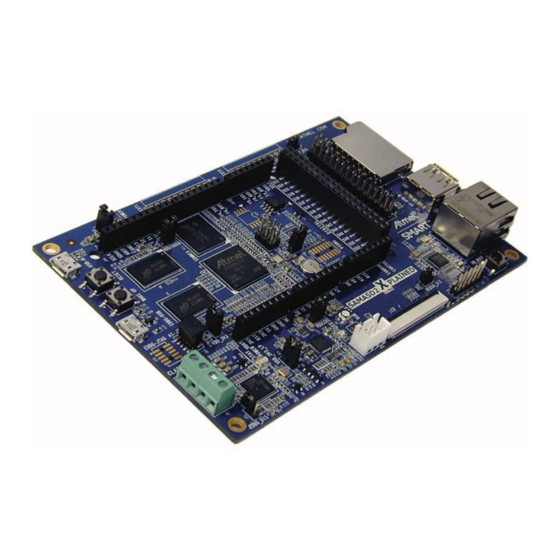
This user guide introduces the Atmel
(SAMA5D2-XULT) and describes the development and debugging capabilities for
applications running on the Atmel | SMART SAMA5D2 ARM
embedded microprocessor unit (eMPU).
Scope
This guide provides details on the SAMA5D2-XULT. It is made up of five main
sections:
Section 1.
describes the evaluation kit content and its main features.
Section 2.
provides instructions to power up the SAMA5D2-XULT board.
Section 3.
provides information on obtaining sample code and technical
support.
Section 4.
provides an overview of the SAMA5D2-XULT board.
Section 5.
describes the SAMA5D2-XULT board components.
SAMA5D2 Xplained Ultra Evaluation Kit
®
SAMA5D2 Xplained Ultra evaluation kit
Atmel-44028B-ATARM-SAMA5D2-Xplained-Ultra-User Guide_02-Oct-15
USER GUIDE
®
®
Cortex
-A5-based
Advertisement
Table of Contents

Related Manuals for Atmel SAMA5D2-XULT


Summary of Contents for Atmel SAMA5D2-XULT
-
Page 1: Introduction
Atmel | SMART SAMA5D2 ARM Cortex -A5-based embedded microprocessor unit (eMPU). Scope This guide provides details on the SAMA5D2-XULT. It is made up of five main sections: Section 1. describes the evaluation kit content and its main features. -
Page 2: Kit Contents
Kit Contents The SAMA5D2-XULT includes: Board ̶ One SAMA5D2-XULT board Cables ̶ One Micro-AB type USB cable Welcome letter SAMA5D2 Xplained Ultra [USER GUIDE] Atmel-44028B-ATARM-SAMA5D2-Xplained-Ultra-User Guide_02-Oct-15... -
Page 3: Table Of Contents
SAMA5D2-XULT Board Schematics ........ -
Page 4: Evaluation Kit Specifications
Evaluation Kit Specifications Table 1-1. Evaluation Kit Specifications Characteristic Specifications Board SAMA5D2-XULT Board supply voltage USB and/or Battery powered Operating 0°C to +70°C Temperature Storage -40°C to +85°C Relative Humidity 0 to 90% (non-condensing) Dimensions: Main board 135 × 88 × 20 mm... -
Page 5: Power Source
Powered through a rechargeable battery Li-polymer 3.7V connected to J3 or J4 Powered through the USB Micro-AB connector on the Atmel Embedded Debugger (EDBG) interface (J14) Unlike Arduino Uno boards, the SAMA5D2-XULT board runs at 3.3V. The maximum WARNING voltage that the I/O pins can tolerate is 3.3V. -
Page 6: Sample Code And Technical Support
Sample Code and Technical Support After boot up, you can run some sample code or your own application on the development kit. You can download sample code and get technical support from www.atmel.com. Linux software and demos can be found on http://www.at91.com/linux4sam/bin/view/Linux4SAM/. -
Page 7: Hardware Overview
Equipment List The SAMA5D2-XULT board is based on the integration of an ARM Cortex-A5-based microprocessor with external memory, one Ethernet physical layer transceiver, one SD/MMC interface, one host USB port and one device USB port, one 24-bit RGB LCD and debug interfaces. -
Page 8: Board Components
Board Components Board Overview The fully-featured SAMA5D2-XULT board integrates multiple peripherals and interface connectors as shown in Figure 5-1. Figure 5-1. SAMA5D2-XULT Board Overview WWW.ATMEL.COM BOOT_DIS R184 R183 R176 R174 R172 R170 R168 R166 R177 R175 VDDIODDR R173 R171 R169... -
Page 9: Connectors On Board
Connectors on board Table 5-2 describes the interface connectors on the SAMA5D2-XULT. Table 5-2. SAMA5D2-XULT Board Interface Connectors Connector Interfaces to USB A Device. Supports USB device using a type Micro-AB connector USB Host B. Supports USB host using a type A connector Serial DBGU (3.3V level) - Page 10 The ACT8945A features three step-down DC-DC converters and four low-noise, low-dropout linear regulators along with a complete battery charging solution featuring the advanced ActivePath™ system-power selection function. WARNING Refer to the ACT8945A datasheet at www.active-semi.com for more details. SAMA5D2 Xplained Ultra [USER GUIDE] Atmel-44028B-ATARM-SAMA5D2-Xplained-Ultra-User Guide_02-Oct-15...
- Page 11 ̶ 3.3V VDDIOP, VDDISC, VDDEDBG ̶ 2.5V VDDFUSE ̶ 3.3V VDDOSC, VDDUTMI, VDDANA, VDDAUDIOPLL Power supplies to external chips on the main board: ̶ 1.8V VDDSDHC1V8 ̶ 2.5V VDDLED ̶ 4.8V VSYS_5V SAMA5D2 Xplained Ultra [USER GUIDE] Atmel-44028B-ATARM-SAMA5D2-Xplained-Ultra-User Guide_02-Oct-15...
- Page 12 5.3.2.5 Input Power Options There are several power options for the SAMA5D2-XULT board. The USB-powered operation is the default configuration. It comes from the USB device port connected to a PC or a 5V DC supply. The USB supply is sufficient to power the board in most applications. It is important to note that when the USB supply is used, the USB-B Host port has limited power.
- Page 13 Open-Drain Interrupt Output. nIRQ is asserted any time an unmasked fault condition exists or a charger PB13 interrupt occurs. nLBO: Low Battery Indicator Output. nLBO is asserted low whenever the voltage at LBI is lower than1.2V; it is high- Z otherwise. SAMA5D2 Xplained Ultra [USER GUIDE] Atmel-44028B-ATARM-SAMA5D2-Xplained-Ultra-User Guide_02-Oct-15...
- Page 14 5.3.2.7 Backup Power Supply The SAMA5D2-XULT board requires a power source in order to permanently power the backup part of the SAMA5D2 device (refer to SAMA5D2 Series datasheet). A super capacitor sustains such permanent power to VDDBU when all system power sources are off.
- Page 15 Reset push button: When pressed, the ACT8945A transfers the reset signal to the MPU. 5.3.3 Reset Circuitry The reset sources for SAMA5D2-XULT board are: Power-on reset from the power management unit (PMIC) Push button reset BP3 ...
- Page 16 The SAMA5D2 features a DDR/SDR memory interface and an External Bus Interface (EBI) to permit interfacing to a wide range of external memories and to almost any kind of parallel peripheral. This section describes the memory devices that equip the SAMA5D2-XULT board. 5.3.5.2...
- Page 17 DDR_DQM3 23.2K 1% 22pF DDR_DQS0+ DDR_DQS0 DDR_DQS0- R250 C106 DDR_DQSN0 R242 DDR_DQS1+ 100K DDR_DQS1 DDR_DQS1- DDR_DQSN1 DDR_DQS2+ DDR_DQS2 DDR_RESETN DDR_DQS2- DDR_RESETN DDR_DQSN2 DDR_VREF DDR_DQS3+ DDR_VREFB0 DDR_DQS3 DDR_DQS3- DDR_VREFCM DDR_DQSN3 C100 100nF 100nF SAMA5D27-CN SAMA5D2 Xplained Ultra [USER GUIDE] Atmel-44028B-ATARM-SAMA5D2-Xplained-Ultra-User Guide_02-Oct-15...
- Page 18 NC45 NC90 NC46 100nF NC89 NC47 NC88 NC48 NC87 NC49 NC86 NC50 NC85 NC51 NC84 NC52 R211 NC83 NC53 NC82 NC54 SDHC0_VDDSEL_PA11 IN=0: S1 Closed IN=1: S2 Closed R225 U11 MTFC4GLDEA-0M WT ADG849 SAMA5D2 Xplained Ultra [USER GUIDE] Atmel-44028B-ATARM-SAMA5D2-Xplained-Ultra-User Guide_02-Oct-15...
- Page 19 JP9 = OFF (default) → enable normal boot from eMMC or serial Flash if mounted JP9 = ON → booting from optional serial DataFlash or eMMC is disabled Refer to the SAMA5D2 Series datasheet for more information on standard boot strategies and sequencing. SAMA5D2 Xplained Ultra [USER GUIDE] Atmel-44028B-ATARM-SAMA5D2-Xplained-Ultra-User Guide_02-Oct-15...
- Page 20 Flash memories Figure 5-16. Optional QSPI Serial DataFlash VDD_3V3 QSPI0_IO0_PA24 100nF QSPI0_IO1_PA25 QSPI0_CS QSPI0_IO2_PA26 W#/VPP/DQ2 QSPI0_IO3_PA27 QSPI0_SCK_PA22 HOLD#/DQ3 DNP(N25Q128A13ESE40F) SAMA5D2 Xplained Ultra [USER GUIDE] Atmel-44028B-ATARM-SAMA5D2-Xplained-Ultra-User Guide_02-Oct-15...
- Page 21 The EUI-48/64 addresses can be assigned as the actual physical address of a system hardware device or node, or it can be assigned to a software instance. These addresses are factory-programmed by Atmel and guaranteed unique. They are permanently write-protected in an extended memory block located outside of the standard 2-Kbit memory array.
-
Page 22: Pio Usage And Interface Connectors
5.4.1.1 Secure Digital Multimedia Card (SDMMC) Controller The SAMA5D2-XULT board has two Secure Digital Multimedia Card (SDMMC) interfaces that support the MultiMedia Card (e.MMC) Specification V4.41, the SD Memory Card Specification V3.0, and the SDIO V3.0 specification. It is compliant with the SD Host Controller Standard V3.0 specification. - Page 23 – Common ground – Supply Voltage 3.3V PA22 Clock / Command Line PA30 Card Detect DAT0 PA18 Data Bit 0 DAT1 PA19 Data Bit 1 DAT2 PA20 Data Bit 2 – Common ground SAMA5D2 Xplained Ultra [USER GUIDE] Atmel-44028B-ATARM-SAMA5D2-Xplained-Ultra-User Guide_02-Oct-15...
- Page 24 5.4.2.1 Ethernet 10/100 (GMAC) Port The SAMA5D2-XULT board contains a MICREL PHY device (KSZ8081) operating at 10/100 Mb/s. The board supports RMII interface modes. The Ethernet interface consists of two pairs of low-voltage differential pair signals designated from GRX± and GTX± plus control signals for link activity indicators. These signals can be used to connect to a 10/100 Base-T RJ45 connector integrated on SAMA5D2-XULT board.
- Page 25 EARTH / GND Common ground ACT LED LED activity ACT LED LED activity LINK LED LED link connection LINK LED LED link connection EARTH / GND Common ground EARTH / GND Common ground – – SAMA5D2 Xplained Ultra [USER GUIDE] Atmel-44028B-ATARM-SAMA5D2-Xplained-Ultra-User Guide_02-Oct-15...
- Page 26 5.4.2.2 USB Host/Device A, B The SAMA5D2-XULT board features three USB communication ports: USB Host B High- and Full-speed Interface ̶ One USB host type A connector. USB A Device Interface ̶ One USB device standard micro-AB connector. This port has a VBUS detection function made through the resistor ladder R183 and R184.
- Page 27 R126 R146 R106 R107 R139 VDDBU R101 R102 R131 L12 R130 EDBG-JTAG A5-JTAG R104 R103 R123 R105 R100 VDD_3V3 CLASS D VDDCORE DEBUG_DIS PB_USER VBAT DEBUG EDBG_DIS RXD VCC RTS GND TP1 TP2 SAMA5D2 Xplained Ultra [USER GUIDE] Atmel-44028B-ATARM-SAMA5D2-Xplained-Ultra-User Guide_02-Oct-15...
- Page 28 LCD TFT Interface 5.4.5.1 The SAMA5D2-XULT board provides 18 bits of data and control signals to the LCD interface. Other signals are used to control the LCD and are available on connector J2: TWI, SPI, two GPIOs for interrupt, 1-Wire and power supply lines.
- Page 29 – – – – – – – – – – – LCDDAT2 PC10 Data line – LCDDAT3 PC11 Data line – – – LCDDAT4 PC12 Data line – LCDDAT5 PC13 Data line – SAMA5D2 Xplained Ultra [USER GUIDE] Atmel-44028B-ATARM-SAMA5D2-Xplained-Ultra-User Guide_02-Oct-15...
- Page 30 TWI_SDA I2C data line (maXTouch) – TWCK1 TWI_SCL I2C clock line (maXTouch) – GPIO IRQ1 maXTouch interrupt line – GPIO IRQ2 Interrupt line for other I2C devices – LCDPWM PC28 Backlight control – SAMA5D2 Xplained Ultra [USER GUIDE] Atmel-44028B-ATARM-SAMA5D2-Xplained-Ultra-User Guide_02-Oct-15...
- Page 31 LCD Connector J2 Signal Descriptions (Continued) Signal Signal RGB Interface Function Alternate RESET – RESET Reset for both display and maXTouch – Main_5V/3V3 3.3V or 5V supply (0R) – Main_5V/3V3 3.3V or 5V supply (0R) – – SAMA5D2 Xplained Ultra [USER GUIDE] Atmel-44028B-ATARM-SAMA5D2-Xplained-Ultra-User Guide_02-Oct-15...
- Page 32 PB11 Reset ISC module ISI_PWD PB12 Power Down module TWCK1 TWI Clock TWD1 TWI Data – Ground ISC_MCK ISC Master Clock – Ground ISC_VSYNC ISC Vertical Synchronization – Ground ISI_HSYNC ISC Horizontal Synchronization SAMA5D2 Xplained Ultra [USER GUIDE] Atmel-44028B-ATARM-SAMA5D2-Xplained-Ultra-User Guide_02-Oct-15...
- Page 33 D[3] D[2] D[1] D[0] Not Used isc_data[2] D[2] D[1] D[0] Not Used Not Used isc_data[1] D[1] D[0] Not Used Not Used Not Used isc_data[0] D[0] Not Used Not Used Not Used Not Used SAMA5D2 Xplained Ultra [USER GUIDE] Atmel-44028B-ATARM-SAMA5D2-Xplained-Ultra-User Guide_02-Oct-15...
- Page 34 VSYS_5V 1N4148W PMOS R311 C158 10nF CLASSD_R0_PB1 CLASSD_R1_PB2 R315 NMOS U17 DMC2400UV 180ohm at 100MHz Right P Right N 180ohm at 100MHz 1N4148W PMOS R322 C159 10nF CLASSD_R2_PB3 CLASSD_R3_PB4 R324 NMOS U19 DMC2400UV SAMA5D2 Xplained Ultra [USER GUIDE] Atmel-44028B-ATARM-SAMA5D2-Xplained-Ultra-User Guide_02-Oct-15...
- Page 35 PB_USER VBAT DEBUG EDBG_DIS RXD VCC RTS GND TP1 TP2 Table 5-12. CLASSD Output Connector J5 Signal Descriptions Mnemonic Signal Description VSYS_5V Power OUTPUT RIGHT P Positive Level OUTPUT RIGHT N Negative Level SAMA5D2 Xplained Ultra [USER GUIDE] Atmel-44028B-ATARM-SAMA5D2-Xplained-Ultra-User Guide_02-Oct-15...
- Page 36 5.4.8 Tamper Interface The SAMA5D2-XULT board features eight tamper pins for static or dynamic intrusion detections, UART reception, and two analog pins for comparison. Intrusion detection is described in the document “Security Module”, Atmel literature No. 44036. This document is available under Non-Disclosure Agreement (NDA).
- Page 37 CLASS D VDDCORE DEBUG_DIS PB_USER VBAT DEBUG EDBG_DIS RXD VCC RTS GND TP1 TP2 Table 5-13. Tamper Connector J12 Signal Descriptions Signal Pin No. Signal PIOBU0 PIOBU1 PIOBU2 PIOBU3 PIOBU4 PIOBU5 PIOBU6 PIOBU7 SAMA5D2 Xplained Ultra [USER GUIDE] Atmel-44028B-ATARM-SAMA5D2-Xplained-Ultra-User Guide_02-Oct-15...
- Page 38 5.4.10 RGB LED There is one RGB LED on the SAMA5D2-XULT board; it can be controlled by the user. The three LED cathodes are controlled via GPIO PWM pins. Figure 5-35. RGB LED Indicators 470R R326 VDD_LED LED_RED_PB6 470R R325...
- Page 39 TDI TEST DATA INPUT - Serial data output line, JTAG data input into target CPU sampled on the rising edge of the TCK signal Common ground nSRST RESET Active-low reset signal. Target CPU reset signal. SAMA5D2 Xplained Ultra [USER GUIDE] Atmel-44028B-ATARM-SAMA5D2-Xplained-Ultra-User Guide_02-Oct-15...
- Page 40 5.4.12.2 Serial Console Port The SAMA5D2-XULT board has a dedicated serial port for debugging, which is accessible through the 6-pin male header J1. Various interfaces can be used as USB/Serial DBGU port bridge, such as FTDI TTL-232R USB to TTL serial cable or basic breakout board for the RS232/USB converter.
- Page 41 The Atmel Embedded Debugger (EDBG) is an intuitive plug-and-play solution which adds full programming and debugging support to embedded hardware kits containing Atmel microcontrollers. It enables seamless integration between the target hardware and the Atmel Studio front end. In addition to the Virtual COM port which provides a UART bridge to the target device, the EDBG provides a Data Gateway Interface, through which the target device and host PC can communicate, facilitating high-level application debugging, monitoring, graphing and logging of system information in real-time.
- Page 42 The EDBG is based on the Atmel AT32UC3A4256J high-performance low-power 32-bit AVR microcontroller running at up to 60 MHz. The device includes an on-chip USB 2.0 high-speed hardware module with dedicated DMA channels, making it ideal for data communications. By default, the EDBG is in Reset state and not usable. To use the EDBG interface, remove the jumper JP1. To avoid any conflicts with the debug signals, do not use the JTAG and EDBG at the same time.
- Page 43 VDDCORE DEBUG_DIS PB_USER VBAT DEBUG EDBG_DIS RXD VCC RTS GND TP1 TP2 Table 5-16. USB Connector J14 Signal Descriptions Mnemonic Signal Description VBUS 5V power Data minus Data plus On-the-go identification Common ground SAMA5D2 Xplained Ultra [USER GUIDE] Atmel-44028B-ATARM-SAMA5D2-Xplained-Ultra-User Guide_02-Oct-15...
-
Page 44: Pio Usage On Expansion Connectors
Five 8-pin, one 6-pin, one 10-pin and one 36-pin headers (J7, J8, J9, J16, J17, J20, J21, J22) are provided on the SAMA5D2-XULT board to enable the PIO connection of various expansion cards. These headers’ physical and electrical implementation match the Arduino R3 extension (“shields”) system. - Page 45 Arduino extension headers. To enable these signals, SAMA5D27 PIO multiplexing must be properly configured. For more details, refer to Section 5.6 “SAMA5D2-XULT Board Schematics” and the section PIO Controller (PIO) in the SAMA5D2 Series datasheet.
- Page 46 I2SDO1 SDHC1_DAT0 LCDDEN NANDRDY PCK0 UTXD1 ISI_FIELD PC27 LCDDAT23 GTX3 PCK1 CANRX1 TWD0 PC26 LCDDAT22 – GTX2 CANTX1 – PC11 LCDDAT1 GTXEN ISI_D2 TCLK4 CANRX0 A0/NBS0 PC10 LCDDAT0 GTXCK ISI_D1 TIOB4 CANTX0 – SAMA5D2 Xplained Ultra [USER GUIDE] Atmel-44028B-ATARM-SAMA5D2-Xplained-Ultra-User Guide_02-Oct-15...
- Page 47 I2SDO1 SDHC1_DAT0 LCDDEN NANDRDY PCK0 UTXD1 ISI_FIELD PC27 LCDDAT23 GTX3 PCK1 CANRX1 TWD0 PC26 LCDDAT22 – GTX2 CANTX1 – PC11 LCDDAT1 GTXEN ISI_D2 TCLK4 CANRX0 A0/NBS0 PC10 LCDDAT0 GTXCK ISI_D1 TIOB4 CANTX0 – SAMA5D2 Xplained Ultra [USER GUIDE] Atmel-44028B-ATARM-SAMA5D2-Xplained-Ultra-User Guide_02-Oct-15...
- Page 48 – – PD25 SPI1_SPCK FLEXCOM4_O1 – – PD27 SPI1_MISO FLEXCOM2_IO2 – – PD26 SPI1_MOSI – FLEXCOM2_IO1 – – PD28 SPI1_NPCS0 FLEXCOM2_IO3 – – TCLK2 PWMH2 QSPI1_SCK PTCPORT5 GTSUCOMP TIOA2 PWML2 QSPI1_CS PTCPORT6 GTXER SAMA5D2 Xplained Ultra [USER GUIDE] Atmel-44028B-ATARM-SAMA5D2-Xplained-Ultra-User Guide_02-Oct-15...
- Page 49 TIOB0 SDHC1_DAT2 PD29 SPI1_NPCS1 FLEXCOM2_IO4 TIOA3 TWD0 AD10 PB10 TIOB3 PWMEXTRG1 QSPI1_IO3 – GRX2 PA21 PCK2 TCLK0 SDHC1_DAT3 NANDRDY PD12 TIOB1 FLEXCOM4_IO1 UTMI_LS1 GRXER ISI_D5 ISI_D0 PD13 TCLK1 FLEXCOM4_IO2 UTMI_CRDCPSEL0 GRX0 ISI_D6 ISI_D1 SAMA5D2 Xplained Ultra [USER GUIDE] Atmel-44028B-ATARM-SAMA5D2-Xplained-Ultra-User Guide_02-Oct-15...
- Page 50 LCDDAT17 FLEXCOM0_IO1 TIOA5 – ISI_D2 PB29 LCDDAT18 FLEXCOM0_IO2 TIOB5 – ISI_D3 PB23 LCDDAT12 TIOB2 FLEXCOM3_IO1 GMDIO PB22 LCDDAT11 TIOA2 FLEXCOM3_IO2 GMDC TWD1 URXD2 – GCOL ISI_D10 NCS0 TWCK1 UTXD2 – GRX2 ISI_D9 NCS1 SAMA5D2 Xplained Ultra [USER GUIDE] Atmel-44028B-ATARM-SAMA5D2-Xplained-Ultra-User Guide_02-Oct-15...
- Page 51 PB28 LCDDAT17 FLEXCOM0_IO1 TIOA5 – ISI_D2 PB31 LCDDAT20 FLEXCOM0_IO4 TWD0 – ISI_D5 PB30 LCDDAT19 FLEXCOM0_IO3 TCLK5 – ISI_D4 LCDDAT22 CANTX0 SPI1_SPCK I2SCK0 ISI_D7 LCDDAT21 FLEXCOM0_O1 TWCK0 – ISI_D6 PA22 FLEXCOM1_IO3 SPI1_SPCK SDHC1_CK QSPI0_SCK SAMA5D2 Xplained Ultra [USER GUIDE] Atmel-44028B-ATARM-SAMA5D2-Xplained-Ultra-User Guide_02-Oct-15...
- Page 52 PB24 LCDDAT13 TCLK2 FLEXCOM3_IO4 ISI_D10 LCDDEN NANDRDY PCK0 UTXD1 ISI_FIELD PD31 ADTRG NTRST TCLK3 PCK0 – PC26 LCDDAT22 – GTX2 CANTX1 – – – – – – – – – – – – SAMA5D2 Xplained Ultra [USER GUIDE] Atmel-44028B-ATARM-SAMA5D2-Xplained-Ultra-User Guide_02-Oct-15...
- Page 53 – – – – – – – – PD25 SPI1_SPCK – FLEXCOM4_O1 – – PD26 SPI1_MOSI – FLEXCOM2_IO1 – – nRST – – – – – – – – – – – – SAMA5D2 Xplained Ultra [USER GUIDE] Atmel-44028B-ATARM-SAMA5D2-Xplained-Ultra-User Guide_02-Oct-15...
- Page 54 5.5.2 XPRO The SAMA5D2-XULT board can host three connectors to interface with standard Xplained PRO extensions. These are not populated by default. Figure 5-52. XPRO Connectors Schematics XPRO Power 5V_EXT_INP VSYS_5V VDD_3V3 DNP(Header 2X2) XPRO EXT1 [14] EDBG_ID_02 ADC(+) ADC(-)
- Page 55 IRQ/GPIO SPI_SS_B/GPIO PD29 – – PB31 TWI_SDA TWI_SCL – – PA23 UART_RX UART_TX PA24 – – PD28 SPI_SS_A SPI_MOSI PD26 – – PD27 SPI_MISO SPI_SCK PD25 – – – VCC 3V3 – – SAMA5D2 Xplained Ultra [USER GUIDE] Atmel-44028B-ATARM-SAMA5D2-Xplained-Ultra-User Guide_02-Oct-15...
- Page 56 SPI_SS_B/GPIO PD28 NPCS0 – PB28 TWI_SDA TWI_SCL PB29 – – PB29 UART_RX UART_TX PB28 – NPCS1 PD29 SPI_SS_A SPI_MOSI PD26 – – PD27 SPI_MISO SPI_SCK PD25 – – – VCC 3V3 – – SAMA5D2 Xplained Ultra [USER GUIDE] Atmel-44028B-ATARM-SAMA5D2-Xplained-Ultra-User Guide_02-Oct-15...
-
Page 57: Sama5D2-Xult Board Schematics
SAMA5D2-XULT Board Schematics This section contains the following schematics: Block Diagram PIO Muxing Table Power Supply SAMA5D27 - Power SAMA5D27 - DDR3L SAMA5D27 - PIOA and PIOB SAMA5D27 - PIOC and PIOD ... - Page 58 XinJQ 21-May-15 21-May-15 21-May-15 XX-XX-XX XX-XX-XX XX-XX-XX MODIF. MODIF. MODIF. DES. DES. DES. DATE DATE DATE VER. VER. VER. DATE DATE DATE SAMA5D2-XULT SAMA5D2-XULT SAMA5D2-XULT SCALE SCALE SCALE REV. REV. REV. SHEET SHEET SHEET Block Diagram Block Diagram Block Diagram...
- Page 59 XinJQ 21-May-15 21-May-15 21-May-15 XX-XX-XX XX-XX-XX XX-XX-XX MODIF. MODIF. MODIF. DES. DES. DES. DATE DATE DATE VER. VER. VER. DATE DATE DATE SAMA5D2-XULT SAMA5D2-XULT SAMA5D2-XULT SCALE SCALE SCALE REV. REV. REV. SHEET SHEET SHEET PIO Muxing PIO Muxing PIO Muxing...
- Page 60 VSNS R185 390R 1% R280 100R 1% ILIM 10uF 100nF R139 10uF [10] USBA_VBUS_5V DNP(2.2K) RB160M-60TR DNP(1uF) SAMA5D2-XULT PCB 100nF TPS2113 0.2F/3.3V (Super)-Capacitor Populate R if energy storage no Super Cap VDDBU VSYS_5V VSYS_5V VSYS_5V VDDB_5V JPR7 VOUT1 Header 1X2...
- Page 61 XinJQ 21-May-15 21-May-15 21-May-15 XX-XX-XX XX-XX-XX XX-XX-XX MODIF. MODIF. MODIF. DES. DES. DES. DATE DATE DATE VER. VER. VER. DATE DATE DATE SAMA5D2-XULT SAMA5D2-XULT SAMA5D2-XULT SCALE SCALE SCALE REV. REV. REV. SHEET SHEET SHEET SAMA5D27- Power SAMA5D27- Power SAMA5D27- Power...
- Page 62 XinJQ 21-May-15 21-May-15 21-May-15 XX-XX-XX XX-XX-XX XX-XX-XX MODIF. MODIF. MODIF. DES. DES. DES. DATE DATE DATE VER. VER. VER. DATE DATE DATE SAMA5D2-XULT SAMA5D2-XULT SAMA5D2-XULT SCALE SCALE SCALE REV. REV. REV. SHEET SHEET SHEET SAMA5D27- DDR3 SAMA5D27- DDR3 SAMA5D27- DDR3...
- Page 63 XX-XX-XX MODIF. MODIF. MODIF. DES. DES. DES. DATE DATE DATE VER. VER. VER. DATE DATE DATE SAMA5D2-XULT SAMA5D2-XULT SAMA5D2-XULT SCALE SCALE SCALE REV. REV. REV. SHEET SHEET SHEET SAMA5D27- PIOA & PIOB SAMA5D27- PIOA & PIOB SAMA5D27- PIOA & PIOB...
- Page 64 XX-XX-XX MODIF. MODIF. MODIF. DES. DES. DES. DATE DATE DATE VER. VER. VER. DATE DATE DATE SAMA5D2-XULT SAMA5D2-XULT SAMA5D2-XULT SCALE SCALE SCALE REV. REV. REV. SHEET SHEET SHEET SAMA5D27- PIOC & PIOD SAMA5D27- PIOC & PIOD SAMA5D27- PIOC & PIOD...
- Page 65 MODIF. MODIF. DES. DES. DES. DATE DATE DATE VER. VER. VER. DATE DATE DATE SAMA5D2-XULT SAMA5D2-XULT SAMA5D2-XULT SCALE SCALE SCALE REV. REV. REV. SHEET SHEET SHEET SAMA5D27- SYS & JTAG & DBUG SAMA5D27- SYS & JTAG & DBUG SAMA5D27- SYS & JTAG & DBUG...
- Page 66 MODIF. MODIF. DES. DES. DES. DATE DATE DATE VER. VER. VER. DATE DATE DATE SAMA5D2-XULT SAMA5D2-XULT SAMA5D2-XULT SCALE SCALE SCALE REV. REV. REV. SHEET SHEET SHEET ISC & USB & LCD ISC & USB & LCD ISC & USB & LCD...
- Page 67 MODIF. MODIF. DES. DES. DES. DATE DATE DATE VER. VER. VER. DATE DATE DATE SAMA5D2-XULT SAMA5D2-XULT SAMA5D2-XULT SCALE SCALE SCALE REV. REV. REV. SHEET SHEET SHEET Flash & Audio & LED Flash & Audio & LED Flash & Audio & LED...
- Page 68 INIT EDIT XinJQ XinJQ XinJQ 21-May-15 21-May-15 21-May-15 XX-XX-XX XX-XX-XX XX-XX-XX MODIF. MODIF. MODIF. DES. DES. DES. DATE DATE DATE VER. VER. VER. DATE DATE DATE SAMA5D2-XULT SAMA5D2-XULT SAMA5D2-XULT SCALE SCALE SCALE REV. REV. REV. SHEET SHEET SHEET Ethernet_10/100M Ethernet_10/100M Ethernet_10/100M...
- Page 69 21-May-15 XX-XX-XX XX-XX-XX XX-XX-XX MODIF. MODIF. MODIF. DES. DES. DES. DATE DATE DATE VER. VER. VER. DATE DATE DATE SAMA5D2-XULT SAMA5D2-XULT SAMA5D2-XULT SCALE SCALE SCALE REV. REV. REV. SHEET SHEET SHEET SD & eMMC SD & eMMC SD & eMMC...
- Page 70 INIT EDIT XinJQ XinJQ XinJQ 21-May-15 21-May-15 21-May-15 XX-XX-XX XX-XX-XX XX-XX-XX MODIF. MODIF. MODIF. DES. DES. DES. DATE DATE DATE VER. VER. VER. DATE DATE DATE SAMA5D2-XULT SAMA5D2-XULT SAMA5D2-XULT SCALE SCALE SCALE REV. REV. REV. SHEET SHEET SHEET EDBG EDBG EDBG...
- Page 71 XX-XX-XX MODIF. MODIF. MODIF. DES. DES. DES. DATE DATE DATE VER. VER. VER. DATE DATE DATE SAMA5D2-XULT SAMA5D2-XULT SAMA5D2-XULT SCALE SCALE SCALE REV. REV. REV. SHEET SHEET SHEET Expansion & XPRO Connectors Expansion & XPRO Connectors Expansion & XPRO Connectors...
-
Page 72: Revision History
SAMA5D2 Xplained Ultra User Guide Rev. 44028B Revision History Doc. Date Changes Updated Figure 5-2 “Processor Power Lines Supplies” 02-Oct-15 Section 5.6 “SAMA5D2-XULT Board Schematics”: updated all drawings (Figure 5-54 Figure 5-67) Table 6-2. SAMA5D2 Xplained Ultra User Guide Rev. 44028A Revision History Doc. - Page 73 DISCLAIMER: The information in this document is provided in connection with Atmel products. No license, express or implied, by estoppel or otherwise, to any intellectual property right is granted by this document or in connection with the sale of Atmel products. EXCEPT AS SET FORTH IN THE ATMEL TERMS AND CONDITIONS OF SALES LOCATED ON THE ATMEL WEBSITE, ATMEL ASSUMES NO LIABILITY WHATSOEVER AND DISCLAIMS ANY EXPRESS, IMPLIED OR STATUTORY WARRANTY RELATING TO ITS PRODUCTS INCLUDING, BUT NOT LIMITED TO, THE IMPLIED WARRANTY OF MERCHANTABILITY, FITNESS FOR A PARTICULAR PURPOSE, OR NON-INFRINGEMENT.
- Page 74 Mouser Electronics Authorized Distributor Click to View Pricing, Inventory, Delivery & Lifecycle Information: Atmel ATSAMA5D2-XULT...
Need help?
Do you have a question about the SAMA5D2-XULT and is the answer not in the manual?
Questions and answers