Advertisement
Quick Links
SMART
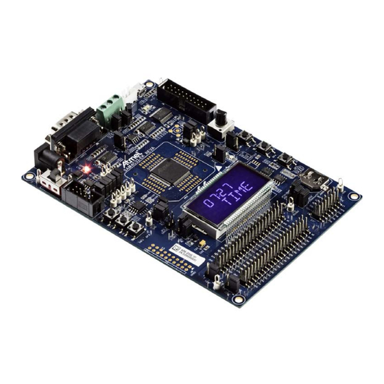
Introduction
The SAM4C32 Evaluation Kit (SAM4C32-EK) enables evaluation capabilities and
code development of applications running on the 32-bit ARM
SAM4C series microcontrollers from Atmel
The SAM4C32-EK can be used with the following microcontrollers:
SAM4C32C
SAM4C16C
SAM4C8C
This document describes the kit contents and architecture, and provides
guidelines on how to use the kit.
Atmel | SMART SAM4C Series
SAM4C32 Evaluation Kit
®
Corporation.
Atmel-11253A-ATARM-SAM4C32-EK-UserGuide_17-Sep-14
USER GUIDE
®
®
Cortex
-M4
Advertisement

Related Manuals for Atmel SMART SAM4C Series


Summary of Contents for Atmel SMART SAM4C Series
- Page 1 Atmel | SMART SAM4C Series SAM4C32 Evaluation Kit USER GUIDE Introduction The SAM4C32 Evaluation Kit (SAM4C32-EK) enables evaluation capabilities and ® ® code development of applications running on the 32-bit ARM Cortex ® SAM4C series microcontrollers from Atmel Corporation. The SAM4C32-EK can be used with the following microcontrollers: SAM4C32C ...
- Page 2 Universal input AC/DC power supply with US, Europe and UK plug adapters ̶ 3V Lithium Battery type CR1225 Cables ̶ Serial RS232 cable ̶ Micro A/B-type USB cable Welcome letter Reference documents SAM4C Series Datasheet (Atmel literature No. 11102) SAM4C32-EK [USER GUIDE] Atmel-11253A-ATARM-SAM4C32-EK-UserGuide_17-Sep-14...
- Page 3 ..............50 SAM4C32-EK [USER GUIDE] Atmel-11253A-ATARM-SAM4C32-EK-UserGuide_17-Sep-14...
- Page 4 The demo software is stored in internal Flash memory. If the content of the internal Flash has been erased, it can ® be reprogrammed recovered to the state as it was when shipped by Atmel using Atmel SAM-BA In-system Programmer available on the Atmel website (www.atmel.com). The binary file of the demo software is also available on the Atmel website.
- Page 5 After boot up, designers can run sample code or their own application on the development kit. Users can download sample code and get technical support from the Atmel website. The SAM4C32-EK is supported by the Atmel Software Framework (ASF) which is also available on the Atmel website.
- Page 6 This section introduces the SAM4C32-EK design. It introduces system-level concepts, such as power distribution, memory, and interface assignments. The Atmel SAM4C32 microcontroller is a system-on-chip solution for smart energy applications, built around two high-performance 32-bit ARM Cortex-M4 RISC processors. These devices operate at a maximum speed of 120 MHz and feature up to 2 Mbyte of embedded Flash, 256 Kbytes of SRAM and on-chip cache for each core.
- Page 7 RS232/RS485 (USART0 RX, TX, RTS, CTS) connected to: ̶ 9-way male D-type RS232 connector ̶ 3-pin connector JTAG/SWD 20-pin IDC connector 5-pin Micro AB USB connector (bridge UART) 3 PIOs connected to HE10 connectors SAM4C32-EK [USER GUIDE] Atmel-11253A-ATARM-SAM4C32-EK-UserGuide_17-Sep-14...
- Page 8 Annotated SAM4C32-EK Board Layout RS232 Interface RS485 Interface Debug Interface Power Supply Power Supply JTAG Interface Zigbee Interface Atmel SAM4C32 System Buttons Atmel Custom LCD User Buttons XPRO Interface Battery Coin Cell PIO Extension PIO Metering PIO Extension Extension SAM4C32-EK [USER GUIDE] Atmel-11253A-ATARM-SAM4C32-EK-UserGuide_17-Sep-14...
- Page 9 PB12 XIN32 PB12 XOUT32 PB13 XOUT32 PB13/AD3 PB14 PB14 PB15 PB15 PB16 PB16 PB17 PB17 PB18 PB18 NRST PB19 ATMEL NRST PB19 PB20 PB20 PB21 PB21 Cortex-M4 Processor PB22 PB22 TMP0 PB23 TMP0 TMP0 PB23/AD4 PB24 SAM4C32 LQFP100 PB24 SHDN...
- Page 10 LCD Voltage Regulator Output VDDLCD 2.5V–3.6V External LCD power supply input (LCD regulator not used) VDDIO/VDDIN need to be supplied when the LCD Controller is used VDDOUT 1.2V Output 120 mA Output Current VDDPLL 1.08V–1.32V – VDDCORE 1.08V–1.32V – SAM4C32-EK [USER GUIDE] Atmel-11253A-ATARM-SAM4C32-EK-UserGuide_17-Sep-14...
- Page 11 BAT54C JP10 VBATT 2.2µF 100nF VDDBU Embedded Memories I2C for data storage in EEPROM (Atmel AT24C1024B) SPI Serial Flash AT45 or AT25F 3.4.1 TWI EEPROM The AT24C1024B provides 1,048,576 bits of serial electrically erasable and programmable read-only memory (EEPROM) organized as 131,072 words of 8 bits each.
- Page 12 90 degrees and are stacked. ® 3.4.3 Adesto Compatible Devices Table 3-3. Compatible Devices ® Adesto AT45DB Series Devices Adesto AT25DF Series Devices AT45DB64D2-CNU AT25DF641A-SH AT45DB321D-MWU AT25DF321A-SH AT45DB131D-SS AT25DF161-SH AT45DB081D-SS AT25DF081-SSH AT45DB041D-SS AT25DF021-SH AT45DB021D-SS – AT45DB011D-SS – SAM4C32-EK [USER GUIDE] Atmel-11253A-ATARM-SAM4C32-EK-UserGuide_17-Sep-14...
- Page 13 Figure 3-11. USART2 RS485 Schematic VDDMAIN VDDMAIN Do Not Populate RS 485 3.3K/DNP ADM3485ARZ VDDMAIN PA9_485 (RXD2) JP14 PA15 100nF (CTS2) PA14 (RTS2) PA10 (TXD2) PA9_485 JP16 JP15 120R JP17 FGND Do Not Populate PA9_232 3.3K/DNP SAM4C32-EK [USER GUIDE] Atmel-11253A-ATARM-SAM4C32-EK-UserGuide_17-Sep-14...
- Page 14 Serial Port Schematic UART1 VDDMAIN ADM3312EARU 4.7µF 100nF 100nF 100nF 100nF Do Not Populate 100nF VDDMAIN 47K/DNP 100nF (RS232_TXD) (TXD1) T1IN T1OUT (RS232_RXD) (RXD1) R1OUT R1IN T2IN T2OUT VDDMAIN R2OUT R2IN HE10 T3IN T3OUT R3OUT R3IN SAM4C32-EK [USER GUIDE] Atmel-11253A-ATARM-SAM4C32-EK-UserGuide_17-Sep-14...
- Page 15 The SAM4C32-EK includes a JTAG interface port to provide debug level access to the system-on-chip. The JTAG port is a 20-pin, dual-row, 0.1-inch male connector. This port provides the required interface for in-circuit emulators ® such as the ARM Multi-ICE and Atmel SAM-ICE. Features: One HE10 20-pin male connector ...
- Page 16 SPI CLK Power Ground Power Supply 3.7.2 REB233-XPRO Interface The XPRO interface connects with new Atmel modules used for XPRO platforms that are equipped with a 20-pin HE14 male connector. Figure 3-16. XPRO Interface Schematic HE14 100-mil right angled male DNP...
- Page 17 49R9 LED+ LED- 100nF R104 10µF IRLML6401 4.7K PB22 R106 R106 PB21 PA13 PB20 100R PB19 74HC4066 VDDMAIN C83 100nF R115 R116 R117 Do Not Populate R118 PB18 R119 R120 PB17 R121 PB16 R122 PB15 74HC4066 SAM4C32-EK [USER GUIDE] Atmel-11253A-ATARM-SAM4C32-EK-UserGuide_17-Sep-14...
- Page 18 D0-a D0-b D0-c D0-p A1-h A1-i A1-k A1-n D0-f D0-g D0-e D0-d A1-f A1-e A1-d A6-h A6-i A6-k A6-n A1-a A1-b A1-c A6-f A6-e A6-d A1-g A1-j A1-L A1-m A6-a A6-b A6-c A0-h A0-i A0-k A0-n SAM4C32-EK [USER GUIDE] Atmel-11253A-ATARM-SAM4C32-EK-UserGuide_17-Sep-14...
- Page 19 SEG20 PB21 PB20 SEG21 SEG22 PB19 PB18 SEG23 SEG24 PB17 PB16 SEG25 SEG26 PB15 PB14 SEG27 SEG28 PB13 PB12 SEG29 SEG30 PB11 PB10 SEG31 SEG32 SEG33 SEG34 SEG35 SEG36 PA28 PA27 SEG37 SEG38 PA26 PA23 SEG39 SAM4C32-EK [USER GUIDE] Atmel-11253A-ATARM-SAM4C32-EK-UserGuide_17-Sep-14...
- Page 20 Analog Input One VR1 multi-turn 10K Ω potentiometer is connected to the jumper JP4. If JP4 is closed, this analog reference is available on analog input PA4. Figure 3-20. Analog Input Schematic VDDIN (Analog input) 10nF SAM4C32-EK [USER GUIDE] Atmel-11253A-ATARM-SAM4C32-EK-UserGuide_17-Sep-14...
- Page 21 3.9.3 Temperature Sensor The Atmel AT30TS75 temperature sensor converts temperatures from -40°C to +125°C to a digital word and provides a typical accuracy of ±0.5°C over the operating temperature range of 0°C to +85°C. The device is factory calibrated and requires no external components to help provide a cost effective solution. To reduce current consumption and save power, the AT30TS75 features a shutdown mode that turns off all internal circuitry except for the internal power-on reset and serial interface circuits.
- Page 22 JTAG in 2-wire mode (SWIO and SWD) due to the loss of the TDO pin. In this case, TMP2 is pull-up at RTCOUT Level (PB1 pin) and can be managed dynamically synchronized with the RTCOUT pin. SAM4C32-EK [USER GUIDE] Atmel-11253A-ATARM-SAM4C32-EK-UserGuide_17-Sep-14...
- Page 23 This board includes an additional connector which allows connecting to an external board through the SPI 1 port. Figure 3-26. Connector Schematic VDDMAIN JP23 R139 R141 (TXD1) R140 R142 (RXD1) R143 R144 R145 PA29 (MCLK) PIOsense SAM4C32-EK [USER GUIDE] Atmel-11253A-ATARM-SAM4C32-EK-UserGuide_17-Sep-14...
- Page 24 – – PA27 – – NCS0 SEG21 – – PA28 – – SEG22 – – PA29 PCK1 – NWAIT SEG23 – – MCLK (ATSense) PA30 PCK1 – – XOUT XOUT – PA31 PCK0 – – – SAM4C32-EK [USER GUIDE] Atmel-11253A-ATARM-SAM4C32-EK-UserGuide_17-Sep-14...
- Page 25 – PIO, I, PD, ST PB27 – – SEG45 WKUP14 – PB28 – – SEG46 WKUP15 – PB29 – – SEG47 – – PB30 – – SEG48 – – PB31 – – A0–NBS0 SEG49/AD5 – – SAM4C32-EK [USER GUIDE] Atmel-11253A-ATARM-SAM4C32-EK-UserGuide_17-Sep-14...
- Page 26 The maximum input voltage that can be applied on this connector must be lower than 6V. Figure 3-27. Power Supply Connector Table 3-11. Power Supply Connector Pinout Signal Name Description Wall Adapter Main Voltage Floating Point Ground SAM4C32-EK [USER GUIDE] Atmel-11253A-ATARM-SAM4C32-EK-UserGuide_17-Sep-14...
- Page 27 JTAG data output from target CPU (serial data input from the target). Typically TDO JTAG TEST DATA OUTPUT connected to TDO on target CPU. nSRST RESET Active-low reset signal. Target CPU reset signal This pin is not connected in SAM-ICE This pin is not connected in SAM-ICE SAM4C32-EK [USER GUIDE] Atmel-11253A-ATARM-SAM4C32-EK-UserGuide_17-Sep-14...
- Page 28 RS232 Connector Pinout Signal Name Description 1, 4, 6, 9 Not Connected RS232 Serial Data Output Signal RS232 Serial Data Input Signal Common Ground Request To Send - Not Used Clear To Send - Not Used SAM4C32-EK [USER GUIDE] Atmel-11253A-ATARM-SAM4C32-EK-UserGuide_17-Sep-14...
- Page 29 Micro AB USB Connector 1 2 3 4 5 Table 3-14. Micro AB USB Connector Pinout Signal Name Description VBUS 5V Power Data Minus Data Plus On The Go Identification Common Ground 6, 7, 8, 9 Shield Mechanical Pins SAM4C32-EK [USER GUIDE] Atmel-11253A-ATARM-SAM4C32-EK-UserGuide_17-Sep-14...
- Page 30 Socket J12 Table 3-15. Socket Pinout Function Signal Name Signal Name Function Reset /RST IRQ0 Interrupt Request Interrupt Request IRQ1 SLP_TR SLP_TR SPI Chip Select MOSI SPI MOSI SPI MISO MISO SCLK SPI CLK Power Supply SAM4C32-EK [USER GUIDE] Atmel-11253A-ATARM-SAM4C32-EK-UserGuide_17-Sep-14...
- Page 31 Power Supply VDDMAIN VDDMAIN Power Supply Table 3-17. Expansion Port J10 Pinout Function Signal Name Signal Name Function 3.3V or 5V – – 3.3V or 5V Ground Ground – PA16 – – PA17 – – PA18 – SAM4C32-EK [USER GUIDE] Atmel-11253A-ATARM-SAM4C32-EK-UserGuide_17-Sep-14...
- Page 32 Power Supply VDDMAIN VDDMAIN Power Supply Figure 3-33. Expansion Port J12 Table 3-18. Expansion Port J12 Pinout Power Power – 3.3V 3.3V – – – – – – – – – – – PA29 – – SAM4C32-EK [USER GUIDE] Atmel-11253A-ATARM-SAM4C32-EK-UserGuide_17-Sep-14...
- Page 33 Anti-Tamper BP3 Push Button Two-wire Interface Temperature Sensor AT30TS75 Segmented LCD Custom Atmel Display SAM4C32 Core 1 — 10-bit ADC Internal ADC channel connected to Battery Backup Power Rail (VDDBU) After the first power-up without the backup battery, the time (hour and minute) of the RTC can be configured. The Hour and Minute settings are entered using the following push buttons: BP4 (SCROLL_UP)—sets the Hour (24H mode entries must be made)
- Page 34 SAM4C32 Microcontroller and its crystals, decoupling capacitors and analog inputs Power Supplies Distribution RS232, RS485 and DBGU Interfaces, TWI Memories, and Temperature Sensor Custom Glass LCD and ZigBee, XPRO interfaces User Buttons, I/O expansion headers and JTAG Interfaces SAM4C32-EK [USER GUIDE] Atmel-11253A-ATARM-SAM4C32-EK-UserGuide_17-Sep-14...
- Page 35 Figure 5-1. SAM4C32-EK Schematic (Page 1 of 7) SAM4C32-EK [USER GUIDE] Atmel-11253A-ATARM-SAM4C32-EK-UserGuide_17-Sep-14...
- Page 36 Figure 5-2. SAM4C32-EK Schematic (Page 2 of 7) SAM4C32-EK [USER GUIDE] Atmel-11253A-ATARM-SAM4C32-EK-UserGuide_17-Sep-14...
- Page 37 Figure 5-3. SAM4C32-EK Schematic (Page 3 of 7) SAM4C32-EK [USER GUIDE] Atmel-11253A-ATARM-SAM4C32-EK-UserGuide_17-Sep-14...
- Page 38 Figure 5-4. SAM4C32-EK Schematic (Page 4 of 7) SAM4C32-EK [USER GUIDE] Atmel-11253A-ATARM-SAM4C32-EK-UserGuide_17-Sep-14...
- Page 39 Figure 5-5. SAM4C32-EK Schematic (Page 5 of 7) SAM4C32-EK [USER GUIDE] Atmel-11253A-ATARM-SAM4C32-EK-UserGuide_17-Sep-14...
- Page 40 Figure 5-6. SAM4C32-EK Schematic (Page 6 of 7) SAM4C32-EK [USER GUIDE] Atmel-11253A-ATARM-SAM4C32-EK-UserGuide_17-Sep-14...
- Page 41 Figure 5-7. SAM4C32-EK Schematic (Page 7 of 7) SAM4C32-EK [USER GUIDE] Atmel-11253A-ATARM-SAM4C32-EK-UserGuide_17-Sep-14...
- Page 42 (Figure 5-12 on page Layer 6: Bottom Layer (Figure 5-13 on page TOP Components Placement (Figure 5-14 on page BOTTOM Components Placement (Figure 5-15 on page Figure 5-8. SAM4C32-EK Layout: Top Layer SAM4C32-EK [USER GUIDE] Atmel-11253A-ATARM-SAM4C32-EK-UserGuide_17-Sep-14...
- Page 43 Figure 5-9. SAM4C32-EK Layout: Ground Layer SAM4C32-EK [USER GUIDE] Atmel-11253A-ATARM-SAM4C32-EK-UserGuide_17-Sep-14...
- Page 44 Figure 5-10. SAM4C32-EK Layout: Internal Signals 1 Layer SAM4C32-EK [USER GUIDE] Atmel-11253A-ATARM-SAM4C32-EK-UserGuide_17-Sep-14...
- Page 45 Figure 5-11. SAM4C32-EK Layout: Internal Signals 2 Layer SAM4C32-EK [USER GUIDE] Atmel-11253A-ATARM-SAM4C32-EK-UserGuide_17-Sep-14...
- Page 46 Figure 5-12. SAM4C32-EK Layout: Power Supplies Layer SAM4C32-EK [USER GUIDE] Atmel-11253A-ATARM-SAM4C32-EK-UserGuide_17-Sep-14...
- Page 47 Figure 5-13. SAM4C32-EK Layout: Bottom Layer SAM4C32-EK [USER GUIDE] Atmel-11253A-ATARM-SAM4C32-EK-UserGuide_17-Sep-14...
- Page 48 Figure 5-14. SAM4C32-EK Layout: TOP Components Placement SAM4C32-EK [USER GUIDE] Atmel-11253A-ATARM-SAM4C32-EK-UserGuide_17-Sep-14...
- Page 49 Figure 5-15. SAM4C32-EK Layout: BOTTOM Components Placement SAM4C32-EK [USER GUIDE] Atmel-11253A-ATARM-SAM4C32-EK-UserGuide_17-Sep-14...
- Page 50 Revision History Table 6-1. Revision History Doc. Rev. Date Changes 17-Sep-2014 First issue SAM4C32-EK [USER GUIDE] Atmel-11253A-ATARM-SAM4C32-EK-UserGuide_17-Sep-14...
- Page 51 DISCLAIMER: The information in this document is provided in connection with Atmel products. No license, express or implied, by estoppel or otherwise, to any intellectual property right is granted by this document or in connection with the sale of Atmel products. EXCEPT AS SET FORTH IN THE ATMEL TERMS AND CONDITIONS OF SALES LOCATED ON THE ATMEL WEBSITE, ATMEL ASSUMES NO LIABILITY WHATSOEVER AND DISCLAIMS ANY EXPRESS, IMPLIED OR STATUTORY WARRANTY RELATING TO ITS PRODUCTS INCLUDING, BUT NOT LIMITED TO, THE IMPLIED WARRANTY OF MERCHANTABILITY, FITNESS FOR A PARTICULAR PURPOSE, OR NON-INFRINGEMENT.
Need help?
Do you have a question about the SMART SAM4C Series and is the answer not in the manual?
Questions and answers