Advertisement
Quick Links
Advertisement

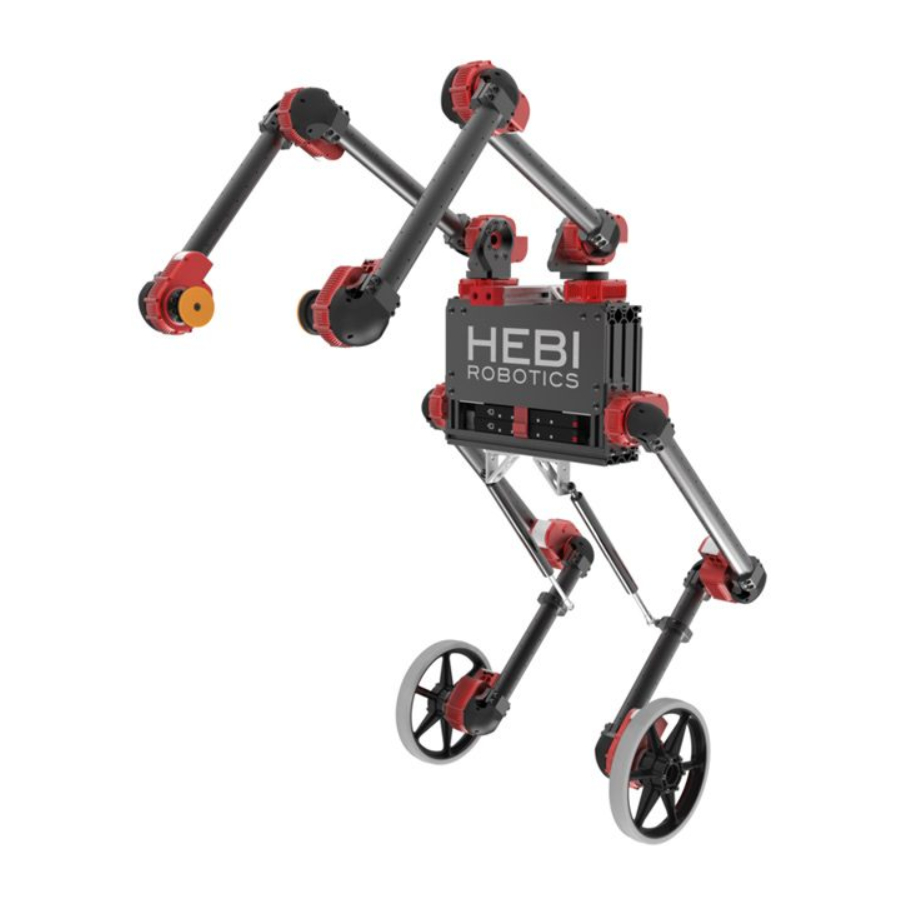
Summary of Contents for HEBI Robotics IGOR II
- Page 1 IGOR II 14 DoF Wheeled R/C Robot Assembly Instructions Updated Aug. 22, 2018...
-
Page 2: General Warnings And Cautions
- X8: 7mm tap depth • Use provided hardware with accessories and hand tighten as needed. • Do not attempt to disassemble actuator, this will void the warranty and can cause permanent damage. For more information please visit: docs.hebi.us X-Series IGOR II Assembly Instructions... - Page 3 Robot Workspace X-Series IGOR II Assembly Instructions...
- Page 4 X5-9 X8-3 A-2039-02 A-2038-02 A-2090-01 A-2043-01 A-2091-01 -2088-140-20 A-2188-01 -2040-01 -2040-01 [Gas Spring – 20lbs.] PM-2200-02 PM-2200-03_Cut A-2061-03 [300mm] [350mm] Igor II Chassis -2067-01 A-2076-08 8” Wheel and Adapter Disk Grippers fasteners included, not shown X-Series IGOR II Assembly Instructions...
- Page 5 Power Distribution Board Ethernet Coupler LiGo Battery A-2046-12 A-2046-18 A-2046-24 Power Cable, 12” Length Power Cable, 18” Length Power Cable, 24” Length PP-2062-01 PP-2059-01 PP-2060-01 Ethernet Cable, 48” Length Ethernet Cable, 12” Length Ethernet Cable, 24” Length X-Series IGOR II Assembly Instructions...
-
Page 6: Wiring Notes
These fit well within the tubes between actuators. directly to actuator ports. Wires that connect to the next joint should be threaded through the actuator’s bore hole. X-Series IGOR II Assembly Instructions... - Page 7 Table of Contents Assembly Quantity Image Pages Chassis [8-10] 1x Left Arms [11-20] 1x Right Legs [21-29] 2x Mirrored Final [30-33] (includes wiring) X-Series IGOR II Assembly Instructions...
- Page 8 Chassis X-Series IGOR II Assembly Instructions...
-
Page 9: Chassis Wiring
Chassis Wiring Legend *Cabling will be provided with assembled chassis Power Cable Ethernet Cable Battery Right Arm Left Arm Right Leg Left Leg X-Series IGOR II Assembly Instructions... - Page 10 Chassis Bulkhead Layout X-Series IGOR II Assembly Instructions...
- Page 11 “ ” “ f ” Arms (1x Left & 1x Right) X-Series IGOR II Assembly Instructions...
- Page 12 Flat face towards inside 1x L 1x R -2040-01L -2040-01R Align with actuator output hub tick mark (face parallel with tick mark and X-Series IGOR II Assembly Instructions mounting hole pointed on same side)
- Page 13 1x L 1x L 1x R 1x R X-Series IGOR II Assembly Instructions...
- Page 14 PM-2200-02 -2039-02 -2038-02 [300mm] X-Series IGOR II Assembly Instructions...
- Page 15 PM-2200-02 -2039-02 -2038-02 [300mm] X-Series IGOR II Assembly Instructions...
- Page 16 1x L 1x R 1x L 1x R A-2090-01 Align with actuator output hub tick mark (Tube aligns with tick mark) X-Series IGOR II Assembly Instructions...
- Page 17 1x L 1x R 1x L 1x R Align with actuator output hub tick mark (Tube aligns with tick mark) X-Series IGOR II Assembly Instructions...
- Page 18 1x L 1x R -2067-01 Disk Grippers X-Series IGOR II Assembly Instructions...
- Page 19 1x L 1x R A-2091-01 A-2090-01 Install cables before adding covers X-Series IGOR II Assembly Instructions...
- Page 20 ” Right Elbow ” ” ” ” ” ” Right Shoulder Right Wrist ” To Left Arm ” ” Legend Power Cable Right Base Ethernet Cable Power Distribution To Right Leg To Chassis Ethernet Coupler X-Series IGOR II Assembly Instructions...
- Page 21 *Refer to Wiring Notes (pg. 6)* Left Elbow ” ” ” ” ” ” Left Shoulder Left Wrist ” ” Legend Left Base Power Cable From Right Arm Ethernet Cable Power Distribution ” To Chassis Ethernet Coupler To Left Leg X-Series IGOR II Assembly Instructions...
- Page 22 “ ” “ f ” Legs X-Series IGOR II Assembly Instructions...
- Page 23 -2043-01 X-Series IGOR II Assembly Instructions...
- Page 24 2x 350mm PM-2200-03_Cut -2039-02 -2038-02 [350mm] X-Series IGOR II Assembly Instructions...
- Page 25 2x 350mm Align with actuator output hub tick mark (Tube aligns with tick mark) X-Series IGOR II Assembly Instructions...
- Page 26 2x 300mm PM-2200-02 -2039-02 -2038-02 [300mm] X-Series IGOR II Assembly Instructions...
- Page 27 2x 300mm Align with actuator output hub tick mark (Tube aligns with tick mark) 8-16 X-Series IGOR II Assembly Instructions...
- Page 28 A-2076-08 8” Wheel and Adapter X-Series IGOR II Assembly Instructions...
- Page 29 A-2091-01 A-2090-01 Install cables before adding covers X-Series IGOR II Assembly Instructions...
- Page 30 To NUC *Refer to Wiring Notes (pg. 6)* ” To Chassis ” ” To Left Arm ” Left Hip ” ” Left Knee ” Legend Power Cable ” Ethernet Cable Power Distribution Ethernet Coupler Left Wheel X-Series IGOR II Assembly Instructions...
- Page 31 Right Leg Wiring ” *Refer to Wiring Notes (pg. 6)* ” To Right Arm ” Right Hip ” ” ” Right Knee ” ” Legend Power Cable Ethernet Cable Power Distribution Right Wheel Ethernet Coupler X-Series IGOR II Assembly Instructions...
-
Page 32: Final Assembly
Final Assembly X-Series IGOR II Assembly Instructions... - Page 33 -2088-140-20 A-2188-01 [Gas Spring – 20lbs.] X-Series IGOR II Assembly Instructions...
- Page 34 X-Series IGOR II Assembly Instructions...
- Page 35 Wiring through Chassis (Robot facing you) Left Elbow Right Elbow Left Shoulder Left Wrist Right Shoulder Right Wrist Left Base Right Base Chassis Right Hip Left Hip Legend Left Knee Power Cable Right Knee Ethernet Cable Power Distribution Ethernet Coupler Router Right Wheel LeftWheel...
- Page 36 © HEBI Robotics 2018...


Need help?
Do you have a question about the IGOR II and is the answer not in the manual?
Questions and answers