Advertisement
Quick Links
Advertisement

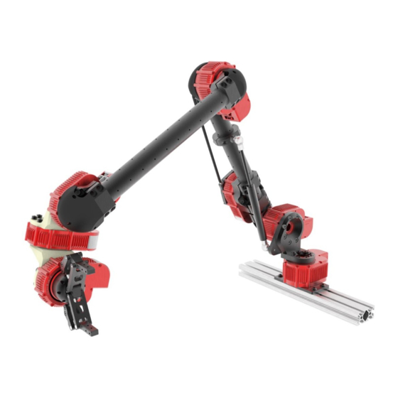
Summary of Contents for HEBI Robotics X Series
- Page 1 6-DoF Arm Kit Assembly Instructions...
-
Page 2: General Warnings And Cautions
General Warnings and Cautions Danger (May cause serious injury or death) • Keep water, flammables, solvents and other liquids clear from actuator. • Never place fingers, arms, toes and other body parts near actuator during operation. • Cut power if actuator emits strange odors or smoke. •... -
Page 3: Technical Specifications
Technical Specifications Specifications Value Movement Working Range Speed Weight (w/ Gripper Assembly) 4.75 kg Axis 1 – Base Continuous 180°/s [Default: X8-9] (limited by wiring) Max Reach 750 mm Axis 2 – Shoulder 0°to +70° 90°/s Payload @ Max Reach 0.60 kg [Default: X8-16] (limited by gas spring) - Page 4 Technical Specifications Spool Max Finger Force at Max Finger Torque Module 50mm X5-1 0.1 Nm X5-4 0.5 Nm 10 N 82mm X5-9** 1.1 Nm 23 N 105.35mm *Values assume a symmetric two-finger grasp ** Default Module *** Only X5 Modules can be used for the spool 10mm 4 X M3 THRU 10mm...
- Page 5 Bill of Materials - Mechanical Default Configuration X8-16 X8-9 X5-1 X5-9 A-2055-01 PP-2239-01 -2038-02 -2090-01 -2039-02 -2091-01 -2200-02 -2088-90-30 A-2188-01 -2043-01 -2040-01R -2042-01R [300mm] (Gas Spring – 30lbs.) PM-2222-01 PP-2241-01 PP-2240-01 PM-2293-01 PM-2292-01 PM-2290-01 Cable Housing Adapter Cable Housing End Cap Cable Housing Spool Housing Spool...
- Page 6 Bill of Materials - Electrical A-2128-01 A-2048-02 Power Distribution Board Power Jumper A-2046-12 A-2046-18 A-2046-24 Power Cable, 12” Length Power Cable, 18” Length Power Cable, 24” Length PP-2059-01 PP-2061-01 Ethernet Cable, 12” Length Ethernet Cable, 36” Length X-Series 6-DoF Arm Assembly Instructions...
- Page 7 Table of Contents Assembly Image Pages Tubes Base [9-10] [11-15] Gripper [16-21] Final [22-30] X-Series 6-DoF Arm Assembly Instructions...
- Page 8 M5x16mm PP-2200-02 M5x16mm [300mm] A-2038-02 A-2039-02 X-Series 6-DoF Arm Assembly Instructions...
- Page 9 Flat face towards outside M5x12mm Step 2 of 2 X8-9 A-2040-01R M6x12mm Step 1 of 2 Axis 1: Base Default X8-9 M5x10mm FHCS Align with actuator output hub tick mark (face parallel with tick mark and X-Series 6-DoF Arm Assembly Instructions mounting hole pointed on same side)
- Page 10 Axis 2: Shoulder Default X8-16 X8-16 M5x14mm X-Series 6-DoF Arm Assembly Instructions...
- Page 11 M5x16mm Align with actuator output hub tick mark (Tube aligns with tick mark) M5x10mm A-2088-90-30 A-2188-01 (Gas Spring – 30lbs.) Gas springs require washer for flush mounting (included in A-2088-90-30) X-Series 6-DoF Arm Assembly Instructions...
- Page 12 Axis 3: Elbow Default X8-9 5x8mm 5x10mm X8-9 Align with actuator output hub tick mark (Tube aligns with tick mark) X-Series 6-DoF Arm Assembly Instructions...
- Page 13 Align with actuator output hub tick mark X5-1 A-2042-01R Axis 4: Wrist 1 5x10mm Default X5-1 5x12mm 5x8mm Axis 5: Wrist 2 Default X5-1 X-Series 6-DoF Arm Assembly Instructions...
- Page 14 Align with actuator output hub tick mark X5-1 A-2042-01R 5x10mm Axis 6: Wrist 3 Default X5-1 5x12mm X-Series 6-DoF Arm Assembly Instructions...
- Page 15 All axes at zero degrees X-Series 6-DoF Arm Assembly Instructions...
- Page 16 Gripper X-Series 6-DoF Arm Assembly Instructions...
- Page 17 Spool Default X5-9 X-Series 6-DoF Arm Assembly Instructions...
- Page 18 M5x12mm PM-2293-01 PM-2292-01 M3x35mm Spool Housing Spool Clocking for the Spool does not matter X-Series 6-DoF Arm Assembly Instructions...
- Page 19 M5x8mm PM-2290-02 Housing Horizontal Tube Adapter X-Series 6-DoF Arm Assembly Instructions...
- Page 20 PM-2148-01 Tube Clamp X-Series 6-DoF Arm Assembly Instructions...
- Page 21 The Last Module on the Arm M5x8mm Align with actuator output hub tick mark X-Series 6-DoF Arm Assembly Instructions (Fingers perpendicular to the tick mark)
-
Page 22: Wiring Notes
Wiring Notes • Keeping wires organized will help prevent tangling and add a nice aesthetic. • Spiral sleeving is a good accessory for organizing loose wires • HEBI X-Series actuators have a thru bore specifically designed to fit ethernet and power connectors. •... -
Page 23: Wiring Diagram
Wiring Diagram 36” Elbow 12” 18” 12” 12” Spool 12” 36” 18” 12” 12” Wrist 1 Power Cable 12” Ethernet Cable 12” 18” Shoulder Power Distribution 18” Power Jumper 24” 24” Power Supply Wrist 2 Wrist 3 36” Base network X-Series 6-DoF Arm Assembly Instructions... - Page 24 Wiring Diagram (no Spool Module) 36” Elbow 12” 18” 12” 12” 36” 12” 12” Wrist 1 Power Cable 12” Ethernet Cable 12” 18” Shoulder Power Distribution 18” Power Jumper 24” 24” Power Supply Wrist 2 Wrist 3 36” Base network X-Series 6-DoF Arm Assembly Instructions...
- Page 25 Running the Cable Through • Make sure to use a Standard Road Bike Brake Cable. • Run the cable to fit your system. • Run both the cable and the cable housing before cutting them to ensure that the cable is long enough. •...
- Page 26 PP-2240-01 PP-2239-01 Cable Housing Cable PM-2222-01 Cable Housing Adapter X-Series 6-DoF Arm Assembly Instructions...
- Page 27 Gripper Cable Routing X-Series 6-DoF Arm Assembly Instructions...
- Page 28 X-Series 6-DoF Arm Assembly Instructions...
- Page 29 PM-2290-01 Cable Clamp M3x8mm X-Series 6-DoF Arm Assembly Instructions...
- Page 30 2x8mm 2x8mm A-2090-01 A-2090-01 A-2091-01 2x8mm Install cables before adding caps 2x8mm 2x8mm X-Series 6-DoF Arm Assembly Instructions...
-
Page 31: Additional Accessories
Additional Accessories • Power Supply, 24V 220W (A-2098-24) • Comes with correct Molex Minifit Jr 2 connector • Magnet embedded end effector (A-2081-01) • Interfaces with hex shaft driver bits for screwing/bolting tasks • Screwdriver bits not included • HEBI I/O Board (A-2116-01) •... - Page 32 © HEBI Robotics 2018 X-Series 6-DoF Arm Assembly Instructions...


Need help?
Do you have a question about the X Series and is the answer not in the manual?
Questions and answers