Table of Contents

Related Manuals for ZKTeco G4 Pro Series:


Summary of Contents for ZKTeco G4 Pro Series:
- Page 1 Quick Start Guide Applicable Model: G4 Pro Series Version: 1.1 Due to regular upgrades of systems and products, ZKTeco could not guarantee exact consistency between the actual product and the written information in this manual.
-
Page 2: Safety Precautions
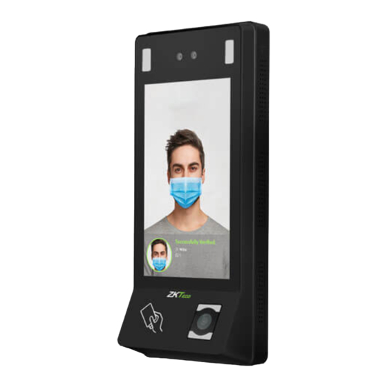
Safety Precautions Before installation, please read the following precautions carefully to prevent the risks and danger to this product, users or any other person. Do not expose to direct sunlight, water, dust and soot. Do not place any magnetic objects near the product. Magnetic objects such as magnets, CRT, TV, monitors or speakers may damage the device. - Page 3 Overview Visible light camera Thermal imaging temperature detection module IR camera IR LED 7 Inch HD capacitive touch screen Speaker Microphone QR code sensor Fingerprint sensor Card reader Reset button USB port +12V Auxiliary Power in input Sensor Exit button +12V Power out 485B...
-
Page 4: Installation
Dimensions G4 Pro G4 Pro[TI] 264.45mm 319.30mm 184.25mm 184.25mm 136.50mm 136.50mm 119.95mm 54.86mm 79.50mm 65.68mm 119.95mm 54.86mm 79.50mm 65.68mm Installation G4 Pro and G4 Pro[TI] installation are the same, the following is an example of G4 Pro[TI]. Choose whether to use Backplate or Back Cover to install the device. With Backplate Mounting Hole Mounting Hole... - Page 5 With Back Cover Back Cover is divided into right-tilt installation or left-tilt installation, the following is an example of right-tilt installation: G4 Pro Mounting template (Only for your reference) NOTE: Mounting Hole Tilted to the left Tilted to the right Mounting Hole Mounting Hole Mounting Hole...
-
Page 6: Standalone Installation
Standalone Installation Option A Option B Switch TCP/IP Door Sensor Alarm Lock Exit Button Power Connection PoE Connection Connect the device with an 8-core network cable. Power Network Operator PoE Switch Cat5E Ethernet cable... -
Page 7: Dc Supply Connection
12V DC Supply Connection 12V DC Recommended power supply Rating of 12V and 3A To share the device’s power with other devices, use a power supply with higher current ratings. Lock Relay Connection The system supports both Normally Opened Lock and Normally Closed Lock. The NO Lock (normally opened when powered) is connected with ‘NO’... -
Page 8: Connecting Other Devices
Connecting Other Devices Button & Sensor Connection Door Sensor No Touch EXIT Exit Button Alarm & RS485 Connection 485 Reader 485- 485B 485+ 485A Alarm Alarm power Wiegand Connection +12V IWD0 Wiegand Device Wiegand In Port IWD1 Wiegand Reader... -
Page 9: Lan Connection
Ethernet, 4G & Wi-Fi Connection LAN Connection Click [System Settings] > [Network settings] > [TCP/IP settings] > Enable ethernet to set the IP Address. 4G Connection Click [System Settings] > [Network settings] > [Mobile network] and enable the Mobile data. Note: You need to provide your own SIM card, use a screwdriver to unscrew the card slot on the back of the device. - Page 10 Enroll New User Click on > User Management > to register a new user. The options include entering the User ID and Name, setting User Role, registering Palm, Card Number, Password, Face, Fingerprint and setting Access Control Role. Note: Normal User is not authorized to operate the menu options of the device. Only super administrator can operate all the menu options of the device.
-
Page 11: Network Settings
Network Settings TCP/IP settings Click on > System Settings > Network settings > Enable ethernet to set the IP Address. The device will communicate with the PC via the Ethernet parameters. Wi-Fi Settings Click on > System Settings > Network settings > Wireless network. Click on the appropriate Wi-Fi name from the available list, and input the correct password in the password interface. - Page 12 Click on > System Settings > Network settings > Mobile data to enable the mobile network. Cloud Service Settings Click on > System Settings > Cloud service settings to set the server address and server port, that is, the IP address and port number of the server after the software is installed. If the device communicates with the server successfully, the icon will be displayed in the upper right corner of the standby interface.
-
Page 13: Access Control
Access Control Click on > Access Control > Access Control Options to enter access control options setting interface and set relevant parameters of the access control. Date and Time Settings Click on > System Settings > Date and time enter date and time setting interface to set the relevant parameters. - Page 14 Detection Management ❶ ❶ ❷ ❷ ❶ Click on > System Settings > Detection management to enter the setting interface. ❶ You can set the value of High temperature alarm threshold, and enable the Temperature over the range access denied and the Trigger external alarm, the device will send an alarm prompt when the temperature of the user detected exceeds this value, meanwhile the user will be forbidden to access, as shown in the following figure.
- Page 15 QR Code Scanner Click on > System Settings > Access control record settings > QRCode. If it is enabled, the camera can recognize the QR code image on the ZKBioSecurity Mobile APP captured by the lens or the QR code scanner. Find the access control QR code on the ZKBioSecurity Mobile App.
-
Page 16: Troubleshooting
Attendance Record Search View attendance records in the device: Click on > Attendance Search > Access Logs enter Name or Employee ID > select Time Range > press OK, the corresponding access logs will be displayed. Note: If the User ID field is left blank, records of all users will be displayed. View attendance records on computer: Click on >... - Page 17 ZKTeco Industrial Park, No. 32, Industrial Road, Tangxia Town, Dongguan, China. Phone : +86 769 - 82109991 : +86 755 - 89602394 www.zkteco.com Copyright © 2022 ZKTECO CO., LTD. All Rights Reserved.
Need help?
Do you have a question about the G4 Pro Series: and is the answer not in the manual?
Questions and answers