
Related Manuals for Soyer UVR-300


Summary of Contents for Soyer UVR-300
- Page 1 Operating Instructions UVR-300 universal feeder UVR-400 universal feeder GB: English ersion Read these operating instructions before starting any work! Date of issue:04.2021 Doc.ID: P00250 www.soyer.com...
- Page 2 UVR-300 Universal feeder UVR-400 Operating Instructions Document no: P00250, 04-2021, translation of the original German instructions (German: P00150) All information contained in this document is the property of Heinz Soyer Bolzenschweißtechnik GmbH. Revision status Document created / modified Editor Date...
-
Page 3: Table Of Contents
Cleaning the devices ......................33 Converting the universal feeder ..................34 7.1.1 Conversion set for M3 - M8 (preferably for UVR-300) ............. 34 7.1.2 Conversion set for UVR-400 (M10, M12 and Ø 10.8) ............. 35 Carrying out the conversion ....................36 Adjusting the step width ....................... - Page 4 Warranty conditions......................59 Spare and wear parts ......................60 12.1 Feeder conversion set (M3 - M8) ..................60 12.2 Individual parts for the UVR-400 conversion set (M10, M12 and Ø 10.8) ......62 Operating instructions UVR-300/UVR-400 | Heinz Soyer Bolzenschweißtechnik...
-
Page 5: General Information
Keep the operating instructions in a readily accessible location close to your devices. The term 'Devices' in the operating instructions refers to the UVR-300 and UVR-400 universal feeders. Carefully read the operating instructions and any other documents contained in the technical documentation. - Page 6 Conformity declaration – Universal Feeder Operating instructions UVR-300/UVR-400 | Heinz Soyer Bolzenschweißtechnik...
-
Page 7: Manufacturer
DIN EN 60974-9 Arc welding equipment - Installation and use Technical Bulletin DVS 0904 Instruction for practice - Arc stud welding Operating instructions UVR-300/UVR-400 | Heinz Soyer Bolzenschweißtechnik... -
Page 8: Important Safety Instructions
Do not touch or open, danger to unauthorised persons. Danger to persons with medical implants such as pacemakers. The information sign is not a warning sign. It indicates important and useful information on the subject. Operating instructions UVR-300/UVR-400 | Heinz Soyer Bolzenschweißtechnik... -
Page 9: General Safety Instructions
Starting the device with faulty protective devices is not permitted. Faulty protective devices must be repaired or replaced immediately. Unintentional operation by third parties must be prevented. Operating instructions UVR-300/UVR-400 | Heinz Soyer Bolzenschweißtechnik... - Page 10 Explosion hazard due to inappropriate installation location in a potentially explosive atmosphere The device is not designed for use in potentially explosive zones. The device must not be installed and operated in potentially explosive atmospheres. Operating instructions UVR-300/UVR-400 | Heinz Soyer Bolzenschweißtechnik...
- Page 11 Fire hazard from hot welding spatter Welding spatter or hot workpieces produced during the welding process can result in fire hazard. Do not store combustible or highly inflammable materials in the welding area. Operating instructions UVR-300/UVR-400 | Heinz Soyer Bolzenschweißtechnik...
-
Page 12: Safety Information For Universal Feeder Uvr-300 / Uvr-400
Safety information for universal feeder UVR-300 / UVR-400 In addition to the general safety information in these instructions, the following safety information applies to handling the devices: Risk due to accelerated welding studs The welding studs are transported using compressed air and are therefore greatly accelerated. -
Page 13: Personal Protective Equipment
Welding spatters occur during the welding process. Wear appropriate, non-combustible, heat-resistant safety footwear. Hearing protection Depending on the welding device and the welding application, relatively loud welding noises may occur. In that case, wear appropriate hearing protection. Operating instructions UVR-300/UVR-400 | Heinz Soyer Bolzenschweißtechnik... -
Page 14: Intended Use Of The Stud Welding Systems
Intended use of the stud welding systems The devices (universal feeders UVR-300 and UVR-400) described here require additional components for automatic operation. Stud welding device with feeder interface, e.g. BMS-9 Automatic Automatic stud welding gun or head Typical application areas for the automatic feed of welding fasteners are as follows: ... -
Page 15: Requirements On The Part Of The Operator
The following generally applies: Work on live elements may only be performed by authorised electricians. This work must be performed in line with the applicable technical rules for electrotechnical devices. All devices of Soyer Bolzenschweißtechnik GmbH must only be opened by ® ®... -
Page 16: Transport
Local environmental directives must be observed when disposing of the device. Water-endangering as well as environmentally hazardous substances are to be disposed of in accordance with legal regulations. If applicable, materials must be separated according to regulations. Operating instructions UVR-300/UVR-400 | Heinz Soyer Bolzenschweißtechnik... -
Page 17: Description Of The Uvr-300 / Uvr-400 Feeders
6 Description of the UVR-300 / UVR-400 feeders The UVR-300 and UVR-400 universal feeders allow weld studs of different diameters to be loaded rapidly and fully automatically into the welding gun or welding head. Time-consuming conversion adjustments to other stud diameters are not required. -
Page 18: Overview Of Uvr-300 / Uvr-400 Feeder
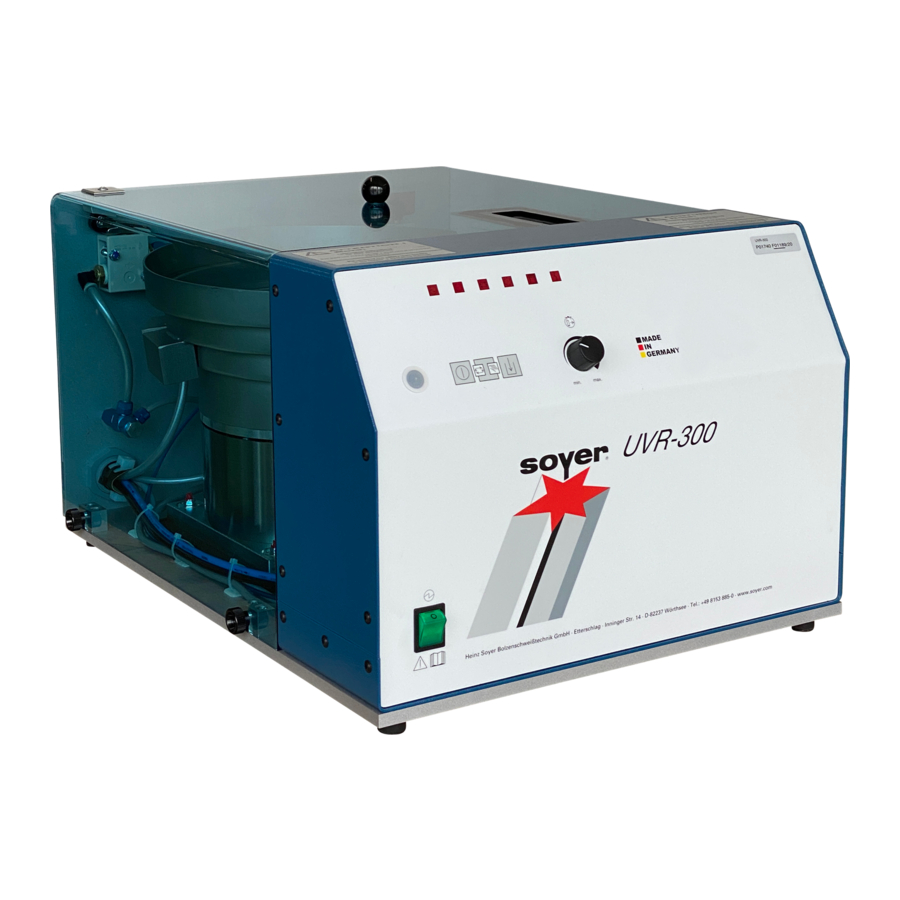
Overview of UVR-300 / UVR-400 feeder Complete overview Figure 1: Overview of UVR-300 feeder (UVR-400 is similar) Item Designation Protective hood Function keys of the universal feeder (see “6.2.1 Overview of the front panel” from page 21) Both sides, locking screws for the protective hood... -
Page 19: Rear Panel/Connections
Blow air regulator Type plate Main air connection Observe the maximum permitted pressure. Hose package with all lines and hoses for connection to the stud welding device and with the mains plug for the feeder. Operating instructions UVR-300/UVR-400 | Heinz Soyer Bolzenschweißtechnik... - Page 20 Transport area Figure 3: Overview of the transport area UVR-300 (UVR-400 is similar) Item Designation Feeder bowl with welding studs Connection piece for the stud feed hose (replaceable part) Outlet rail (replaceable part) Blow-off nozzles to separate studs lying on top of one another...
-
Page 21: Overview Of The Controls
Overview of the controls 6.2.1 Overview of the front panel Figure 4: Overview – Front panel of UVR-300 (UVR-400 is similar) Item Designation Mains switch for turning the mains supply on/off Function key: ON/OFF, to switch the control system on/off Function key: Operating mode to switch to ... -
Page 22: Display Of The Operating States
LED lights up when vibration drive is in operation. Automatic LED lights up with automatic operation being switched on. No function LEDs unassigned with UVR-300 / UVR-400. Malfunction LED lights up in case of malfunction. Operating instructions UVR-300/UVR-400 | Heinz Soyer Bolzenschweißtechnik... -
Page 23: Special Functions (Potentiometer)
The reload time can be regulated based on the stud diameter. Turning to the left increases the time; turning to the right shortens the time. P 2: Frequency adjustment for the feeder vibration drive. Operating instructions UVR-300/UVR-400 | Heinz Soyer Bolzenschweißtechnik... -
Page 24: Technical Data For The Universal Feeder
Technical data for the universal feeder 6.5.1 Technical data for the UVR-300 universal feeder Designation UVR-300 universal feeder Item no. P01740 ® SOYER threaded studs and pins with flange in accordance with DIN EN ISO 13918 Working area M3, M4, M5, M6, Ø 7.1 and M8 from 6 - 40 mm in length... -
Page 25: Technical Data For The Uvr-400 Universal Feeder
Only replace fuses when the mains plug is disconnected! Should it become necessary to replace fuses, only use fuses with the specified electrical values. Oversized fuses could either cause defects in the electrical system or a fire. Operating instructions UVR-300/UVR-400 | Heinz Soyer Bolzenschweißtechnik... -
Page 26: Setup And Connection Of The Devices
(e.g. by grinding work). Danger from humid operation site There is a danger of electrocution when operating the device in a humid environment. The device must only be operated in a dry environment. Operating instructions UVR-300/UVR-400 | Heinz Soyer Bolzenschweißtechnik... -
Page 27: Example For A Connection Diagram
For example, in connection with the energy source BMS-9 Automatic and the PS-3A stud welding gun, the studs can be fed into the gun automatically using compressed air. Figure 7: Example for a connection diagram with UVR-300 (UVR-400 is similar) Item Designation... -
Page 28: Connections On The Universal Feeder
Check that the mains switch is turned off and after installation, connect the feeder to the power supply using the mains plug. You can find the mains plug in the hose package (a). The device is connected. Operating instructions UVR-300/UVR-400 | Heinz Soyer Bolzenschweißtechnik... - Page 29 If the stud feed hose is used incorrectly, or an unsuitable hose is used, there is a risk of injury from ejected welding studs. Only use original stud feed hoses from Soyer GmbH. Only ever use stud feed hoses which match the stud diameter.
- Page 30 Connect the blowing air line (a) from the feeder hose package. Observe the maximum permitted pressure. Observe the labelling on the connection and hose, do not mix up! (B/blow air = silver hose) Operating instructions UVR-300/UVR-400 | Heinz Soyer Bolzenschweißtechnik...
-
Page 31: Permitted Devices In Combination With The Universal Feeder
Hazards for the operator may occur when wrong devices are used. Only use devices permitted by Soyer GmbH. The use of other devices or devices from another manufacturer invalidate the declarations of conformity and warranties of Soyer GmbH. ® Permitted SOYER stud welding guns for automatic operation... - Page 32 Stud welding device Note BMS-9/9V Automatic Capacitor discharge stud welding device BMS-10N/NV Automatic Capacitor discharge stud welding device BMS-10P Capacitor discharge stud welding device BMK-16i Automatic Drawn arc and SRM ® stud welding device Operating instructions UVR-300/UVR-400 | Heinz Soyer Bolzenschweißtechnik...
-
Page 33: Cleaning The Devices
Improper cleaning may cause damage to the device. Make sure that no detergents get into the device. Do not use aggressive detergents for cleaning the device. The frequency of cleaning depends on the operating conditions of the devices. Operating instructions UVR-300/UVR-400 | Heinz Soyer Bolzenschweißtechnik... -
Page 34: Converting The Universal Feeder
The parts to be converted are labelled according to the stud diameter for which they must be installed. 7.1.1 Conversion set for M3 - M8 (preferably for UVR-300) Figure 8: Conversion set with replaceable parts for UVR-300 Item Designation... -
Page 35: Conversion Set For Uvr-400 (M10, M12 And Ø 10.8)
Hose connection Hose locking device All conversion set parts can be ordered separately. Please refer to chapter “12.2 Individual parts for the UVR-400 conversion set (M10, M12 and Ø 10.8)” on page 62. Operating instructions UVR-300/UVR-400 | Heinz Soyer Bolzenschweißtechnik... -
Page 36: Carrying Out The Conversion
Carrying out the conversion The following describes how to convert the UVR-300 universal feeder and the UVR-400 universal feeder to a different stud diameter. To convert the feeders to another stud diameter, proceed as follows: Adjust the step width ... -
Page 37: Adjusting The Step Width
(a). Studs which are parallel to one another or on top of one another (b) will then fall off the plate. After the adjustment, retighten the clamp screws (c). The step width is adjusted. Operating instructions UVR-300/UVR-400 | Heinz Soyer Bolzenschweißtechnik... -
Page 38: Replacing The Connection Piece For The Stud Feed Hose (M3 - M8)
Allen key if required. Step 3: Remove the required hose connection from the conversion set. Each hose connection is labelled with the stud diameter for which it must be used (a). Operating instructions UVR-300/UVR-400 | Heinz Soyer Bolzenschweißtechnik... - Page 39 Ensure that the hose end is clean, straight and free of burrs. Lightly chamfer the internal diameter of the hose, to avoid studs becoming ® stuck (e.g. with the 60° countersink F04922 from SOYER Insert the hose into the connection piece until the stop. The hose connection has been replaced.
-
Page 40: Replacing The Outlet Rail And Rotating The Stud Retainer
To remove and insert the stud retainer, use a screw or a stud with diameter M10 which you screw into the centre (c). Remove the screw/stud again after inserting the barrel. Step 4: Loosen the fastening screws (a). Operating instructions UVR-300/UVR-400 | Heinz Soyer Bolzenschweißtechnik... - Page 41 Insert the outlet rail (a) and the panel with the compressed air connection (b). Fasten both with the tommy screw (c) and the fastening screw (d). Be careful not to damage the compressed air lines and the compressed air nozzles. Operating instructions UVR-300/UVR-400 | Heinz Soyer Bolzenschweißtechnik...
- Page 42 If not, open the tommy screw (b) and push the block on the transition (c) until there is a clean, aligned transition. Step 9: Attach the hold-down plate with the fastening screw (a) above the outlet rail. The outlet rail has been changed. Operating instructions UVR-300/UVR-400 | Heinz Soyer Bolzenschweißtechnik...
-
Page 43: Replacing The Limit Stop Distance Plate
Each limit stop distance plate is labelled with the stud diameter for which it must be used (a). Step 4: Attach the limit stop distance plate (a) and clamp it with the tommy screw (b). The limit stop distance plate has been changed. Operating instructions UVR-300/UVR-400 | Heinz Soyer Bolzenschweißtechnik... -
Page 44: Differing Work Steps For Uvr-400
Step 1: Turn off the mains switch on the device, disconnect the main air supply and remove the cover hood. Step 2: Loosen the fastening screws (a) and remove the cover panel (b). Operating instructions UVR-300/UVR-400 | Heinz Soyer Bolzenschweißtechnik... - Page 45 (b). To pull out and insert the stud retainer, use a screw or a stud with diameter M10 which you screw into the centre (c). Remove the screw/stud again after inserting the barrel. Operating instructions UVR-300/UVR-400 | Heinz Soyer Bolzenschweißtechnik...
- Page 46 Slide the stud retainer (a) to the end position (b) until the stop. Step 6: Use the hose connection required for the stud size used. Each hose connection is labelled with the stud diameter for which it must be used (a). Operating instructions UVR-300/UVR-400 | Heinz Soyer Bolzenschweißtechnik...
- Page 47 Step 8: Attach the cover panel (a) with the fastening screws (b) above the escapement. To do this, push the cover panel (a) in the direction of the hose connection (c) until the stop. Operating instructions UVR-300/UVR-400 | Heinz Soyer Bolzenschweißtechnik...
- Page 48 The hose clip is sufficiently tight when the hose can no longer be moved/turned. Do not overtighten the hose clip to avoid pinches and damage to the hose. The deviating conversion work is finished. Operating instructions UVR-300/UVR-400 | Heinz Soyer Bolzenschweißtechnik...
-
Page 49: Adjusting The Universal Feeder
For this, please also refer to chapter “9.1 Eliminating malfunctions at the universal feeder” on page 57. 7.8.1 Adjusting the blow air regulator Figure 11: Blow air regulator UVR-300 (UVR-400 is similar) Item Designation Manometer Pressure regulator Pull out to make the adjustment, push back in after adjusting the pressure. -
Page 50: Adjusting The Blow-Off Nozzles
7.8.2 Adjusting the blow-off nozzles Figure 12: Blow-off nozzles UVR-300 (UVR-400 is similar) Item Designation Blow-off nozzles Part to be blown off (example) Valve for regulating the blow-off air The blow-off nozzles prevent an incorrectly positioned stud from being transported further. -
Page 51: Adjusting The Transport Speed Of The Weld Studs
The transport speed to be adjusted depends on the type and size of the welding studs. The welding studs must be transported upwards evenly, without gaps and without being pushed on top of one another. Operating instructions UVR-300/UVR-400 | Heinz Soyer Bolzenschweißtechnik... -
Page 52: Readjusting The Limit Switch
To adjust this, the compressed air remains switched off and the mains switch of the device is switched on for power supply. Push the feed slide into the end position of the limit switch to be adjusted. Then, move the limit switch until its LED lights up. Operating instructions UVR-300/UVR-400 | Heinz Soyer Bolzenschweißtechnik... -
Page 53: Preparing The Devices For The Welding Operation
Do not look directly into the flash. The gun carries out lifting movements during the welding process. Do not hold the gun tight in the area of moving parts. Operating instructions UVR-300/UVR-400 | Heinz Soyer Bolzenschweißtechnik... -
Page 54: Starting The Automatic System And Carrying Out Welding
Fill the feeder bowl with welding studs. ® Only use SOYER welding studs. Observe the permitted filling weight. Step 5: Push the continuous load button (a) on the feeder. The studs are transported to the stud retainer. Operating instructions UVR-300/UVR-400 | Heinz Soyer Bolzenschweißtechnik... - Page 55 Hold guns or welding heads with the stud ejectors facing downwards and do not point them at persons or animals. Step 9: Ensure that the welding points on the stud and workpiece are metallically bright. Operating instructions UVR-300/UVR-400 | Heinz Soyer Bolzenschweißtechnik...
-
Page 56: Refilling The Feeder During Operation
Switch off the universal feeder at the mains switch. Switch off the main compressed air or disconnect the device from the compressed-air supply. Switch off any other devices that may be connected to the universal feeder. Operating instructions UVR-300/UVR-400 | Heinz Soyer Bolzenschweißtechnik... -
Page 57: Maintenance And Repair
9 Maintenance and repair Maintenance and repair of the devices may only be performed by Heinz Soyer Bolzenschweißtechnik GmbH or authorised specialists. Eliminating malfunctions at the universal feeder Risk due to accelerated welding studs The welding studs are transported using compressed air and are therefore greatly accelerated. - Page 58 The permitted stud fill quantity has been exceeded. Observe the maximum stud fill quantity, remove studs again if necessary. See chapter "6.5.1 Technical data for the UVR-300 universal feeder" on page 24. The feeder drive is The feeder controls are set to “Manual”. The “Automatic” control LED has running constantly.
-
Page 59: Service
Fax: 0049-8153-8030 Email: info@soyer.de Please have the serial number ready during service requests. ® Alternatively, you can also contact your respective SOYER agent. The contact data is available on our website at www.soyer.de or www.soyer.com (English) 11 Warranty conditions The warranty period for commercial or equivalent use is 12 months. If repair is required, we guarantee the correction of the defects at the Etterschlag plant. -
Page 60: Spare And Wear Parts
(M3 - M8) which need to be changed. The parts to be converted are labelled according to the stud diameter for which they must be installed. Figure 14: Conversion set UVR-300 – exchange parts (1) Individual parts in the feeder conversion set Item... - Page 61 Individual parts in the feeder conversion set Figure 15: Conversion set UVR-300 – exchange parts (2) Individual parts in the feeder conversion set Item Description Dimension Item no. Limit stop for fixing F05335 bracket Lens flange screw M5 x12 mm...
-
Page 62: Individual Parts For The Uvr-400 Conversion Set (M10, M12 And Ø 10.8)
M4 x 8 mm M01563 screw Distance piece F05567 F05568 Ø 10.8 F05747 Hose connection F05230 F05231 Ø 10.8 F06246 SK 16 – 25 mm Hose locking device M01514 (hose clip with screw thread) Operating instructions UVR-300/UVR-400 | Heinz Soyer Bolzenschweißtechnik... - Page 63 Operating instructions UVR-300/UVR-400 | Heinz Soyer Bolzenschweißtechnik...
- Page 64 Heinz Soyer Bolzenschweißtechnik GmbH Inninger Straße 14 82237 Wörthsee Tel.: 0049-8153-885-0 E-Mail: info@soyer.de www.soyer.de...
Need help?
Do you have a question about the UVR-300 and is the answer not in the manual?
Questions and answers