Table of Contents
Advertisement
Safety, Operation & Maintenance Manual
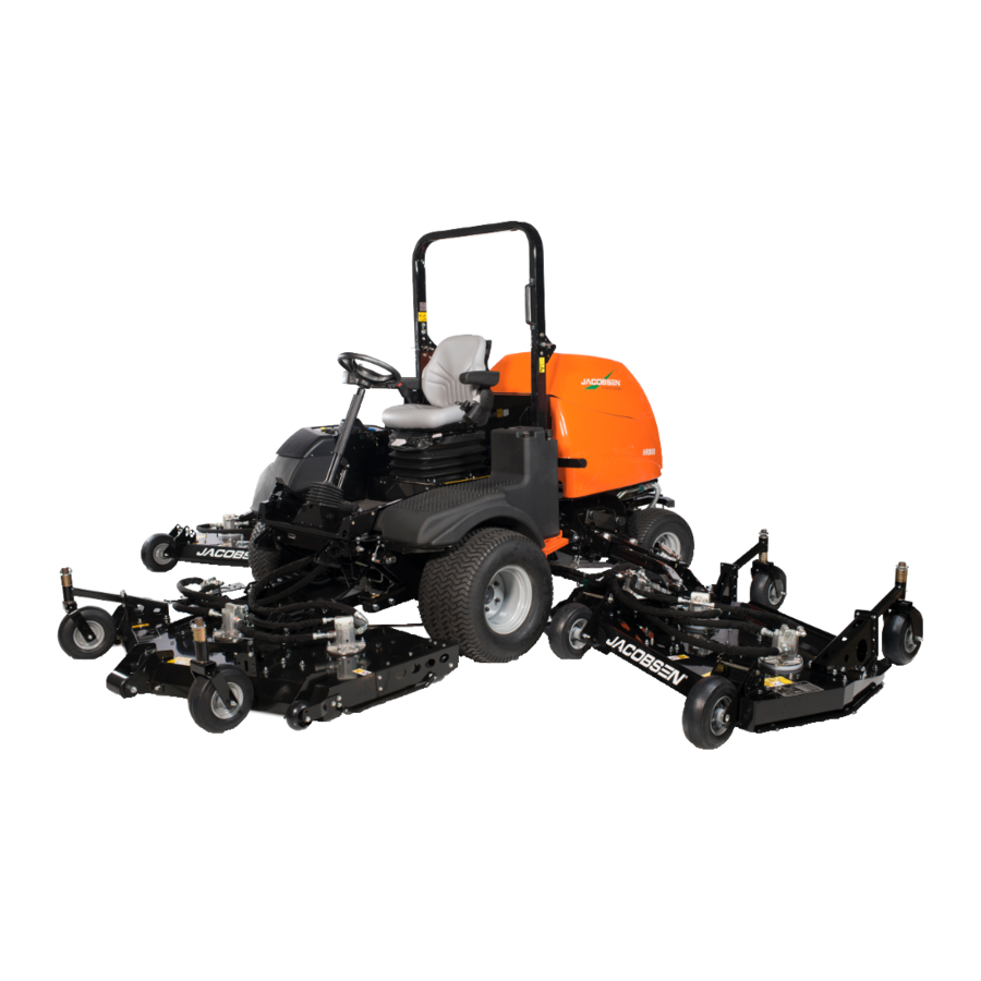
HR800™ Rotary Mower
70543 – HR800, Kubota® V3307-CR-T-E4B
WARNING: If incorrectly used this machine can cause severe injury. Those who use and maintain this machine
must be trained in its proper use, warned of its dangers and must read the entire manual before attempting to
set up, operate, adjust or service the machine.
RJL 100 June 2016
GB
United
Kingdom
WARNING
4372606-GB Rev A
Advertisement
Table of Contents

Subscribe to Our Youtube Channel
Related Manuals for Textron Jacobsen HR800


Summary of Contents for Textron Jacobsen HR800
- Page 1 4372606-GB Rev A Safety, Operation & Maintenance Manual HR800™ Rotary Mower 70543 – HR800, Kubota® V3307-CR-T-E4B WARNING WARNING: If incorrectly used this machine can cause severe injury. Those who use and maintain this machine must be trained in its proper use, warned of its dangers and must read the entire manual before attempting to set up, operate, adjust or service the machine.
-
Page 2: Table Of Contents
8.2 General Precautions ............76 8.3 Engine ................76 8.4 Engine Lubrication ............77 8.5 Engine Coolant ..............78 Proposition 65 Warning © 2016, Jacobsen, A Textron Company/Textron Innovations Inc. This product contains release “All rights reserved, including the right to reproduce this material chemicals known to the State of or portions thereof in any form.”... -
Page 3: Introduction 1
INTRODUCTION 1 IMPORTANT ______________________________________________________________ 1Introduction The HR800 with Diesel engine is a self propelled rotary mower. With hydraulic systems to power the traction drive, the cutting unit lift and lower, the cutting unit drives and the steering. IMPORTANT: Do the maintenance indicated in this manual to make sure that the quality of cut is kept at a high level. This Manual is part of the machine and must stay with the machine always. -
Page 4: Product Identification
1 INTRODUCTION PRODUCT IDENTIFICATION _________________________________________________ Mower Serial number plate ® Mowers without CE Gross weight (Kg) A Textron Company Option Engine Power (Kw) CHARLOTTE, NC PRODUCT OF U.S.A. Date code Product number and Serial number ® 11524 WILMAR BLVD, CHARLOTTE, NC 28273... - Page 5 THIS ROPS MEETS THE REQUIREMENTS OF ISO 21299-2009 For Product IT HAS BEEN DESIGNED TO BE FITTED TO JACOBSEN HR800 SERIES MOWING MACHINES WITH A MAXIMUM VEHICLE Serial Number WEIGHT OF 5000 POUNDS OR 2268 Kg. THIS DECAL MUST BE KEPT...
-
Page 6: Guidelines For The Disposal Of Scrap Products
1 INTRODUCTION GUIDELINES FOR THE DISPOSAL OF SCRAP PRODUCTS _______________________ 1.3.1 DURING SERVICE LIFE_____________________________________________________ All the used fluids and parts must be controlled as hazardous materials material. Recommended procedures must be followed for their safe removal. If a fluid leak occurs, contain the spill to make sure that the leak does not flow into the ground or drainage system. Follow the regulations in force to make sure that leaks are controlled. - Page 7 INTRODUCTION 1 PARTS MANUAL __________________________________________________________ To refer to the parts list for this mower you have four options: Website – www.jacobsen.com. Select the “ONLINE PARTS LOOK-UP” tab. These pages will show the parts list and the line drawings you need to help with the identification of spare parts. Website –...
-
Page 8: Safety
2 SAFETY HOW TO OPERATE SAFELY _______________________________________________________ 2Safety WARNING EQUIPMENT OPERATED INCORRECTLY OR WITHOUT TRAINING CAN BE DANGEROUS. Know the location and correct operation of controls. Operators without experience must receive instruction from another person that knows the correct operation of the equipment before you operate the mower. Only use parts, accessories and attachments approved by Jacobsen. - Page 9 SAFETY 2 Inspect the cutting system before you start the mower. Make sure the blades are free to rotate. When you rotate one blade, other blades can rotate. 2.1.3 OPERATION Never operate the engine without enough ventilation or in an enclosed area. The carbon monoxide in the exhaust fumes can increase to dangerous levels.
- Page 10 2 SAFETY 2.1.4 ROPS The ROPS is a safety device. Keep the ROPS in the vertical and locked position. Always use the seat belt when you operate the mower. Make sure the seat belt can be released quickly in an emergency. Only operate the mower with the ROPS in the folded position on flat and level surfaces when necessary.
- Page 11 SAFETY 2 Disconnect the battery before you service the mower. Always disconnect the negative battery cable before the positive battery cable. Always connect the positive battery cable before the negative battery cable. Charge the battery in an area with good airflow. The battery can release hydrogen gas that is explosive. To prevent an explosion, keep any device that can cause sparks or flames away from the battery.
- Page 12 2 SAFETY 2.1.8 IMPORTANT SAFETY NOTES________________________________________________ This safety alert symbol gives a warning of possible hazards. DANGER - Indicates a dangerous condition that WILL cause death or injury unless it is prevented. WARNING - Indicates a dangerous condition that CAN cause death or injury unless it is prevented. CAUTION - Indicates a dangerous condition that can cause injury and property damage unless it is prevented.
- Page 13 SAFETY 2 WARNING California Proposition 65 Engine exhaust, some of its constituents, and some vehicle components contain or release chemicals known to the state of California to cause cancer and birth defects or other reproductive harm. WARNING To prevent injury from the hot oil at high pressure, do not use your hands to check for oil leaks. make sure that you use paper or cardboard.
- Page 14 2 SAFETY WARNING Vibration Exposure Limits Exposure limits are calculated as a combination of the vibration level (magnitude) of the tool and the Daily Exposure Time (Trigger Time). E.g. A product with 5m/s² vibration can be used up to 2 hours/day to reach the EAV and up to 8 hours/day to reach the ELV.
-
Page 15: Decals 3
DECALS 3 SAFETY DECALS __________________________________________________________ 3Decals 4324674 4170640 4153197 18°+ 4321506 en-14... - Page 16 3 DECALS 009034920 Caution, Stay Away From Hot Surfaces. 009034880 Caution, fan blade, do not open or remove the safety shields while the engine is in operation. 009034900 Caution, drive belt, do not remove the safety shields while the engine is in operation. 4324674 Caution, Low Sulfur Diesel Fuel.
-
Page 17: Instruction Decals
DECALS 3 INSTRUCTION DECALS TOTAL EQUIVIS ZS 46 CLASSIFICATION CJ-4 1-2-3 1-2-3 25 MM 1.0 IN 25 MM 1.0 IN 28 MM 1.5 IN 28 MM 1.5 IN 50 MM 2.0 IN 50 MM 2.0 IN 63 MM 2.5 IN 63 MM 2.5 IN 76 MM... - Page 18 3 DECALS Description 009034770 Guaranteed Sound Power Level 4286422 Hydraulic Fluid 009039870 Jack & Hook Point 164580 Lubrication Point 4316686 Engine Oil Classification 4355986 Height Of Cut - Wing deck 4359126 Height Of Cut - Front Deck en-17...
-
Page 19: Controls 4
CONTROLS 4 OPERATOR COMPARTMENT ________________________________________________ 4Controls en-18... -
Page 20: Control Panel
4 CONTROLS CONTROL PANEL _________________________________________________________ 5.2.18 5.2.17 Mowers with Cab 5.2.19 5.2.16 5.2.14 5.2.21 5.2.15 5.2.2 5.2.13 5.2.20 5.2.7 5.2.4 5.2.5 5.2.11 5.2.12 Mowers with 2 Post ROPS 5.2.4 5.2.7 5.2.5 5.2.8 5.2.23 5.2.22 5.2.2 5.2.11 5.2.12 5.2.6 5.2.22 5.2.9 5.2.21 5.2.10 5.2.23... - Page 21 CONTROLS 4 4.2.1 STARTER KEY SWITCH_____________________________________________________ Turn the starter key to the right to the 'start' position to start the engine. When the engine starts, release the key and allow to return automatically to the 'on' position to run. NOTE. There can be a time delay before the engine starts, it depends on the engine temperature while the glow plugs operate automatically.
- Page 22 4 CONTROLS 4.2.5 MOW SWITCH ____________________________________________________________ The mow switch engages mow speed and cutter rotation. To cut grass, push the front of the switch and move the joysticks forward to lower the decks. When engaged the yellow LED on the pod is illuminated. To stop the blade, push the rear of the rocker switch.
- Page 23 CONTROLS 4 4.2.8 DPF SWITCH _____________________________________________________________ With the switch in the center position (default) it allows automatic Active Regen. Operation of the mower is not changed during Active Regen. See 8.15 When the Regen Request light flashes, press and release the front part of the switch to start the Parked Regen cycle.
- Page 24 4 CONTROLS 4.2.12 ROTATING BEACON ______________________________________________________ Operates the vehicles rotating beacon when a cab is not fitted. 4.2.13,14,15 LIFT/LOWER SWITCHES______________________________________________ 5.2.13. Right Hand Wing Cutter Deck 5.2.15 5.2.14 5.2.14 Front Cutter Deck 5.2.13 5.2.15 Left Hand Wing Cutter Deck To lower the cutting unit move the switch lever forward. To raise the cutting unit move the switch lever rearwards NOTE: If the cutter switch is engaged when the unit is lowered the green lamp will illuminate...
- Page 25 CONTROLS 4 4.2.20 WEIGHT TRANSFER BUTTON ______________________________________________ The button will transfer weight by the hydraulic system between the drive wheels and the cutter deck. To adjust the amount of weight transfer manually on the lift valve. See section 7.2. 4.2.21 HORN___________________________________________________________________ The horn button is on the control panel.
- Page 26 4 CONTROLS 4.2.23.2 WARNING / SERVICE SCREEN ____________________________________________ After the startup screen the warning screen is shown, the screen is visible for four seconds. If the machine is within 5 hours of the next service, a warning is shown. An operator input is needed to continue to the main screen.
- Page 27 CONTROLS 4 4.2.23.3 FIRST SCREEN _________________________________________________________ This screen shows the cutter switch in the OFF position, the transport lock engaged, the TST is in operation and speed mode set to creep. the MODE button the transmission mode can be changed By pressing between Automatic, Manual and Creep.
- Page 28 4 CONTROLS 4.2.23.5 THE ENGINE WILL NOT START____________________________________________ When the ignition key is turned to the start position this screen is shown. If any of the following flash. • The parking brake is not applied. • The cutter switch is not in the OFF position. •...
- Page 29 CONTROLS 4 4.2.23.8 TIME DISPLAY OPTION___________________________________________________ This display this displays the time and engine hours. This display shows the date and engine hours. Button 2 toggles between the two options. MODE 4.2.23.9 MAIN MENU SELECT ____________________________________________________ Use the button below the to access the main menu.
- Page 30 4 CONTROLS 4.2.23.11 DATE SELECT _________________________________________________________ Press the button and the day is underlined. Press the button up and down to move the count. C l o c k S e t t i n g s Press the button to accept and move to the month (underlined).
- Page 31 CONTROLS 4 SERVICE MENU Please note some functions require a PIN to access. 4.2.23.14 SERVICE MENU ________________________________________________________ button accepts the option that has the is moved with the up and down to select, fault log, time until service, diagnostics, I/O diagnostics and ECU (engine Control Unit) monitor.
- Page 32 4 CONTROLS 4.2.23.17 FAULT LOG DETAIL ____________________________________________________ Select the fault log to be accessed and accept to show the details. These details show the date and time of the fault. F a u l t l o g Press the button to return to previous menu.
- Page 33 CONTROLS 4 4.2.23.20 DIAGNOSTICS _________________________________________________________ Water Temp [deg C] = 60.5 Fuel Level [pct] = 100 D i a g n o s t i c s Sys Voltage [V] = 11.8 Wa t e r Te m p [ d e g C ] = 6 0 . 5 F u e l L e v e l [ p c t ] = 1 0 0 Cutter [h] = S y s Vo l t a g e [ V ] = 11 .
- Page 34 4 CONTROLS 4.2.23.23 CONNECTOR J2 _______________________________________________________ This screen shows the status of the J2 connectors. Press the left side button to return to I/O diagnostics menu. Connector J2 On and OFF shown for illustration purposes only. J2-1 Right Lower J2-2 Right Lift J2-3 Center Lift J2-4 High Speed Sol J2-5 Left Lower...
- Page 35 CONTROLS 4 4.2.23.26 CONNECTOR J5 _______________________________________________________ This screen shows the status of the J5 connectors. Press the left side button to return to I/O diagnostics menu. Connector J5 On and OFF shown for illustration purposes only. J5-1 Center Deck LED Output J5-2 Left Mow Solenoid J5-3 Deck Lock Solenoid (3,4) J5-4 Center Mow Solenoid...
- Page 36 4 CONTROLS 4.2.23.29 SERVICE MANAGER PIN INPUT __________________________________________ Press the button up and down to change the numbers. Select . to accept. Insert PIN Initial PIN number is 1001 0 0 0 0 Note. Service managers are advise to change the pin to stop the machine parameters being changed to an dangerous condition.
- Page 37 CONTROLS 4 4.2.23.32 INFORMATION SCREEN TWO ____________________________________________ This screen displays, engine-total fuel used (liter) engine fuel rate (l/h). Press the button up and down to move between screen one and two. Engine Total Fuel used Engine Fuel Rate litre Drive Engine Torque DSF Soot SETTINGS MENU Please note some functions require a PIN to access.
- Page 38 4 CONTROLS 4.2.23.35 MEASURE UNITS MENU ________________________________________________ Select the measure units and accept S e t t i n g s M e n u M o d e M e a s u r e U n i t s P I N 4.2.23.36 MEASURE UNITS ______________________________________________________ ...
- Page 39 CONTROLS 4 4.2.23.37 PIN MENU_____________________________________________________________ Select the PIN menu and accept S e t t i n g s M e n u M o d e M e a s u r e U n i t s P I N 4.2.23.38 INPUT PIN_____________________________________________________________ Press the button...
- Page 40 4 CONTROLS 4.2.23.40 CRUISE SELECT _______________________________________________________ Select between “mow mode, not enabled”, “mow and transport mode” or “transport mode” use button up and down to move between them. Press the button .to accept C r u i s e M e n u M o w M o d e Press the button to return to previous menu.
- Page 41 CONTROLS 4 4.2.23.43 VEHICLE SPEED _______________________________________________________ Select the vehicle speed and accept P i n M e n u C r u i s e C o n t r o l C r o s s C u t Ve h i c l e S p e e d Change PIN Inclinometer...
- Page 42 4 CONTROLS 4.2.23.46 INCLINOMETER _______________________________________________________ Select to shows TST status, Enabled or Disabled. Press the button up and down to move P i n M e n u TST Setting between Enabled or Disabled Select . To C r u i s e C o n t r o l TST Status Not Fitted accept.
- Page 43 CONTROLS 4 4.2.23.49 FAN DRIVE ____________________________________________________________ Select the Fan Drive and accept The normal fan operation is based on engine temperature. Fan speed will increase as P i n M e n u F a n D r i v e M e n u engine temperature increases.
- Page 44 4 CONTROLS 4.2.23.51 LANGUAGE MENU _____________________________________________________ Select the language and accept On the page for the language options, Press the button to select, press the button L a n g u a g e M a i n M e n u ...
- Page 45 CONTROLS 4 4.2.23.54 WARNING SLOPE ANGLE 21° ____________________________________________ If the slope angle reaches 21° the screen will display this warning indicating that at 21° the front cutter deck will be lifted and held above the ground to improve the stability and all cutting units will stop rotation. An audible warning will be given, the buzzer will sound four times every 4 seconds and the red LED’s will flash four times every 4 seconds.
- Page 46 4 CONTROLS 4.2.23.57 WARNING ENGINE FAULT _______________________________________________ When this screen is shown, there is an engine fault.Stop the engine as soon as possible and contact your service dealer. When this fault occurs the machine go’s into limp-home mode. Press the button below the to confirm the fault.
- Page 47 CONTROLS 4 4.2.23.60 WARNING CHARGE FILTER BLOCKED ____________________________________ When this screen is shown, the hydraulic-charge filter is blocked and needs replacing. Replace the filter element at the earliest opportunity to avoid possible hydraulic system damage. Press the button below the to confirm the fault.
- Page 48 4 CONTROLS 4.2.23.63 WARNING SOLENOID FAULT ____________________________________________ When this screen is shown, there is a hydraulic circuit solenoid fault. Go to i/o diagnostics for solenoid identification. Press the button below the to confirm the fault. FAULT SOLENOID 4.2.23.64 WARNING (TST) TILT SENSOR TECHNOLOGY FAULT ________________________ When this screen is shown, there is a fault with the TST.
-
Page 49: Traction Pedal
CONTROLS 4 TRACTION PEDAL _________________________________________________________ The traction pedal is found on the right side of the footplate. • Carefully press the top (A) of the foot pedal to reach the forward speed that you need. • To stop - Carefully return the foot pedal to the Neutral position. •... -
Page 50: Seat Right-Side Armrest And Pod
4 CONTROLS SEAT RIGHT-SIDE ARMREST AND POD _______________________________________ The right-side armrest of the seat carries the control pod. The Control Pod position is adjustable, as shown, to give a good position for the operation of the controls. Release the hand wheel (A). To lift or lower the armrest, use two hands. -
Page 51: Tow Valve
CONTROLS 4 TOW VALVE ______________________________________________________________ The Tow valve is situated on the right hand side of the transmission pump. To push the machine, disengage the parking brake, see section 5.8 Turn screw (A) located on the right side of the transmission pump three complete turns counterclockwise. -
Page 52: Cab Controls
4 CONTROLS CAB CONTROLS __________________________________________________________ Left Turn Signal Working Lights Switch (Optional) Beacon Switch Front Screen De-Frost / De-Mist Switch Rear Screen Wiper Switch (Optional) Front Screen Wash Switch Front Screen Wiper Switch Right Turn Signal Fan Control Air Conditioning Control Temperature Control Fuse Holder Fuse Holder... -
Page 53: Operation 5
OPERATION 5 DAILY INSPECTION ________________________________________________________ 5Operation CAUTION The inspection must be done each day when the engine is turned off and all fluids are cold. Lower the cutting units to the ground, engage the parking brake, stop the engine and remove the ignition key. Do a visual inspection of the mower. -
Page 54: Interlock System
5 OPERATION INTERLOCK SYSTEM ______________________________________________________ The Interlock System prevents the engine to start unless the operator is in the seat, the parking brake is engaged and the mow switch is in the OFF position. The system stops the engine if the operator leaves the seat with the mow switch in the ON position or the parking brake disengaged. -
Page 55: Operating Procedure
OPERATION 5 OPERATING PROCEDURE __________________________________________________ WARNING This mower has a Roll Over Protection Structure (ROPS). Always wear the seat belt. If the mower is over turning, hold the steering wheel. Do not try to move off the mower or leave the seat. CAUTION To prevent injury, always wear safety glasses, leather work shoes or boots, a hard hat and ear protection. -
Page 56: Starting The Engine
5 OPERATION STARTING THE ENGINE ____________________________________________________ Start the engine with the operator in the seat, the mow switch (A) in the OFF position and the parking brake switch (B) in the ON position. Remove your foot from the traction pedal. Always wear the seat belt. Set the throttle control (C) to half throttle. -
Page 57: Driving
OPERATION 5 DRIVING _________________________________________________________________ Read and follow all safety instructions contained in this manual when you drive the mower. When you operate in the reverse direction, look behind you to make sure you have a clear path. IMPORTANT: Equipment must meet the current regulations to be driven on the public roads. To transport the mower, move the mow switch to the OFF position, lift the cutting units to the transport position and move the transport lock switch to the ON position. -
Page 58: To Remove A Blockage From Cutting Units
5 OPERATION TO REMOVE A BLOCKAGE FROM CUTTING UNITS _____________________________ Stop and lift the cutter decks before you move the machine to level ground. Engage the transport locks. Turn off the engine and remove the ignition key. If the front cutter deck has become blocked, you will need to tilt front cutter deck refer to section 8.19 Wear the personal protective equipment that is applicable for this work, for example eye protection, gloves and correct footwear. -
Page 59: Mowing On Slopes
OPERATION 5 MOWING ON SLOPES ______________________________________________________ The mower is designed for good traction and stability in normal conditions for operation. On wet grass slopes use caution, as wet grass decreases traction and steering control. WARNING To decrease the possible cause of overturning. The safest method for operation on slopes and terraces is. - Page 60 5 OPERATION Degrees WARNING Grade When the machine is being used, whether cutting grass or not, on slopes, the ROPS frame must be deployed and the seat belt used. This rationale is based on the fact that a seat belt must be worn with a ROPS to comply with the Machinery Directive 2006/42/EC Sections 3.2.2, Seating &...
- Page 61 OPERATION 5 Height (C) Result (D) Inches with 1 Yard Level (A) Millimeters with 1 Meter Level (A) Slope in Degrees Slope Grade % 10.0 16.7 11.3 20.0 11.8 20.8 12.7 22.5 25.0 15.4 27.5 15.5 27.8 16.7 30.0 17.0 30.6 18.0 32.5...
-
Page 62: Towing The Mower
5 OPERATION 6.10 TOWING THE MOWER _____________________________________________________ The machine is fitted with tie-down loops front and rear. Always tie down the machine securely to the trailer. Always follow any recommendations for maximum trailer weights given in your towing vehicles handbook. IMPORTANT Use the chart in the specification section 12.2 to calculate the total weight of your machine configuration. -
Page 63: Adjustments 7
ADJUSTMENTS 7 GENERAL PRECAUTIONS ________________________________________________________ 7Adjustments WARNING Before you clean, adjust or repair this equipment, move the mow switch to the OFF position, lower front and rear cutting units to the ground, turn on the parking brake switch, stop the engine and remove the key. Make sure the mower is parked on a solid and level surface. -
Page 64: Weight Transfer Adjustment
7 ADJUSTMENTS WEIGHT TRANSFER ADJUSTMENT __________________________________________ The weight transfer bias can be adjusted on the lift valve. The valve is accessible by removing the access panel in the operator platform. The valve is situated on the right hand side. To adjust: Loosen the locknut A whilst holding the threaded shaft still with the Allen Key B. -
Page 65: Height Of Cut Adjustment
ADJUSTMENTS 7 HEIGHT OF CUT ADJUSTMENT ______________________________________________ The cutting height is determined by the position of the blades in relation to the caster wheels. Changes to this height are made at all points and can be made in any order. Make adjustment selections for each deck from the height of cut chart for that deck included in this section. -
Page 66: Height Of Cut Adjustment (Wing Cutter Deck)
7 ADJUSTMENTS HEIGHT OF CUT ADJUSTMENT (WING CUTTER DECK)__________________________ Raise the deck to mid position. Engage transport lock Remove the quick pin (A) from the top of the caster wheel pivot spindle Remove the caster wheel from caster support (B). Select either Position 1 or Position 2 for wheel mounting bracket (C). -
Page 67: General Instructions For Grammer Seats
ADJUSTMENTS 7 GENERAL INSTRUCTIONS FOR GRAMMER SEATS _____________________________ All The seat adjustments are to be done while the vehicle is stopped. • After removal of the backrest cover, hold the backrest frame in position with a support before the backrest adjuster is operated. -
Page 68: Air Suspension Seat (Grammer Msg95 -721)
7 ADJUSTMENTS 7.10 AIR SUSPENSION SEAT (GRAMMER MSG95 -721) ______________________________ 7.10.1 WEIGHT ADJUSTMENT____________________________________________________ The seat should be adjusted for the driver's weight with the driver sitting on the seat. The adjustment is made by pulling out or pushing in the actuator lever (1) until the green marking is visible in the weight-and-height indicator (2). - Page 69 ADJUSTMENTS 7 7.10.5 ARMRESTS ADJUSTMENT (OPTION) ________________________________________ The inclination of the armrests can be modified by turning the adjustment knob (arrow). 7.10.6 ARMREST (OPTION) ______________________________________________________ The armrests can be folded up if required and the height individually adjusted. To adjust the armrests for height, separate the round cap (see arrow) from the cover, loosen the hexagon nut (size 13mm) and adjust the armrest to the desired position and tighten the nut again.
- Page 70 7 ADJUSTMENTS 7.10.9 BACKREST ADJUSTMENT (OPTION) ________________________________________ The backrest is adjusted using the locking lever (arrow). • The locking lever must latch into the desired position. It should not be possible to move the backrest into another position when it is locked. 7.10.10 FORE / AFT ISOLATOR (OPTION) __________________________________________ Under certain driving conditions (for example with a trailer attached), it is useful to activate the fore/aft isolator.
- Page 71 ADJUSTMENTS 7 7.10.13 ABSORBER (OPTION) ____________________________________________________ The absorber setting of the seat can be varied to suit the on and off-road driving conditions. The cushioning effect can be individually adjusted for this purpose. Turn the lever to the desired position and release soft hard 7.10.14 MAINTENANCE__________________________________________________________...
-
Page 72: Torque Specification
7 ADJUSTMENTS 7.11 TORQUE SPECIFICATION __________________________________________________ NOTICE The torque values included in these charts are approximate and are for reference only. Use these torque values at your risk. Jacobsen is not responsible for any loss, claim or damage caused by these charts. Always use caution with torque values. -
Page 73: Maintenance And Lubrication 8
MAINTENANCE AND LUBRICATION 8 MAINTENANCE AND LUBRICATION CHARTS __________________________________ 8Maintenance and Lubrication Machine Service Interval Chart Interval Item Section First 50 hours Change the Hydraulic Filter Elements Each day Check Safety Interlock System 10 hours Check the Hydraulic Fluid Level 8.17 ... - Page 74 8 MAINTENANCE AND LUBRICATION en-73...
- Page 75 MAINTENANCE AND LUBRICATION 8 Engine Service Interval Chart Interval Item Section Daily Check Engine Oil Level. 10 hours Check Fuel Level. Check Coolant Level. Check Fan Belt Tension. Check Fuel Pipes and Clamps. Every 50 hours ...
- Page 76 8 MAINTENANCE AND LUBRICATION Interval Item Section Replace Oil Separator Related Rubber Piping. Replace DPF Related Rubber Piping. Replace Intake Air Line and Suction Air Pressure takeout Rubber Piping. Replace Boost Sensor Pressure Rubber Piping. Replace EGR Cooler Rubber Piping.
-
Page 77: General Precautions
MAINTENANCE AND LUBRICATION 8 GENERAL PRECAUTIONS ________________________________________________________ WARNING Before you clean, adjust or repair this equipment, push PTO switch to the OFF position, lower front and wing cutter Decks to the ground, turn on the parking brake switch, stop the engine and remove the key. Make sure the mower is parked on a solid and level surface. -
Page 78: Engine Lubrication
8 MAINTENANCE AND LUBRICATION ENGINE LUBRICATION _____________________________________________________ Check Engine Oil Level Check the engine oil level before you start or at least five minutes after you stop the engine. Park the machine on level ground, remove the dipstick (A), clean with a cloth and replace in position. -
Page 79: Engine Coolant
MAINTENANCE AND LUBRICATION 8 ENGINE COOLANT ________________________________________________________ WARNING To prevent injury from the hot-engine coolant or steam, never remove the radiator cap with the engine in operation. Stop the engine and wait until the radiator is cool. When radiator is cool, use caution to remove the radiator cap. - Page 80 8 MAINTENANCE AND LUBRICATION Check The Engine Coolant Level The level of coolant in a cold expansion tank must be between the indicators. If you need to fill the tank, remove the plastic cap and fill with the correct anti-freeze mixture (See Section 8.1). Replace the plastic cap.
-
Page 81: Hydraulic System
MAINTENANCE AND LUBRICATION 8 HYDRAULIC SYSTEM ______________________________________________________ Drain and replace the hydraulic oil if one of the following occur. • Component failure • Water or foam is in the hydraulic fluid • The hydraulic fluid has a rancid odor (indication of high heat) •... -
Page 82: Hydraulic Filter
8 MAINTENANCE AND LUBRICATION HYDRAULIC FILTER _______________________________________________________ The hydraulic system is protected by two 10 micron filters. Flow through the filter is monitored while you operate the mower. When the difference in hydraulic pressure across the filter is greater than 16 to 20 psi (1.1 to 1.4 BAR), the hydraulic oil filter warning light on the combination gauge will illuminate. -
Page 83: Hydraulic Test Ports
MAINTENANCE AND LUBRICATION 8 HYDRAULIC TEST PORTS __________________________________________________ If you have any problems with the hydraulic system, check the hydraulic pressures with the service ports that are supplied. All tests must be done with the hydraulic oil at the normal temperature of the engine, unless specified at a different temperature. -
Page 84: Fuel
8 MAINTENANCE AND LUBRICATION FUEL____________________________________________________________________ Diesel fuel is flammable. Use caution when you add the fuel to the mower. Only use an approved container. The spout on the container must fit inside the fuel filler neck. Never use the containers that are not approved to keep or transfer fuel. -
Page 85: Fuel System
MAINTENANCE AND LUBRICATION 8 8.10 FUEL SYSTEM ____________________________________________________________ Use Diesel to B.S. EN590 or ASTM D975 (Ultra Low Sulfur) Water Separator If the water is not removed from the fuel, damage to the fuel-injection system can occur. When the fuel filter light on the filter light module is illuminated or at service interval, drain the water from the water separator. -
Page 86: Air Cleaner
8 MAINTENANCE AND LUBRICATION 8.11 AIR CLEANER ____________________________________________________________ Check the service indicator (1) each day. If the red band become visible in the window (2), replace the filter elements. Do not remove the elements to inspect or clean. Removal of the filter that is not necessary increases the risk of dust and other particles to enter the engine. -
Page 87: Battery
MAINTENANCE AND LUBRICATION 8 8.12 BATTERY ________________________________________________________________ Before you service the battery, make sure the ignition switch is in the OFF position and the key is removed. CAUTION When you service the battery, always use the tools with insulation, wear protective glasses and protective clothing. -
Page 88: Charge The Battery
8 MAINTENANCE AND LUBRICATION 8.13 CHARGE THE BATTERY __________________________________________________________ WARNING Charge the battery in an area with good airflow. The battery can release hydrogen gas that is explosive. To prevent an explosion, keep any device that can cause sparks or flames away from the battery. When the battery charger is turned on, to prevent injury, stay away from the battery. -
Page 89: Diesel Particulate Filter
MAINTENANCE AND LUBRICATION 8 8.15 DIESEL PARTICULATE FILTER_______________________________________________ During the operation of the mower, the level of particle material will increase in the Diesel Particulate Filter (DPF) system. The periodic Regen of the DPF system is needed to remove particle material. During an Active or Parked Regen, the engine will use more fuel. -
Page 90: Hydraulic Hoses
8 MAINTENANCE AND LUBRICATION 8.16 HYDRAULIC HOSES ______________________________________________________________ WARNING To prevent injury from the hot, high pressure oil, never use your hands to check for oil leaks. Use the paper or cardboard to find leaks. The hydraulic fluid pressure can have enough force to enter your skin. If hydraulic fluid has entered your skin, a doctor must remove the hydraulic fluid surgically within a few hours or gangrene can occur. -
Page 91: Tires
MAINTENANCE AND LUBRICATION 8 8.17 TIRES ___________________________________________________________________ Keep the tires correctly inflated to increase tire life. Inspect the tread wear. Check the tire pressure each day, while the tires are cool. Use an accurate low-pressure tire gauge. Keep tires inflated at the correct pressure (See Section 8.1) CAUTION DO NOT try to put a tire on a rim unless you have the correct training, tools and experience. -
Page 92: Blade Change
8 MAINTENANCE AND LUBRICATION 8.19 BLADE CHANGE __________________________________________________________ Front Cutter Deck Raise the deck to the cross cut position. This will allow the setting pin D to lift clear of the arm and be easier to remove. Remove the pins at position D on both sides of the machine which lock the deck in its working position. -
Page 93: Inspecting Blades
MAINTENANCE AND LUBRICATION 8 8.20 INSPECTING BLADES ______________________________________________________ Inspected the blade in accordance with the maintenance chart or when the cutting unit is removed from the mower, carefully inspect the blades to make sure the blades are in good condition (A). Replace any blade that has bends (B), grooves (C) or cracks (D). CAUTION Be careful when you check blades to prevent pinching hands and fingers between ends of the blades. -
Page 94: Folding Rops
8 MAINTENANCE AND LUBRICATION 8.22 FOLDING ROPS ___________________________________________________________ A folding Roll Over Protective Structure (ROPS) is included with this mower. Inspect the ROPS weekly for loose hardware or damage. CAUTION Keep the ROPS hardware correctly fastened. Do not do any welding operations, Do not drill, change or bend the ROPS. -
Page 95: Care And Cleaning
MAINTENANCE AND LUBRICATION 8 8.23 CARE AND CLEANING _____________________________________________________ Clean the mower and cutting units after each use. To prevent damage to the engine, do not wash the mower with the engine in operation. When possible, clean the mower with compressed air. NOTICE Do not wash any part of the mower that is hot. -
Page 96: Mower Storage
8 MAINTENANCE AND LUBRICATION 8.24 MOWER STORAGE ________________________________________________________ General • Clean the mower and lubricate. Repair and paint damaged or open metal. • Inspect the mower, tighten all hardware, replace worn or damaged components. • Drain and fill the radiator. •... -
Page 97: Lubrication Of Cutting Unit
MAINTENANCE AND LUBRICATION 8 8.25 LUBRICATION OF CUTTING UNIT ___________________________________________ Wing Pivot Arm (A) Front Pivot Arm (B) Caster Wheel Mounting Pivot (C) en-96... -
Page 98: Problem Solving
9 PROBLEM SOLVING ENGINE PROBLEM SOLVING________________________________________________ 9Problem Solving The Engine is difficult to start Cause Action Check the fuel tank and fuel filter. The fuel is thick and does not flow. Remove any contamination from the fuel system. Clean the fuel filter with kerosene. The fuel system is a pressure type. - Page 99 PROBLEM SOLVING 9 Dirty Smoke or carbon increase on the Exhaust Cause Action Wrong fuel Only use Diesel fuel specified in specification section. Bad Nozzle If necessary, replace the nozzle. Engine must be stopped immediately Cause Action The color of The exhaust turns dark. Check the fuel system and the fuel injection nozzle.
-
Page 100: Quality Of Cut
10 QUALITY OF CUT 10.1 QUALITY OF CUT PROBLEM SOLVING _______________________________________ 10Quality of Cut Make a “test cut” to check the performance of the mower before you start the repairs. This area must have turf conditions that are known and do not change across the area. This type of area allows an accurate inspection of the performance of the mower to be made. -
Page 101: Step Cutting
QUALITY OF CUT 10 10.3 STEP CUTTING____________________________________________________________ Step cutting occurs when grass is cut higher on one side of a cutting unit than the other side. Step cutting can occur when one cutting unit is higher than another cutting unit. The wear of mechanical parts or an incorrect roller adjustment can cause step cutting. -
Page 102: Scalping
10 QUALITY OF CUT 10.4 SCALPING _______________________________________________________________ Scalping is a condition in which areas of grass are cut shorter than the adjacent areas. The area can be light green or brown. A low HOC setting or turf that is not level can cause scalping. -
Page 103: Stragglers
QUALITY OF CUT 10 10.5 STRAGGLERS ____________________________________________________________ Stragglers are separated blades of grass the are not cut, or are cut incorrectly. TN0223 NOTE: Arrow indicates direction of travel. Probable Cause Remedy Edge of the cutting blade(s) are not sharp. Sharpen the blade(s). See Section 8.21 Cut (ground) speed is higher than normal Reduce the cut (ground) speed. -
Page 104: Streaks
10 QUALITY OF CUT 10.6 STREAKS ________________________________________________________________ A streak is a line of grass that is not cut. The cause of a streak can be a damaged blade. TN0224 NOTE: Arrow indicates direction of travel. Probable Cause Remedy Damaged blade(s). Replace the blade(s). -
Page 105: Windrowing
QUALITY OF CUT 10 10.7 WINDROWING ____________________________________________________________ Windrowing is the deposit of clippings increased at one end of cutting unit(s) or between cutting units. Windrowing can make a line in the direction of travel. TN0225 NOTE: Arrow indicates direction of travel. Probable Cause Remedy The grass is higher than the level at which the mower... -
Page 106: Mismatched Cutting Units
10 QUALITY OF CUT 10.8 MISMATCHED CUTTING UNITS ______________________________________________ Mismatched cutting units is a pattern of different cutting heights, that gives the grass a stepped cut appearance. This appearance is normally because of a mismatched HOC (height-of-cut) adjustment from one cutting unit to another unit. -
Page 107: Fuses Relays And Controller 11
FUSES RELAYS AND CONTROLLER 11 11.1 FUSE AND RELAY/COMPONENT IDENTIFICATION ______________________________ 11Fuses Relays and Controller en-106... - Page 108 11 FUSES RELAYS AND CONTROLLER FUSES FUSE HOLDER 1 Fuse Rating Protected Circuits Key Switch to Beacon And Horn Key Switch to Proximity Switches and Pressure Switches Key Switch to Accessory Sockets Key Switch to Machine Control Unit Key Switch to Air Seat Key Switch to Mow Switch FUSE HOLDER 2 Fuse...
-
Page 109: Specifications 12
SPECIFICATIONS 12 12.1 ENGINE SPECIFICATION____________________________________________________ 12Specifications Model: V3307-CR-TE4 Type: Vertical, water-cooled, 4-cycle diesel engine Number of Cylinders Bore and Stroke 94mm x 120mm (3.70 in. x 4.72 in.) Total Displacement 3.331 liters (148.53 cu.in.) Combustion Type Direct Injection SAE Net Intermittent kW / rpm 55.4 kW @ 2600 rpm H.P. -
Page 110: Dimensions & Weights
12 SPECIFICATIONS 12.2 DIMENSIONS & WEIGHTS __________________________________________________ A Width Of Cut With 167.6 cm (66 inch) Wing Cutter Decks 488 cm 192 in. B Overall Width With 167.6 cm (66 inch) Wing Cutter Decks 500 cm 196.7 in. C Maximum Width Transport With Wing Decks in Transport Position 197 cm 77.7 in. - Page 111 SPECIFICATIONS 12 HR800 with ROPS Right deck not shown HR800 with Cab Right deck not shown en-110...
-
Page 112: Machine Specification
12 SPECIFICATIONS 12.3 MACHINE SPECIFICATION __________________________________________________ Frame construction: Heavy duty steel chassis with formed steel frame rails. Cutter Deck Drive: HR800, Nine individual hydraulic motors with self lubricating integral bearings. Transmission: Hydrostatic closed loop parallel cross series SureTrac system. Variable displacement piston pump. -
Page 113: Vibration
SPECIFICATIONS 12 12.4 VIBRATION _______________________________________________________________ The machine was tested for hand and arm vibration levels. The operator was in the normal position to drive the vehicle, with two hands on the steering mechanism. The engine was in operation and the cutting device was in rotation. No drive was engaged. -
Page 114: Noise
12 SPECIFICATIONS 12.5 NOISE ___________________________________________________________________ When the machine was tested for sound pressure (Operator Ear). The Machinery Safety Directive 2006/42/EC Exposure Of Workers To The Risks Arising From Physical Agents (Noise) Directive 2003/10/EC By compliance to: The Lawnmower Standard BS EN ISO 5395:2013 And Sound Pressure Standard EN ISO 3746: 2010 ROPS machine: Measured Sound Pressure 85 dB(A) ±... -
Page 115: Cutter Deck Specification
SPECIFICATIONS 12 12.8 CUTTER DECK SPECIFICATION______________________________________________ Product HR800 Front Deck Deck Width 183 cm (72 inch) Deck (Front) Bull nose profile, steel construction. Solid bumper rails, bolted assembly of all impact and Construction wearing parts. Blade Length 635 mm (25 inch) Number of Blades Blade Tip Speed 4942 m/minute (16214 feet/minute) -
Page 116: Recommended Lubricants
12 SPECIFICATIONS 12.9 RECOMMENDED LUBRICANTS ______________________________________________ Grease: For rear axle: K NATE (RJL No. 4213860), or equivalent to MIL-G-23549C, MIL-G-2345C, DIN 51 825, DIN 51 818 All other applications: Shell Darina R2 lithium based grease or equivalent. 12.10 ACCESSORIES ___________________________________________________________ Air Suspension Seat (MSG75) Kit Kit number LMAC560 Lights and mirror Kit... -
Page 117: Declaration Of Conformity
Uzņēmuma nosaukums un pilna ražotāja adrese ▪ Verslo pavadinimas ir pilnas gamintojo adresas ▪ Isem kummerċjali u indirizz sħiħ tal-fabbrikant ▪ Jacobsen, A Textron Company Nazwa firmy i pełny adres producenta ▪ Nome da empresa e endereço completo do fabricante ▪... - Page 118 Ort und Datum der Erklärung ▪ Τόπος και ημερομηνία δήλωσης ▪ A nyilatkozat kelte (hely és idő) ▪ Luogo e data della dichiarazione ▪ Jacobsen, A Textron Company Deklarācijas vieta un datums ▪ Deklaracijos vieta ir data ▪ Il-post u d-data tad-dikjarazzjoni ▪ Miejsce i data wystawienia deklaracji ▪...
- Page 119 şi este stabilită în Comunitate. Vice President of Engineering Podpis osoby poverenej vystavením vyhlásenia v mene výrobcu, ktorá má technickú dokumentáciu a je Jacobsen, A Textron Company oprávnená spracovať technické podklady a ktorá je umiestnená v Spoločenstve. 11524 Wilmar Blvd, Podpis osebe, pooblaščene za izdelavo izjave v imenu proizvajalca, ki ima tehnično dokumentacijo in lahko...
- Page 120 13 NOTES 13Notes en-119...
- Page 121 NOTES 13 en-120...
- Page 122 A worldwide dealer network and factory trained technicians backed by Genuine Jacobsen Parts provide reliable, high-quality product support. When Performance Matters. ™ Jacobsen, A Textron Company Ransomes Jacobsen Limited 11108 Quality Drive, Charlotte, NC 28273 West Road, Ransomes Europark, www.Jacobsen.com...
Need help?
Do you have a question about the Jacobsen HR800 and is the answer not in the manual?
Questions and answers