Table of Contents
Advertisement
Quick Links
Instructions - Parts List
™
IM5
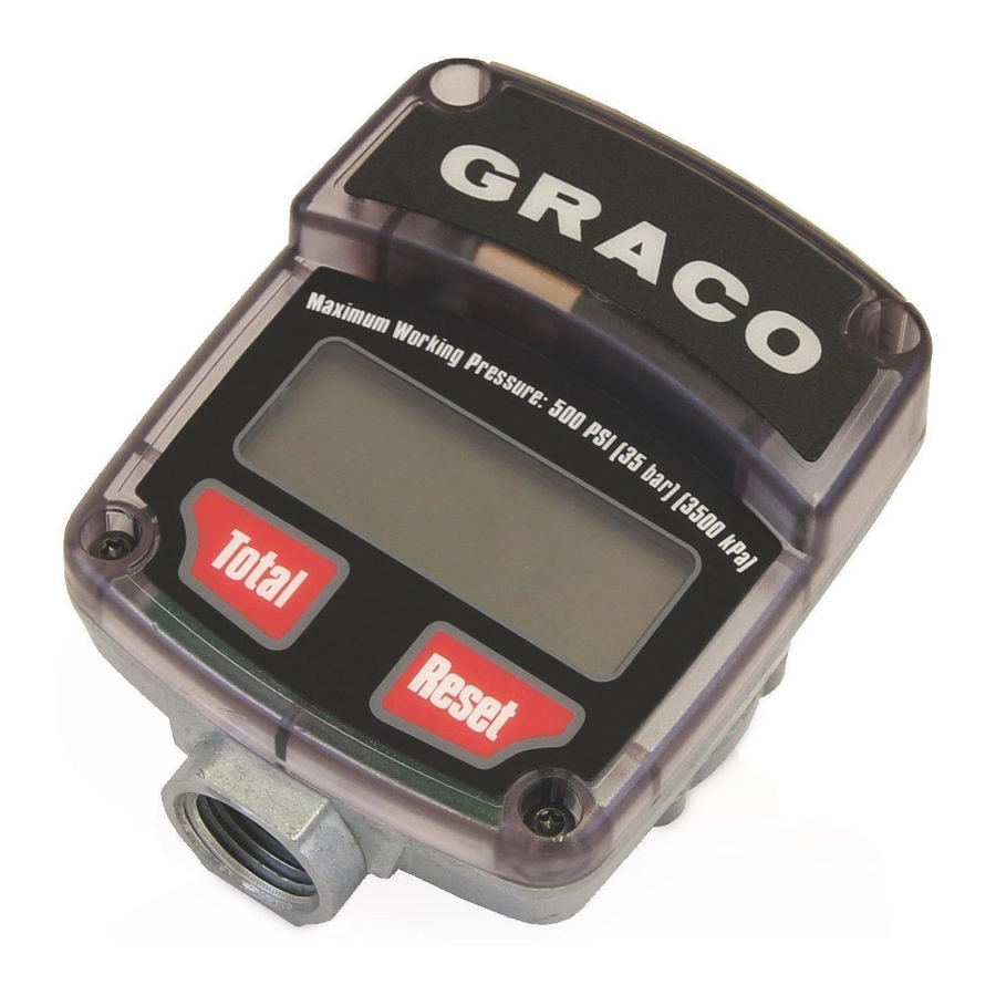
Inline
Electronic Meter
For use with petroleum-based and synthetic oil, antifreeze, and windshield washer fluid
only.
Model: 239824
500 psi (3.4 MPa, 34 bar) Maximum Working Pressure
5 gpm (19 lpm) Maximum Flow Rate
Important Safety Instructions
Read all warnings and instructions in this manual.
Save these instructions.
308687L
EN
Advertisement
Table of Contents

Subscribe to Our Youtube Channel
Related Manuals for Graco IM5


Summary of Contents for Graco IM5
- Page 1 Instructions - Parts List ™ Inline Electronic Meter 308687L For use with petroleum-based and synthetic oil, antifreeze, and windshield washer fluid only. Model: 239824 500 psi (3.4 MPa, 34 bar) Maximum Working Pressure 5 gpm (19 lpm) Maximum Flow Rate Important Safety Instructions Read all warnings and instructions in this manual.
- Page 2 Warnings Warnings The following warnings are for the setup, use, grounding, maintenance, and repair of this equipment. The exclama- tion point symbol alerts you to a general warning and the hazard symbols refer to procedure-specific risks. When these symbols appear in the body of this manual or on warning labels, refer back to these Warnings. Product-spe- cific hazard symbols and warnings not covered in this section may appear throughout the body of this manual where applicable.
- Page 3 Warnings EQUIPMENT MISUSE HAZARD Misuse can cause death or serious injury. • Do not operate the unit when fatigued or under the influence of drugs or alcohol. • Do not exceed the maximum working pressure or temperature rating of the lowest rated system component.
-
Page 4: Installation
The meters must be installed in-line as part of a dispense system as shown in Fig. 1. The typical installation shown is only a guide for selecting and installing an in-line meter; it is not an actual system design. Contact your Graco dis- tributor for assistance in designing a system to suit your needs. -
Page 5: Factory Settings
Installation Grounding The equipment must be grounded to reduce the risk of static sparking. Static sparking can cause fumes to ignite or explode. Grounding provides an escape wire for the electric current. Pump: follow the manufacturer’s recommendations. Air and fluid hoses: use only grounded hoses. Air compressor: follow manufacturer’s recommenda- tions. -
Page 6: Operation
Operation Operation Sleep Mode The meter automatically shuts down the display after one minute of non-use. . 2: Example of Total for Last Dispense Cycle Activation Mode There are two ways to activate the display: • Press any button on the keypad to wake up the dig- ital display. - Page 7 Operation Changing the Measurement Units and number may vary slightly due to temperature or flow rate. Calibration Factor NOTE: A one liter Weights and Measures approved Calibration container is required for calibration. Fluid Number oil (10W-30) This meter is factory calibrated to dispense 10W-30 gear lube motor oil at 70_ F (21_ C) at 2.0 gpm (7.6 lpm) and is automatic transmission fluid...
- Page 8 Service Service Pressure Relief Procedure NOTICE Follow the Pressure Relief Procedure whenever To avoid damaging the electronic components of the you see this symbol. control: • Do not remove the black cover over the electronic area when you replace the battery. There are no user-replaceable components under this cover.
-
Page 9: Battery Replacement Procedure
Service Battery Replacement Procedure 5. Install the electronic control to the metering unit (4), aligning the longer screws boss on the meter hous- . 5) ing with the counter bore in the plastic housing. 6. Install the four screws (3) holding the electronic control (1) to the metering unit (4) together. - Page 10 Service 4. Remove all gasket material from the metering unit (4). 5. Assemble adhesive side of new gasket (2) to meter- ing unit (4). 6. Replace battery (see Battery Replacement Proce- dure, page 9). NOTICE To avoid pinching the battery wires, install the bat- tery as shown in F .
-
Page 11: Troubleshooting
Troubleshooting Troubleshooting Problem Cause Solution Battery icon is shown on the display Battery is low Replace the battery. See Battery Replacement Procedure, page 9 and Technical Data, page 13 for recommended battery. Digital display does not activate Battery is low Replace the battery. - Page 12 Parts Parts Accessories Shutoff Valve: 108458 Install upstream from the meter. Shuts off fluid supply from the pump.1/2-14 npt(f) both ends. Strainer Kit: 239876 Includes strainer and o-ring. Install the strainer before the meter or before the valve on the meter/valve combination. Install the o-ring after the strainer to hold the strainer in place.
-
Page 13: Technical Data
Technical Data Technical Data IM5 Inline Electronic Meter Metric Flow range 0.5 to 5 gpm 1.9 to 19 lpm Maximum working pressure 500 psi 3.4 MPa, 34 bar Minimum working pressure 5 psi 34 kPa, 0.3 bar Weight 0.82 kg Weight 1.8 lbs... -
Page 14: Graco Standard Warranty
With the exception of any special, extended, or limited warranty published by Graco, Graco will, for a period of twelve months from the date of sale, repair or replace any part of the equipment determined by Graco to be defective.
Need help?
Do you have a question about the IM5 and is the answer not in the manual?
Questions and answers