Table of Contents
Advertisement
Quick Links
Instructions - Parts List
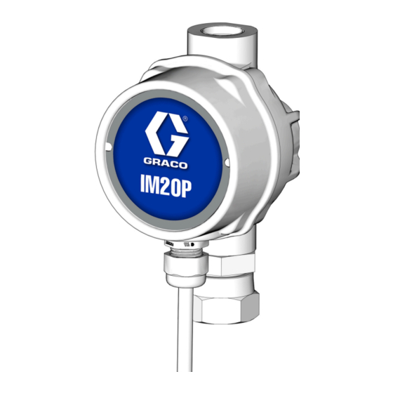
IM20P Meter
For dispensing of petroleum based oils and anti-freeze. For professional use only.
Not approved for use in explosive atmospheres or hazardous (classified) locations.
Model IM20P
1500 psi (10.3MPa,103 bar) Maximum Working
Pressure
Important Safety Instructions
Read all warnings and instructions in this
manual before using the equipment.
Save these instructions.
3A8625A
EN
Advertisement
Table of Contents

Summary of Contents for Graco IM20P
- Page 1 Instructions - Parts List IM20P Meter 3A8625A For dispensing of petroleum based oils and anti-freeze. For professional use only. Not approved for use in explosive atmospheres or hazardous (classified) locations. Model IM20P 1500 psi (10.3MPa,103 bar) Maximum Working Pressure Important Safety Instructions Read all warnings and instructions in this manual before using the equipment.
-
Page 2: Models
Models Models In-Line Pulse Meter Model No. Inlet Outlet Thread 133480 3/4 in. 3/4 in. 3A8625A... -
Page 3: Table Of Contents
Installation....... . . 6 Typical Installation: IM20P ....6 Grounding. -
Page 4: Warnings
Warnings Warnings The following warnings are for the setup, use, grounding, maintenance, and repair of this equipment. The exclamation point symbol alerts you to a general warning and the hazard symbols refer to procedure-specific risks. When these symbols appear in the body of this manual or on warning labels, refer back to these Warnings. Product-specific hazard symbols and warnings not covered in this section may appear throughout the body of this manual where applicable. - Page 5 Warnings WARNING EQUIPMENT MISUSE HAZARD Misuse can cause death or serious injury. • Do not operate the unit when fatigued or under the influence of drugs or alcohol. • Do not exceed the maximum working pressure or temperature rating of the lowest rated system component.
-
Page 6: Installation
. 1 is only a guide. The components shown are typical; however it is not a com- plete system design. Contact your Graco distributor for assistance in designing a system to suit your needs. Addition- ally, these dispense valves can be installed on a console. -
Page 7: Grounding
Fluid supply container: follow local code. drain valves in the system. IM20P meters: use thread sealant when connecting the 4. Leave the drain valve open until ready to pressurize meter to the hose. Do not use PTFE tape on the pipe the system. -
Page 8: Pre-Installation Procedure
Installation Installation of Meter The reference letters used in the instructions on this page refer to Typical Installation, F . 1, page 6. To install a new meter in an existing installation, begin with Step 1 and 2. Pre-Installation Procedure To install a new meter in a new installation, begin with Step 3. -
Page 9: Operation
Operation Operation The meter requires a Logic Control Device to operate. The meter sensor design allows for both PNP and NPN The Logic Control Device interprets pulse signals from Logic Controller Devices (F . 4). the meter and converts them into a fluid quantity. . -
Page 10: To Verify The Accuracy
Operation To Verify the Accuracy 1. Use a clean, calibrated container. NOTE: If using a single container, be sure to clean it after each dispense. 2. Set the pump air pressure at the lowest possible setting for dispensing fluid. 3. Place the tip of the nozzle at the bottom of the cali- brated container. -
Page 11: Recycling And Disposal
Recycling and Disposal Recycling and Disposal End of Product Life At the end of the product’s useful life, dismantle and recycle it in a responsible manner. • Perform the Pressure Relief Procedure. • Drain and dispose of fluids according to applicable regulations. -
Page 12: Troubleshooting
Increase pump pressure. Shut off valve is not fully open. Fully open shut off valve. Foreign material is jammed in the Contact your local Graco distributor meter element. for repair or replacement. Fluid leaks from swivel (5) Swivel (5) is loose. -
Page 13: Notes
NOTES: NOTES: 3A8625A... -
Page 14: Parts
Parts Parts Torque to 15 - 25 in-lb (1.7 - 2.8 N•m) Excessive torque will crack the casting. Torque to Only tighten fittings 2.5+ 0.5 turns past finger tight. 3A8625A... - Page 15 Parts Part Number Ref. Part Description Qty. 25E383 METER, sub-assembly 2† 129949 SEAL, bezel 3† 25U382 CONTROL, electronics 4† 131172 SCREW, Torx Pan HD 118459 FITTING, swivel, 3/4 in. † Parts included in Kit 133490 (purchase separately). 3A8625A...
-
Page 16: Technical Specifications
Technical Specifications Technical Specifications IM20P In-Line Pulse Meter Metric Recommended maximum flow rate (under normal operating conditions) 75.7 lpm IMP20 In-line Meter 20 gpm Minimum flow rate (under normal operating conditions) IMP20 In-line Meter 0.25 gpm 0.95 lpm Meter Pressure Loss: Tested in 10W oil at 70°F (21°C). -
Page 17: Pressure Drop Chart
Pressure Drop Chart Pressure Drop Chart ISO 46 Hydraulic Fluid California Proposition 65 CALIFORNIA RESIDENTS WARNING: Cancer and reproductive harm – www.P65warnings.ca.gov. 3A8625A... -
Page 18: Graco Standard Warranty
With the exception of any special, extended, or limited warranty published by Graco, Graco will, for a period of twelve months from the date of sale, repair or replace any part of the equipment determined by Graco to be defective.


Need help?
Do you have a question about the IM20P and is the answer not in the manual?
Questions and answers