Banner DF-G1 Install Sheet
Expert fiber amplifier advanced sensor with dual digital displays for use with plastic and glass fiber optic assemblies
Hide thumbs
Also See for DF-G1:
- Manual (28 pages) ,
- Quick start manual (11 pages) ,
- Installation manual (11 pages)
Table of Contents
Advertisement
Quick Links
DF-G1 - Expert Fiber Amplifier Install Sheet
Advanced sensor with dual digital displays for use with plastic and glass fiber optic assemblies
For the latest technical information about this product, including specifications, dimensions, and wiring, see
Overview
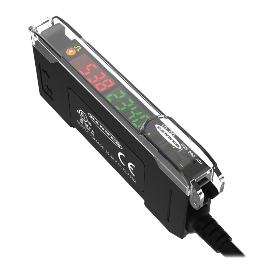
Figure 1. DF-G1 Model Features
Models
Model
DF-G1-NS-2M
DF-G1-PS-2M
DF-G1-NS-Q3
DF-G1-PS-Q3
DF-G1-NS-Q7
DF-G1-PS-Q7
WARNING: Not To Be Used for Personnel Protection
Never use this product as a sensing device for personnel protection. Doing so could lead to serious injury or death. This
product does NOT include the self-checking redundant circuitry necessary to allow its use in personnel safety applications. A sensor
failure or malfunction can cause either an energized or de-energized sensor output condition.
Hookups
NPN Models
For cable options, see
http://www.bannerengineering.com
P/N 161275 Rev. A
For Sales and Support, Contact Walker EMD • Toll-free: (800) 876-4444 • Tel: (203) 426-7700 • Fax: (203) 426-7800 • www.walkeremd.com
Outputs
Connector*
Single NPN
2 m (6.5') cable, 4-wire
Single PNP
Single NPN
150 mm (6") PVC pigtail, M8 Pico QD
connector, 4-pin
Single PNP
Single NPN
Integral M8 Pico QD connector, 4-pin
Single PNP
1/6/2012
www.BannerEngineering.com
1
Output LED
2
LO/DO Switch
3
RUN/PRG/ADJ Mode Switch
4
Lever Action Fiber Clamp
5
Red Signal Level
6
Green Threshold
7
+/SET/- Rocker Button
* Cordset Options: A model with a QD connector requires a
mating cordset. For 9 m cable, change the suffix 2M to 9M in
the 2 m model number (example, DF-G1-NS-9M). For M12
Euro QD pigtail change the suffix 2M to Q5 in the 2 m model
number (example, DF-G1-NS-Q5).
PNP Models
Key
2
1
3
4
1 = Brown
2 = White
3 = Blue
4 = Black
0 161275
2
Advertisement
Table of Contents

Related Manuals for Banner DF-G1


Summary of Contents for Banner DF-G1
- Page 1 Model Outputs Connector* mating cordset. For 9 m cable, change the suffix 2M to 9M in the 2 m model number (example, DF-G1-NS-9M). For M12 DF-G1-NS-2M Single NPN 2 m (6.5') cable, 4-wire Euro QD pigtail change the suffix 2M to Q5 in the 2 m model...
-
Page 2: Top Panel Interface
The output LED provides a visible indication when the output is activated. Remote Input For more information about how to perform TEACH/SET methods and to program the sensor remotely, see the DF-G1 Manual. Run Mode Run mode allows the sensor to operate normally and prevents unintentional programming changes. The +/SET/- rocker button is disabled during RUN mode, except when... -
Page 3: Program Mode
DF-G1 - Expert Fiber Amplifier Install Sheet Program Mode Program (PRG) mode allows the following set- tings to be programmed in the DF-G1 : Factory Default Settings: Setting Factory Default Threshold 2026 TEACH Selection Two-Point TEACH Response Speed Standard - 500 us... -
Page 4: Adjust Mode
DF-G1 - Expert Fiber Amplifier Install Sheet Adjust Mode Sliding the RUN/PRG/ADJ mode switch to the ADJ position allows the user to perform Expert TEACH/SET methods and Manual Adjustment of the threshold(s). Two-Point TEACH • Establishes a single switching threshold •... -
Page 5: Dynamic Teach
DF-G1 - Expert Fiber Amplifier Install Sheet Dynamic TEACH • Teaches on-the-fly • Establishes a single switching threshold • Threshold can be adjusted using “+” and “-” rocker button (Manual Adjust) Dynamic TEACH is best used when a machine or process may not be stopped for teaching. The sensor learns during actual sensing conditions, taking multiple samples of the light and dark conditions and automatically setting the threshold at the optimum level (see Figure below). -
Page 6: Window Set
DF-G1 - Expert Fiber Amplifier Install Sheet Window SET • Sets window thresholds that extend a programmable % offset above and below the presented condition • All other conditions (lighter or darker) cause the output to change state • Sensing window center can be adjusted using “+” and “-” rocker button (Manual Adjust) •... -
Page 7: Light Set
DF-G1 - Expert Fiber Amplifier Install Sheet Light SET • Sets a threshold a programmable % offset below the presented condition • Changes output state on any condition darker than the threshold condition • Threshold can be adjusted using “+” and “-” rocker button (Manual Adjust) •... - Page 8 DF-G1 - Expert Fiber Amplifier Install Sheet Dark SET • Sets a threshold a programmable % offset above the presented condition • Any condition lighter than the threshold condition causes the output to change state • Threshold can be adjusted using “+” and “-” rocker button (Manual Adjust) •...
-
Page 9: Calibration Set
DF-G1 - Expert Fiber Amplifier Install Sheet Calibration SET • Sets a threshold exactly at the presented condition • Threshold can be adjusted using “+” and “-” rocker button (Manual Adjust) A single sensing condition is presented, and the sensor positions a threshold exactly at the presented condition. When a condition lighter than the threshold is sensed, the... -
Page 10: Troubleshooting
This warranty does not cover damage or liability for the improper application or installation of Banner products. This warranty is in lieu of any other warranty either expressed or implied.
Need help?
Do you have a question about the DF-G1 and is the answer not in the manual?
Questions and answers