Advertisement
Switching Threshold
Models
D12EN6FV
Just above the "dark"
condition
D12EP6FV
D12E2N6FV
Midway between "dark"
and "light" conditions
D12E2P6FV
Switching Threshold
Models
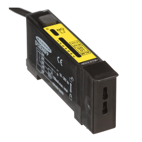
D12EN6FP
Just above the "dark"
condition
D12EP6FP
D12E2N6FP
Midway between "dark"
and "light" conditions
D12E2P6FP
**NOTE:9 m (30') cables are available by adding suffix "W/30" to the model number of any cabled sensor (e.g., D12EN6FP W/30)
Printed in USA
D12 Expert Series –
One-button programmable sensors for use with glass or plastic fibers
• Fiber optic sensors for DIN rail mounting; 10 to 30V dc operation
• Visible red (680 nm) light source; models for use with either glass or plastic fibers
• High optical sensing power when needed, also excels at low-contrast sensing
• Easy TEACH-mode programming automatically adjusts sensitivity to optimal setting*
• D12E sensors are designed for low-contrast sensing applications (switching
threshold set to just above the "dark" condition)
• D12E2 sensors set their switching threshold midway between the "dark" and
"light" conditions to ignore subtle changes, such as web flutter
• Output may be programmed for either light or dark operate
• Fast 200 microsecond sensing response; Programmable 40 millisecond pulse
stretcher
• Secure one-button programming is easy to use; one button sets both TEACH and
sensor configuration settings
• 7-segment LED bargraph indicates relative received signal strength and sensing
contrast, programming status, and diagnostic trouble warnings
• Marginal sensing alarm
• Separate input allows remote programming by an external device, such as a
switch or a process controller
D12 Expert Series Glass Fiber Optic Models
Cable**
Setting
2 m (6.5')
D12 Expert Series Plastic Fiber Optic Models
Cable**
Setting
2 m (6.5')
IMPORTANT: SEE SAFETY USE WARNING ON PAGE 4
TEACH-Mode Fiber Optic Sensors
D12 Expert Features
Supply
Output Type
Voltage
NPN (sinking)
PNP (sourcing)
10-30V dc
NPN (sinking)
PNP (sourcing)
Supply
Output Type
Voltage
NPN (sinking)
PNP (sourcing)
10-30V dc
NPN (sinking)
PNP (sourcing)
*U.S. Patent #5808296
Maximum Range
Range varies by sensing mode and fiber
optics used; see page 11.
Maximum Range
Range varies by sensing mode and fiber
optics used; see page 12.
P/N 41974G8B
Advertisement
Table of Contents


Need help?
Do you have a question about the Expert D12 Series and is the answer not in the manual?
Questions and answers