Advertisement

Quick Links

D10—Discrete Output
Datasheet
Low-cost, 10 to 30 V dc Sensor for use with Plastic Fiber Optics
WARNING: Not To Be Used for Personnel Protection
Never use this device as a sensing device for personnel protection. Doing so could lead to
serious injury or death. This device does not include the self-checking redundant circuitry necessary
to allow its use in personnel safety applications. A sensor failure or malfunction can cause either an
energized or de-energized sensor output condition.
Models
Red Beam
Green Beam
(660 nm)
(525 nm)
D10AFP
D10AFPG
D10AFPQ
D10AFPGQ
D10AFPY
D10AFPGY
D10AFPYQ
D10AFPGYQ
Features
12-Turn Sensitivity (Gain)
Control and Indicator
Turn Sensitivity control
clockwise to increase Gain
Delay Selector
LO/DO Select
Switch
1 To order the 9 m (30 ft) PVC cable model, add the suffix "W/30" to the cabled model number. For example, D10AFP W/30. Models with a quick disconnect
require a mating cordset.
Original Document
118431 Rev. B
Models available with visible red (660 nm) or visible green (525 nm) LED light
source
Sleek, ultra-slim 10 mm housing, mounts to standard 35 mm DIN rail
Solid-state, bipolar discrete outputs: one current sourcing (PNP) and one current
sinking (NPN)
High-speed models: 200-microsecond output response
Standard models: 500-microsecond output response plus crosstalk-avoidance
circuitry (for applications with multiple sensors)
Selectable Light/Dark Operate and 40 millisecond pulse stretcher (OFF-delay), via
two easy-to-operate slide switches
12-turn Sensitivity adjustment with relative position indicator
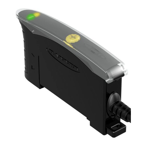
LED status indicators for Power ON and Light Sensed (AID
Models available with integral cable or Pico-style quick-disconnect
Response Time
500 microseconds
200 microseconds
Green
Power ON
LED
Yellow Signal
Strength LED
Switch
LED flashes
to indicate received
signal strength
14 November 2016
1
Cable
4-conductor 2 m (6.5 ft) Cable
4-pin Pico-style QD
4-conductor 2 m (6.5 ft) Cable
4-pin Pico-style QD
) indication
Output Type
Bipolar NPN/PNP Solid-state
118431

Advertisement

Table of Contents
loading

Summary of Contents for Banner D10 Series

  • Page 1 D10—Discrete Output Datasheet Low-cost, 10 to 30 V dc Sensor for use with Plastic Fiber Optics • Models available with visible red (660 nm) or visible green (525 nm) LED light source • Sleek, ultra-slim 10 mm housing, mounts to standard 35 mm DIN rail •...
  • Page 2: Wiring Diagram

    D10—Discrete Output Installation Installing Fibers and Housing Installing Fibers Mounting the D10 on a DIN Rail or the Mounting Bracket Slides up to release fibers Plastic fiber emitter port Plastic fiber receiver port DIN Rail (or included mounting bracket) Wiring Diagram NOTE: Quick disconnect (QD) 1 = Brown wiring diagrams are...
  • Page 3: Specifications

    Two LEDs: Green and Amber Green ON steady: Power ON Certifications ™ Amber flashing: Light Sensed Signal strength indicator (Banner’s AID Alignment Indicating Device—the faster the flash, the more light is received) P/N 118431 Rev. B www.bannerengineering.com - Tel: +1-763-544-3164...
  • Page 4 D10—Discrete Output Dimensions 10.5 ± 0.2 mm (typ.) (0.41") 7.6 mm 35.9 mm 0.30" (1.41") 9.8 mm Mounting Bracket (0.39") (included) 61.3 mm (2.42") 68.1 mm (2.68") All measurements are listed in millimeters [inches], unless noted otherwise. Included Bracket Dimensions 8.6 mm M3 Hardware included: 10.0 mm...
  • Page 5 D10—Discrete Output Performance Curves Opposed Mode Red Beam Models High-Speed Red Beam Models Green Beam Models 1000 1000 1000 D10AFP D10AFPY D10AFPG Opposed Mode D10AFPGY Red with PIT..U Opposed Mode Fiber Opposed Mode Red with PIT..U Green with PIT..U Fiber Fiber PIT46U PIT46U...
  • Page 6 Banner Engineering Corp. Limited Warranty Banner Engineering Corp. warrants its products to be free from defects in material and workmanship for one year following the date of shipment. Banner Engineering Corp. will repair or replace, free of charge, any product of its manufacture which, at the time it is returned to the factory, is found to have been defective during the warranty period.
  • Page 7: Data Sheet

    D10 Expert – Dual Discrete Outputs ™ Datasheet Advanced sensor for use with plastic fiber optics • Easy-to-set automatic Expert-style TEACH options including static, dynamic, and single-point programming plus manual adjustment for fine-tuning • 16-bit microcontroller and 12-bit Analog-to-Digital converter for high- performance, low-contrast sensing •...
  • Page 8: Programming Options

    3 See the Super High-Speed note under Sensor Setup. 4 Diffuse mode performance based on 90% reflectance white test card. 5 ø0.010-inch bifurcated fiber not recommended in these speed settings. Contact Banner Engineering for more information. www.bannerengineering.com - Tel: +1-763-544-3164...
  • Page 9: Sensor Programming

    ™ D10 Expert – Dual Discrete Outputs Sensor Programming Programming Procedures: Two push buttons, Dynamic (+) and Static (-), may be used to access and set programming parameters. For remote programming, connect a switch or digital input to the gray wire; length of the individual pulses is equal to the value T: 0.04 seconds ≤...
  • Page 10 ™ D10 Expert – Dual Discrete Outputs Method Action Result Push Button 6 Single-click both buttons simultaneously. Pointer icon: moves to the other channel indicator. Triple-pulse the remote line. NOTE: Triple-pulse will change the display, but will Remote Input 7 not save.
  • Page 11 ™ D10 Expert – Dual Discrete Outputs 3. TEACH the Output OFF condition. Method Action Result TEACH conditions accepted a. Present the Output OFF condition. Push Button • Display flashes “PASS,” b. Click the Static button. followed by a number (denoting contrast);...
  • Page 12 ™ D10 Expert – Dual Discrete Outputs 2. TEACH the Sensing Conditions. Method Action Result Present the Output ON/OFF conditions while Push Button continuing to hold the Dynamic button. Present the Output ON/OFF conditions while Remote Input continuing to hold the remote line low (to ground). 3.
  • Page 13 ™ D10 Expert – Dual Discrete Outputs Method Action Result • Display flashes “2nd” a. Present the sensing condition. Remote Input 12 b. Single-pulse the remote line. • Arrow icon turns red 2. SET the sensing condition. Method Action Result TEACH conditions accepted a.
  • Page 14 ™ D10 Expert – Dual Discrete Outputs Mode Threshold Offset (counts below taught signal value) Super High-Power Figure 8. Light Set Threshold Offset 1. Access the SET Mode. Method Action Result • Display flashes “1St” • Arrow icon turns red Push Button 13 Press and hold the Static (-) button >...
  • Page 15 ™ D10 Expert – Dual Discrete Outputs Single-Point Dark Set • Sets a threshold slightly above the taught condition Threshold position adjusted by • Any condition lighter than the threshold condition causes the Manual Adjust output to change state • Threshold position is adjustable using the “+”...
  • Page 16: Manual Adjust

    ™ D10 Expert – Dual Discrete Outputs Method Action Result Threshold condition accepted a. Present the Output OFF condition. • Display flashes “Sn6l,” then Push Button "dr" twice b. Five-click the Static button. • Sensor returns to RUN mode with new settings •...
  • Page 17 ™ D10 Expert – Dual Discrete Outputs 1. Access SETUP Mode. Method Action Result Press and hold both buttons concurrently for > 2 Push Button 18 seconds. The indicator arrow icon 1 is ON red. Remote Input 19 Double-pulse the remote line. 2.
  • Page 18: Advanced Setup

    ™ D10 Expert – Dual Discrete Outputs Method Action Result Indicator Arrow Icons 1 and 2 ON Red a. Click Dynamic (+) to toggle between Super-high-speed (50-μs response) selections. "SHS" (Complementary outputs; see note b. Click Static (-) to save selection and return to RUN mode.
  • Page 19: Push Button Lockout

    ™ D10 Expert – Dual Discrete Outputs Method Action Result a. Double-pulse the remote line to toggle between selections. Remote Input b. Single-pulse the remote line to save selection and advance to "Factory Default." 3. Return the sensor to the factory default settings, if desired. Method Action Result...
  • Page 20: Gate Input

    Self-Diagnostic Error Modes In the unlikely event that the setup parameters are lost or become corrupt, the display will continuously scroll: “USEr PSF Error.” Reteach the sensor to recover. If the problem persists, contact your Banner representative for further information. Gate Input The pink wire is configured as a gate input.
  • Page 21 ™ D10 Expert – Dual Discrete Outputs Dimensions 10.5 ± 0.2 mm (typ.) (0.41") 7.6 mm 35.9 mm 0.30" (1.41") 9.8 mm Mounting Bracket (0.39") (included) 61.3 mm (2.42") 68.1 mm (2.68") All measurements are listed in millimeters [inches], unless noted otherwise. Included Bracket Dimensions 8.6 mm M3 Hardware included:...
  • Page 22 Banner Engineering Corp. Limited Warranty Banner Engineering Corp. warrants its products to be free from defects in material and workmanship for one year following the date of shipment. Banner Engineering Corp. will repair or replace, free of charge, any product of its manufacture which, at the time it is returned to the factory, is found to have been defective during the warranty period.
  • Page 23 D10 Expert Series - Small Object Counter Datasheet Advanced sensor for small object counting • Easy-to-set selectable threshold with automatic compensation algorithm • Automatic compensation algorithm compensates for dust or contamination on the fiber optic array and for ambient temperature changes •...
  • Page 24 (stretched) to ensure accurate counting. The amount of increase is a user configurable percentage of the detection event duration; the default increase time is 50% more than the event duration. Banner calls this feature a Dynamic Event Stretcher (DES), and it prevents errant double counts of translucent gel-caps and other small objects of that type.
  • Page 25 D10 Expert Series - Small Object Counter Health Mode Alarm The Health Mode Alarm alerts you when preventative maintenance becomes necessary to ensure reliable sensing. The Health Mode output 2 is Active when the system is OK and operating normally. Health Mode output 2 becomes Inactive when the system is in a marginal state because of contamination.
  • Page 26: Sensor Setup

    D10 Expert Series - Small Object Counter Factory Default Settings. The following settings are preset at the factory; revert sensor to factory defaults using Advanced Setup procedure (see Advanced Setup on page 6) • Dark Operate (DO) • 50% DES •...
  • Page 27 D10 Expert Series - Small Object Counter Method Action Result Click Dynamic (+) to toggle between selections Light Operate: • Display flashes “lo” Push Button Click Static (-) to save selection and advance • L icon ON to “Dynamic Event Stretcher (DES)” Double-pulse remote line to toggle between Dark Operate: selections...
  • Page 28 D10 Expert Series - Small Object Counter Method Action Result Click Dynamic (+) to toggle between selections Arrow Icons 1 and 2 ON Red To return to Run mode, click the Static (-) High-speed (150-µs response): “HS” Push Button button OR To proceed to Advanced Setup, quad-click Static (-) button High-power (225-µs response): “HP”...
  • Page 29 D10 Expert Series - Small Object Counter Push Button Lockout • Prevents unwanted adjustments or tampering of the push buttons. • Push buttons can be enabled or disabled only from the remote line and only during normal RUN mode. Remote input pulse: 0.04 s ≤ T ≤ 0.8 s Method Action Result...
  • Page 30 D10 Expert Series - Small Object Counter Set Clear-State Light Level of Single-Point Window Method Action Result 1. Verify the fiber optic array is clean Display turns OFF and Arrow Icons 1 and 2 toggle 3 times and clear of any objects. green while the sensor is optimizing system settings.
  • Page 31 D10 Expert Series - Small Object Counter Specifications Required Fiber Optics Supply Voltage and Current PFCVA models (Custom fiber arrays and mounting configurations are 12 to 24 V dc (10% maximum ripple) at less than 65 mA, exclusive of possible. Consult factory for assistance with your small object counting load application.) Supply Protection Circuitry...
  • Page 32 D10 Expert Series - Small Object Counter Included Bracket Dimensions M3 Hardware included: 8.6 mm 10.0 mm (0.34") Lock Washer (2) (0.39") Flat Washer (2) Screws (2) 5.0 mm 2x 3.5 mm 5.0 mm (0.20") Hex Nuts (2) (0.20") (0.14") 2.5 mm (0.10") 35.1 mm (1.38")
  • Page 33 D10 Expert Series - Small Object Counter 14.5 mm [0.57”] 83 mm [3.27”] 30 mm 42 mm 25 mm [1.18”] [1.65”] [0.98”] 4x 3.2 mm dia [0.1260”] 25 mm [0.98”] 75 mm [2.95”] Figure 4. PFCVA-25X25-S and PFCVA-25X25-E 14.5 mm [0.57”] 83 mm [3.27”]...
  • Page 34 Banner Engineering Corp. Limited Warranty Banner Engineering Corp. warrants its products to be free from defects in material and workmanship for one year following the date of shipment. Banner Engineering Corp. will repair or replace, free of charge, any product of its manufacture which, at the time it is returned to the factory, is found to have been defective during the warranty period.
  • Page 35 D10 Expert - Analog and Discrete Outputs ™ Datasheet Advanced Sensor for use with Plastic Fiber Optics To view or download the latest technical information about this product, including specifications, dimensions, accessories, and wiring, see http://www.bannerengineering.com. Features • Easy-to-set automatic Expert-style TEACH options* including static, dynamic, and single- point programming plus manual adjustment for fine-tuning •...
  • Page 36 Output 1 displayed * Diffuse mode performance based on 90% reflectance white test card. ** ø0.010" bifurcated fiber not recommended in these speed settings. Contact Banner Applications for more information. Sensor Programming Programming Procedures: Two push buttons, Dynamic (+) and Static (-), may be used to access and set programming parameters. For remote programming, connect a switch or digital input to the gray wire;...
  • Page 37: Analog Outputs

    ™ D10 Expert - Analog and Discrete Outputs Returning to RUN mode: TEACH and SETUP modes each may be exited in one of two ways: by exercising the 60-second time-out, or by cancelling out of the process. In TEACH mode, the sensor will return to RUN mode without saving any of the new settings; in SETUP mode, the sensor will return to RUN mode but save all of the settings.
  • Page 38 ™ D10 Expert - Analog and Discrete Outputs Push Button Remote Result 0.04 sec. ≤ T ≤ 0.8 sec. Single-click both buttons simultaneously. Triple-pulse the remote line.* Pointer icon: moves to the other channel indicator. * Note: Triple-pulse will change the display, but will not save. To save Channel Select, make an adjustment to that channel as a TEACH, SET, or Sensor Setup.
  • Page 39 ™ D10 Expert - Analog and Discrete Outputs Method Action Result a. Present the Output ON condition Display flashes “2nd” Push Button b. Click the Static button a. Present the Output ON condition Remote Input b. Single-pulse the remote line 1.
  • Page 40 ™ D10 Expert - Analog and Discrete Outputs Push Button Remote Result 0.04 sec. ≤ T ≤ 0.8 sec. Press and hold Dynamic (+) • Display flashes “dYn” Hold remote line low (to ground). button. • Arrow icon turns red Access Dynamic TEACH Mode...
  • Page 41 ™ D10 Expert - Analog and Discrete Outputs 2. SET the sensing condition. Method Action Result TEACH conditions accepted • Display flashes “Sn6l,” then "Pt" twice a. Present the sensing condition Push Button b. Double-click the Static button • Sensor returns to RUN mode with new settings •...
  • Page 42 ™ D10 Expert - Analog and Discrete Outputs Method Action Result • Display flashes “1St” • Arrow icon turns red Push Button Press and hold the Static (-) button > 2 seconds • Display flashes “2nd” • Arrow icon turns red Remote Input 5 Single-pulse the remote line 2.
  • Page 43 ™ D10 Expert - Analog and Discrete Outputs Mode Threshold Offset (counts above taught signal value) Super High-Speed High-Speed High-Power Super High-Power Figure 12. Dark Set Threshold Offset 1. Access the Set Mode. Method Action Result • Display flashes “1St” •...
  • Page 44 ™ D10 Expert - Analog and Discrete Outputs Method Action Result Display briefly flashes the threshold setpoint value as it is being changed Push Button Click "+" to increase, or click "-" to decrease. Display flashes"inc" or "dEc" as the window size is adjusted Remote Input 7 Not available with remote programming...
  • Page 45 ™ D10 Expert - Analog and Discrete Outputs Push Button Remote Result 0.04 seconds ≤ T ≤ 0.8 seconds Click Static (-) to save selection and advance Single-pulse remote line to save 2 to 100 ms OFF- to "Display." selection and advance to Delay "Display."...
  • Page 46 ™ D10 Expert - Analog and Discrete Outputs Push Button Remote (0.04 s ≤ T ≤ 0.8 s) Result From "Power and Speed" mode, From "Power and Speed" mode, • Indicator Arrow Icons 1 quad-click the Static (-) button. quad-pulse the remote line. and 2 remain red •...
  • Page 47 Self-Diagnostic Error Modes In the unlikely event that the setup parameters are lost or become corrupt, the display will continuously scroll: “USEr PSF Error.” Reteach the sensor to recover. If the problem persists, contact your Banner representative for further information. Gate Input The pink wire is configured as a gate input.
  • Page 48 D10 Expert - Analog and Discrete Outputs Specifications Required Fiber-Optic Cable Adjustments Banner P-Series plastic fibers Push-button or remote programming of response time, OFF-delay, light/dark operate, and display Sensing Beam Indicators 680 nm visible red or 525 nm visible green, depending on model...
  • Page 49 ™ D10 Expert - Analog and Discrete Outputs Dimensions 10.5 ± 0.2 mm (typ.) (0.41") 7.6 mm 35.9 mm 0.30" (1.41") 9.8 mm Mounting Bracket (0.39") (included) 61.3 mm (2.42") 68.1 mm (2.68") Included Bracket Dimensions 8.6 mm M3 Hardware included: 10.0 mm (0.34") Lock Washer (2)
  • Page 50 Banner Engineering Corp. Limited Warranty Banner Engineering Corp. warrants its products to be free from defects in material and workmanship for one year following the date of shipment. Banner Engineering Corp. will repair or replace, free of charge, any product of its manufacture which, at the time it is returned to the factory, is found to have been defective during the warranty period. This warranty does not cover damage or liability for misuse, abuse, or the improper application or installation of the Banner product.
  • Page 51 D10 Expert Series with Bar Graph Display ™ and Discrete Output Datasheet Advanced sensor with dual displays for use with plastic fiber optics • Easy-to-read 8-segment light bar indicator for teach and signal strength readout, plus indicators for continuous readout of operating status (user configuration) •...
  • Page 52: Sensor Configuration

    ™ D10 Expert Series with Bar Graph Display and Discrete Output Power ON LED (green) Output LED (yellow) The sensor’s compact housing has a large, easy-to-see bar graph display plus bright LEDs for easy programming and status monitoring during operation. Bar graph display (red) Standard models have bipolar outputs, one each NPN and PNP.
  • Page 53 ™ D10 Expert Series with Bar Graph Display and Discrete Output Two-Point Static TEACH (Threshold) • Establishes a single switching threshold 2nd Taught 1st Taught Condition Condition • Threshold position is adjustable using “+” and “-” buttons (see Manual Adjust) Sensor positions threshold midway Static TEACH is the traditional setup method, used when two...
  • Page 54 ™ D10 Expert Series with Bar Graph Display and Discrete Output Dynamic TEACH and Adaptive Thresholds • Teach on-the-fly Darkest Taught Lightest Taught Condition Condition • Establishes a single switching threshold • Threshold position is adjustable using “+” and “-” buttons Sensor positions (Manual Adjust) threshold midway...
  • Page 55 ™ D10 Expert Series with Bar Graph Display and Discrete Output Single-Point Window Set • Sets a single ON condition that extends 12.5% above and below the taught condition • All other conditions (lighter or darker) result in OFF output •...
  • Page 56 ™ D10 Expert Series with Bar Graph Display and Discrete Output Single-Point Light Set • Sets a threshold 6.25% below the taught condition. • Any condition darker than the threshold condition causes the Threshold position output to change state adjusted by Manual Adjust •...
  • Page 57 ™ D10 Expert Series with Bar Graph Display and Discrete Output Single-Point Dark Set • Sets a threshold 6.25% above the taught condition Threshold position adjusted by • Any condition lighter than the threshold condition causes the Manual Adjust output to change state •...
  • Page 58: Setup Mode

    ™ D10 Expert Series with Bar Graph Display and Discrete Output Setup Mode Use Setup mode to change sensor output response for: • Light or Dark operate • 30-millisecond pulse stretcher (OFF-delay), if required Setup status • 200 μs high-speed response indicators If Setup mode configuration is interrupted and remains inactive for 60 seconds, the sensor returns to Run mode with the most...
  • Page 59: Enabling Or Disabling The Push Button

    ™ D10 Expert Series with Bar Graph Display and Discrete Output • Adjusts sensing window size (tolerance) for the single-point target condition • Press “+” to increase; press “-” to decrease The lighted bar graph LEDs move to reflect the increase or decrease. Enabling or Disabling the Push Button In addition to its programming function, the remote line may be used to disable the push buttons for security.
  • Page 60 ™ D10 Expert Series with Bar Graph Display and Discrete Output Specifications Sensing Beam Output Protection Standard sensors: 660 nm visible red or 525 nm visible green, Protected against output short-circuit, continuous overload, transient depending on model over-voltages, and false pulse on power-up Models with bussable power: 660 nm visible red Output Response Time Supply Voltage...
  • Page 61 ™ D10 Expert Series with Bar Graph Display and Discrete Output Dimensions 10.5 ± 0.2 mm (typ.) (0.41") 7.6 mm 35.9 mm 0.30" (1.41") 9.8 mm Mounting Bracket (0.39") (included) 61.3 mm (2.42") 68.1 mm (2.68") All measurements are listed in millimeters [inches], unless noted otherwise. Included Bracket Dimensions 8.6 mm M3 Hardware included:...
  • Page 62: Performance Curves

    ™ D10 Expert Series with Bar Graph Display and Discrete Output Performance Curves Red Beam Models Opposed Mode Diffuse Mode (Performance based on 90% reflectance white test card) 10000 1000 1000 1000 1000 PBT66U PBT26U PIT26U PIT66U PIT46U PIT16U PBT46U 1 mm 10 mm 100 mm...
  • Page 63 ™ D10 Expert Series with Bar Graph Display and Discrete Output Accessories Quick Disconnect Cordsets 6-Pin Snap-on M8/Pico-Style Cordsets Model Length Style Dimensions Pinout (Female) PKG6Z-2 2 m (6.5 ft) 32 Typ. Straight PKG6Z-9 9 m (30 ft) ø 9.0 PKW6Z-2 2 m (6.5 ft) 29 Typ.
  • Page 64 Banner Engineering Corp. Limited Warranty Banner Engineering Corp. warrants its products to be free from defects in material and workmanship for one year following the date of shipment. Banner Engineering Corp. will repair or replace, free of charge, any product of its manufacture which, at the time it is returned to the factory, is found to have been defective during the warranty period.

Table of Contents