Banner DF-G1-NS-2M Installation Manual
Dual display fiber amplifier
Hide thumbs
Also See for DF-G1-NS-2M:
- Quick start manual (11 pages) ,
- Manual (28 pages) ,
- Install sheet (11 pages)
Table of Contents
Advertisement
DF-G1 Expert
Installation Guide
Advanced sensor with dual digital displays for use with plastic and glass fiber optic assemblies.
For complete technical information about this product, including dimensions, accessories, and specifications, see
Banner Engineering website.
Overview
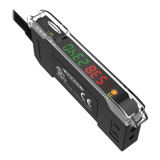
Figure 1. DF-G1 Model Features
WARNING: Not To Be Used for Personnel Protection
Never use this device as a sensing device for personnel protection. Doing so could lead to
serious injury or death. This device does not include the self-checking redundant circuitry necessary
to allow its use in personnel safety applications. A sensor failure or malfunction can cause either an
energized or de-energized sensor output condition.
Models
Model
Outputs
DF-G1-NS-2M
Single NPN
DF-G1-PS-2M
Single PNP
DF-G1-KS-2M
Dual outputs, 1 push-pull IO-Link and 1
PNP (complementary outputs)
DF-G1-NS-Q5
Single NPN
DF-G1-PS-Q5
Single PNP
DF-G1-KS-Q5
Dual outputs, 1 push-pull IO-Link and 1
PNP (complementary outputs)
DF-G1-NS-Q7
Single NPN
DF-G1-PS-Q7
Single PNP
Dual outputs, 1 push-pull IO-Link and 1
DF-G1-KS-Q7
PNP (complementary outputs)
1 Connector options:
•
A model with a QD connector requires a mating cordset .
•
For 9 m cable, change the suffix 2M to 9M in the 2 m model number (example, DF-G1-NS-9M).
•
For 150 mm (6 in) PVC pigtail, M8 Pico QD connector, 4-pin change the suffix 2M to Q3 in the 2 m model number (example, DF-G1-NS-Q3).
Phone: 800.894.0412 - Fax: 888.723.4773 - Web: www.clrwtr.com - Email: info@clrwtr.com
Dual Display Fiber Amplifier
™
1
Output LED
2
LO/DO Switch
3
RUN/PRG/ADJ Mode Switch
4
Lever Action Fiber Clamp
5
Red Signal Level
6
Green Threshold
7
+/SET/- Rocker Button
1
Connector
2 m (6.5 ft) cable, 4-wire
150 mm (6 in) PVC pigtail, M12 Euro QD connector,
4-pin
Integral M8 Pico QD connector, 4-pin
Advertisement
Table of Contents

Related Manuals for Banner DF-G1-NS-2M


Summary of Contents for Banner DF-G1-NS-2M
-
Page 1: Installation Guide
™ Installation Guide Advanced sensor with dual digital displays for use with plastic and glass fiber optic assemblies. For complete technical information about this product, including dimensions, accessories, and specifications, see Banner Engineering website. Overview Output LED LO/DO Switch RUN/PRG/ADJ Mode Switch... -
Page 2: Installation Instructions
™ DF-G1 Expert Dual Display Fiber Amplifier Installation Instructions Mounting Instructions Mount on a DIN Rail 1. Hook the DIN rail clip on the bottom of the DF-G1 over the edge of the DIN rail (1). 2. Push the DF-G1 up on the DIN rail (1). 3. -
Page 3: Fiber Adapters
NOTE: If a thin fiber with less than 2.2 mm outer diameter is used, install the fiber adapter provided with the fiber assembly to ensure a reliable fit in the fiber holder. Banner includes the adapters with all fiber assemblies. -
Page 4: Top Panel Interface
™ DF-G1 Expert Dual Display Fiber Amplifier IO-Link Models (C/Q) 18-30V dc Load Load NOTE: Open lead wires must be connected to a terminal block. Top Panel Interface Opening the dust cover provides access to the top panel interface. The top panel interface consists of the RUN/PRG/ADJ mode switch, LO/DO switch, +/SET/- rocker button, dual red/green digital displays, and output LED. -
Page 5: Run Mode
™ DF-G1 Expert Dual Display Fiber Amplifier Run Mode Run mode allows the sensor to operate normally and prevents unintentional programming changes. The +/SET/- rocker button is disabled during RUN mode, except when using Window SET, see Window SET on page 10. Phone: 800.894.0412 - Fax: 888.723.4773 - Web: www.clrwtr.com - Email: info@clrwtr.com... -
Page 6: Program Mode
™ DF-G1 Expert Dual Display Fiber Amplifier Program Mode Program (PRG) mode allows the following settings to be programmed in the DF-G1: Factory Default Settings: Setting Factory Default Threshold 2026 TEACH Two-Point Selection TEACH Response Standard - Speed 500 µs Offset Percent Auto Thresholds... -
Page 7: Adjust Mode
™ DF-G1 Expert Dual Display Fiber Amplifier Adjust Mode Sliding the RUN/PRG/ADJ mode switch to the ADJ position allows the user to perform Expert TEACH/SET methods and Manual Adjustment of the threshold(s). Two-Point TEACH • Establishes a single switching threshold •... -
Page 8: Dynamic Teach
™ DF-G1 Expert Dual Display Fiber Amplifier Method Action Result SET Button a. Present the first condition. Display: Flashes "2Pt tch" then holds on "1234 2nd" b. Click the SET rocker button Remote Input a. Present the first condition. b. Single-pulse the remote input. 3. - Page 9 ™ DF-G1 Expert Dual Display Fiber Amplifier Darkest Taught Lightest Taught Condition Condition Sensor positions threshold midway between taught conditions Output OFF Output ON Darkest Position Most Light (no signal) adjusted by (saturated Manual Adjust signal) Figure 3. Dynamic TEACH (Light Operate shown) The output ON and OFF conditions can be reversed using the LO/DO switch (see LO/DO Switch in Top Panel Interface page 4).
-
Page 10: Window Set
™ DF-G1 Expert Dual Display Fiber Amplifier Method Action Result SET Button Present ON and OFF conditions Display: Red - Signal Level; Green - Threshold Remote Input Present ON and OFF conditions 4. Exit Dynamic TEACH. Method Action Result SET Button Click the SET rocker button TEACH Accepted Displays alternate "PASS"... - Page 11 ™ DF-G1 Expert Dual Display Fiber Amplifier Sensing window center adjusted by Manual Adjust Sensor positions window thresholds a programmable % offset from the presented condition Output OFF Output ON Output OFF Darkest Condition Most Light (no signal) Presented (saturated signal) Figure 4.
-
Page 12: Light Set
™ DF-G1 Expert Dual Display Fiber Amplifier Method Action Result • Present sensing condition • Click the SET rocker button SET Button Threshold Condition Accepted Displays read "wInd SEt" then • Present sensing condition alternate "PASS" with % Offset 10 ; •... - Page 13 ™ DF-G1 Expert Dual Display Fiber Amplifier Threshold position adjusted by Manual Adjust Sensor positions threshold a programmable % offset below the presented condition Output OFF Output ON Darkest Condition Most Light (no signal) Presented (saturated signal) Figure 6. Light SET (Light Operate shown) Light SET and Manual Adjust Moves switching threshold value up or down to make adjustments •...
- Page 14 ™ DF-G1 Expert Dual Display Fiber Amplifier Method Action Result • Present sensing condition • Click the SET rocker button SET Button Threshold Condition Accepted Displays read "Lt SEt" then alternate • Present sensing condition "PASS" with % Offset 13 ; Sensor •...
- Page 15 ™ DF-G1 Expert Dual Display Fiber Amplifier Threshold position adjusted by Manual Adjust Sensor positions threshold a programmable % offset above the presented condition Output OFF Output ON Condition Darkest Most Light (no signal) Presented (saturated signal) Figure 7. Dark SET (Light Operate shown) Dark SET and Manual Adjust Moves switching threshold value up or down to make adjustments •...
-
Page 16: Calibration Set
™ DF-G1 Expert Dual Display Fiber Amplifier Method Action Result • Present sensing condition • Click the SET rocker button SET Button Threshold Condition Accepted Displays read "dr SEt" then alternate • Present sensing condition "PASS" with % Offset 16 ; Sensor •... - Page 17 ™ DF-G1 Expert Dual Display Fiber Amplifier ◦ GREEN display shows the switching threshold value ◦ 2 seconds after adjustment, the GREEN display will flash 3 times to confirm • Slide Mode switch to RUN to complete operation Remember: Auto Thresholding is automatically disabled in Calibration SET Follow these steps to perform a Calibration SET: Note: TEACH Selection must be programmed to CAL SEt (see Program Mode...
-
Page 18: Troubleshooting
™ DF-G1 Expert Dual Display Fiber Amplifier Troubleshooting Manual Adjustments Disabled Manual adjustments are disabled when Auto Thresholds are ON. If a manual adjustment is attempted while Auto Thresholds are ON, the Green display will flash Percent Minimum Difference after TEACH The Two-Point and Dynamic TEACH methods will flash a % minimum difference on the displays after a PASS or FAIL. -
Page 19: Specifications
Banner Engineering Corp Limited Warranty Banner Engineering Corp. warrants its products to be free from defects in material and workmanship for one year following the date of shipment. Banner Engineering Corp. will repair or replace, free of charge, any product of its manufacture which, at the time it is returned to the factory, is found to have been defective during the warranty period.
Need help?
Do you have a question about the DF-G1-NS-2M and is the answer not in the manual?
Questions and answers