Table of Contents
Advertisement
Quick Links
DF-G1 Expert
Installation Guide
Advanced sensor with dual digital displays for use with plastic and glass fiber optic assemblies.
For complete technical information about this product, including dimensions, accessories, and specifications, see
www.bannerengineering.com
Overview
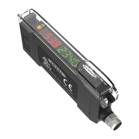
Figure 1. DF-G1 Model Features
WARNING: Not To Be Used for Personnel Protection
Never use this device as a sensing device for personnel protection. Doing so could lead to
serious injury or death. This device does not include the self-checking redundant circuitry necessary
to allow its use in personnel safety applications. A sensor failure or malfunction can cause either an
energized or de-energized sensor output condition.
Models
Model
Outputs
DF-G1-NS-2M
Single NPN
DF-G1-PS-2M
Single PNP
DF-G1-KS-2M
Dual outputs, 1 push-pull IO-Link and 1
PNP (complementary outputs)
DF-G1-NS-Q5
Single NPN
DF-G1-PS-Q5
Single PNP
DF-G1-KS-Q5
Dual outputs, 1 push-pull IO-Link and 1
PNP (complementary outputs)
DF-G1-NS-Q7
Single NPN
DF-G1-PS-Q7
Single PNP
Dual outputs, 1 push-pull IO-Link and 1
DF-G1-KS-Q7
PNP (complementary outputs)
1 Connector options:
•
A model with a QD connector requires a mating cordset .
•
For 9 m cable, change the suffix 2M to 9M in the 2 m model number (example, DF-G1-NS-9M).
•
For 150 mm (6 in) PVC pigtail, M8 Pico QD connector, 4-pin change the suffix 2M to Q3 in the 2 m model number (example, DF-G1-NS-Q3).
Original Document
161275 Rev. D
Dual Display Fiber Amplifier
™
and search 161999.
9 September 2015
1
Output LED
2
LO/DO Switch
3
RUN/PRG/ADJ Mode Switch
4
Lever Action Fiber Clamp
5
Red Signal Level
6
Green Threshold
7
+/SET/- Rocker Button
1
Connector
2 m (6.5 ft) cable, 4-wire
150 mm (6 in) PVC pigtail, M12 Euro QD connector,
4-pin
Integral M8 Pico QD connector, 4-pin
http://
161275
Advertisement
Table of Contents

Related Manuals for Banner Expert DF-G1-NS-2M


Summary of Contents for Banner Expert DF-G1-NS-2M
- Page 1 DF-G1 Expert Dual Display Fiber Amplifier ™ Installation Guide Advanced sensor with dual digital displays for use with plastic and glass fiber optic assemblies. For complete technical information about this product, including dimensions, accessories, and specifications, see http:// www.bannerengineering.com and search 161999. Overview Output LED LO/DO Switch...
-
Page 2: Installation Instructions
NOTE: If a thin fiber with less than 2.2 mm outer diameter is used, install the fiber adapter provided with the fiber assembly to ensure a reliable fit in the fiber holder. Banner includes the adapters with all fiber assemblies. -
Page 3: Wiring Diagrams
™ DF-G1 Expert Dual Display Fiber Amplifier FIBERS SENSOR Fiber Outer Diameter (mm) Adapter Color Ø 1.0 Black Ø 1.3 Ø 2.2 No adapter needed When connecting coaxial-type fiber assemblies to the amplifier, install the single-core fiber to the Transmitter port, and the multi-core fiber to the Receiver port. -
Page 4: Top Panel Interface
™ DF-G1 Expert Dual Display Fiber Amplifier Top Panel Interface Opening the dust cover provides access to the top panel interface. The top panel interface consists of the RUN/PRG/ADJ mode switch, LO/DO switch, +/SET/- rocker button, dual red/green digital displays, and output LED. RUN/PRG/ADJ Mode Switch The RUN/PRG/ADJ mode switch puts the sensor in RUN, PRG (Program), or ADJ (Adjust) mode. -
Page 5: Program Mode
™ DF-G1 Expert Dual Display Fiber Amplifier Program Mode Program (PRG) mode allows the following settings to be programmed in the DF-G1: Press and hold SET to exit Factory Default Settings: choice list without saving Setting Factory Default Threshold 2026 TEACH Two-Point Selection... -
Page 6: Adjust Mode
™ DF-G1 Expert Dual Display Fiber Amplifier Adjust Mode Sliding the RUN/PRG/ADJ mode switch to the ADJ position allows the user to perform Expert TEACH/SET methods and Manual Adjustment of the threshold(s). TEACH Procedures The instruction manual has detailed instructions for these TEACH modes: •... - Page 7 ™ DF-G1 Expert Dual Display Fiber Amplifier The output ON and OFF conditions can be reversed using the LO/DO switch. Window SET • Sets window thresholds that extend a programmable % offset above and below the presented condition • All other conditions (lighter or darker) cause the output to change state •...
- Page 8 ™ DF-G1 Expert Dual Display Fiber Amplifier • Recommended for applications where only one condition is known, for example a stable dark background with varying lighter targets • Program Mode on page 5 for programming the Offset Percent setting NOTE: Offset Percent MUST be programmed to Minimum Offset to accept conditions of no signal (0 counts).
- Page 9 ™ DF-G1 Expert Dual Display Fiber Amplifier Value PASS/FAIL Description 300 to 600% PASS The difference of the taught conditions sufficiently exceeds the required minimum, minor sensing variables will not affect sensing reliability 600% + PASS The difference of the taught conditions greatly exceeds the required minimum, very stable operation Percent Offset after SET The Window, Dark, and Light SET methods will flash a % offset on the displays after a PASS or FAIL.
-
Page 10: Specifications
Banner Engineering Corp Limited Warranty Banner Engineering Corp. warrants its products to be free from defects in material and workmanship for one year following the date of shipment. Banner Engineering Corp. will repair or replace, free of charge, any product of its manufacture which, at the time it is returned to the factory, is found to have been defective during the warranty period.
Need help?
Do you have a question about the Expert DF-G1-NS-2M and is the answer not in the manual?
Questions and answers