Table of Contents
Advertisement
Quick Links
Advertisement
Table of Contents

Related Manuals for ADJ HYDRO WASH X7


Summary of Contents for ADJ HYDRO WASH X7
- Page 1 HYDRO WASH X7 User Instructions...
- Page 2 ©2021 ADJ Products, LLC all rights reserved. Information, specifications, diagrams, images, and instructions herein are subject to change without notice. ADJ Products, LLC logo and identifying product names and numbers herein are trademarks of ADJ Products, LLC. Copyright protection claimed includes all forms and matters of copyrightable materials and information now allowed by statutory or judicial law or hereinafter granted.
-
Page 3: Table Of Contents
CONTENTS General Information Limited Warranty (USA Only) IP65 Notice Safety Guidelines Maintenance Guidelines Overview Torque Settings & IP Fixture Installation Connections DMX Setup Installation Instructions System Menu WiFly Control DMX Traits: Channel Functions & Values Color Macro Chart Target Modes Dimmer Curve Chart Error Codes Updating Software &... -
Page 4: General Information
GENERAL INFORMATION INTRODUCTION Please read and understand all instructions in this manual carefully and thoroughly before attempting to operate these products. These instructions contain important safety and use information. UNPACKING The products in this kit have been thoroughly tested and have been shipped in perfect operating condition. -
Page 5: Limited Warranty (Usa Only)
All shipping charges must be pre-paid. If the requested repairs or service (including parts replacement) are within the terms of this warranty, ADJ Products, LLC will pay return shipping charges only to a designated point within the United States. If the entire instrument is sent, it must be shipped in its original package. No accessories should be shipped with the product. - Page 6 IP NOTICE IP65 RATED An IP rated lighting fixture is one, which is commonly installed in outdoor environments and has been designed with an enclosure that effectively protects the ingress (entry) of external foreign objects such as dust and water. The International Protection (IP) rating system is commonly expressed as “IP” (Ingress Protection) followed by two numbers (i.e.
-
Page 7: Safety Guidelines
To guarantee a smooth operation, it is important to follow all instructions and guidelines in this manual. ADJ PRODUCTS LLC is not responsible for injury and/or damages resulting from the misuse of these devices due to the disregard of the information printed in this manual. Only qualified and/or certified personnel should perform installation of these devices and only the original rigging parts included with these devices should be used for installation. - Page 8 SAFETY GUIDELINES DO NOT position devices close to any FLAMMABLE MATERIALS while operating. DO NOT attempt installation and/or operation of devices without knowledge how to do so. DO NOT permit operation by persons who are not qualified to operate these types of devices. DO NOT shake devices, avoid brute force when installing and/or operating.
- Page 9 LEDs. This issue is not specific only to ADJ lighting fixtures, it is a common issue with lighting fixtures from all manufacturers. Although there is no true way to fully prevent this issue from happening, the guidelines below can prevent any potential damage from occurring if followed.
-
Page 10: Maintenance Guidelines
MAINTENANCE GUIDELINES DISCONNECT POWER BEFORE PERFORMING ANY MAINTENANCE! CLEANING Frequent cleaning is recommended to insure proper function, optimized light output, and an extended life. The frequency of cleaning depends on the environment in which the fixture operates: damp, smoky or particularly dirty environments can cause greater accumulation of dirt on the fixture’s optics. Clean the external lens surface at least every 20 days with a soft cloth to avoid dirt/debris accumulation. -
Page 11: Overview
OVERVIEW DOWN Button UP Button IP65 Locking Power Connectors In/Out SERVICE PORT Menu Screen MENU Button ENTER Button Gore Valve IP65 Locking 5-Pin DMX In/Out Safety Cable Attachment Point Carrying Handle Omega Bracket Mounting Hole OMEGA BRACKETS INSTALLATION Insert the Omega Brackets into the matching holes on the bottom of the fixture. Secure the Omega Brackets to the fixture by turning each quick-lock fastener ¼... -
Page 12: Torque Settings & Ip
TORQUE SETTINGS & IP TESTER TORQUE SETTINGS FOR SCREWS ALL SCREWS MUST BE TIGHTENED WITH A TORQUE DRIVER. All screws are Allen Head screws. Please see below for screw locations, screw quantity and torque settings. The number listed in the “#” column corresponds to the location on the fixture. - Page 13 TORQUE SETTINGS & IP TESTER TORQUE SCREW LOCATIONS...
-
Page 14: Fixture Installation
FIXTURE INSTALLATION Screw one clamp via a M12 screw and nut into the Omega Bracket. Insert the quick-lock fasteners of the Omega Bracket into the respective holes of the fixture base plate. NOTE: The clamp must be attached to the Omega Bracket before attaching the bracket to the fixture. Tighten the quick-lock fasteners fully clockwise. - Page 15 RUN OFF AND NOT COLLECT AROUND CABLE CONNECTIONS. The Hydro Wash X7 is fully operational in three different mounting positions, hanging upside-down, mounted sideways on trussing, or set on a flat level surface. Always use and install a safety cable as a safety measure to prevent accidental damage and/or injury in the event the clamp fails.
-
Page 16: Connections
CONNECTIONS ENSURE ALL CONNECTIONS AND END CAPS ARE PROPERLY SEALED WITH A DIELECTRIC GREASE (AVAILABLE AT MOST ELECTRICAL SUPPLIERS) TO PREVENT WATER CORROSION AND/OR ELECTRICAL SHORT CIRCUIT. TO MAINTAIN IP65 RATING INTEGRITY AND PREVENT WATER FROM ENTERING THE FIXTURE, ALL UNUSED CONNECTION RUBBER CAPS MUST BE SEALED... -
Page 17: Dmx Setup
DATA CABLE (DMX CABLE) REQUIREMENTS (FOR DMX AND PRIMARY/SECONDARY OPERATION): The Hydro Wash X7 can be controlled via DMX-512 protocol. Your unit and your DMX controller requires a 5-pin XLR connector for data input and data output. We recommend Accu-Cable DMX cables. If you are making your own cables, be sure to use standard 110-120 Ohm shielded cable (This cable may be purchased at almost all pro lighting stores). - Page 18 3 of a male XLR connector (DATA + and DATA -). This unit is inserted in the female XLR connector of the last unit in your daisy chain to terminate the line. Using a cable terminator (ADJ part number Z-DMX/T) will decrease the possibilities of erratic behavior.
- Page 19 In the case of the Hydro Wash X7, when in 15 Channel you should set the starting DMX address of the first unit to 1, the second unit to 16 (15 + 1), the third unit to 31 (16 + 15), and so on. (See the chart below for more details.)
-
Page 20: System Menu
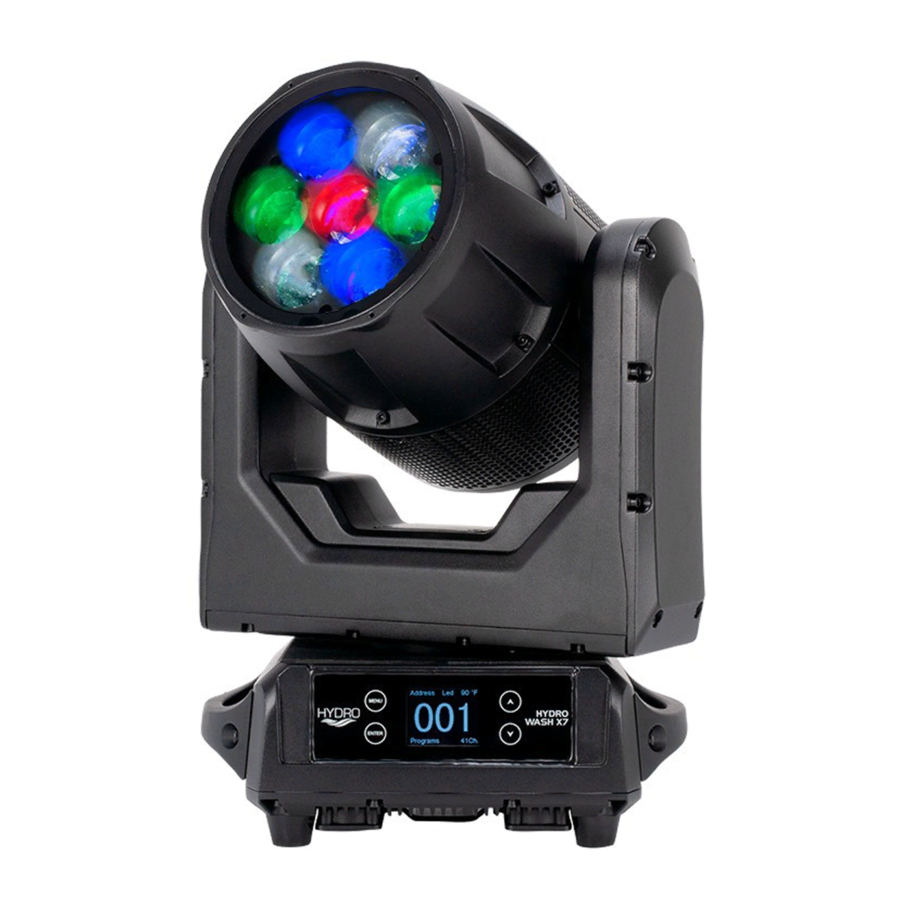
SYSTEM MENU The fixture includes an easy to navigate system menu control panel display where all necessary settings and adjustments are made. (See image below) During normal operation, pressing the MENU button once will access the fixture’s main menu. Once in the main menu, you can navigate through the different functions and access the sub-menus with the UP and DOWN buttons. - Page 21 SYSTEM MENU MAIN MENU SUB MENU OPTIONS / VALUES (Default Settings in BOLD) DESCRIPTION DMX Address 001-XXX DMX Addressing DMX Channel 15Ch / 17Ch / 41Ch DMX Channel Mode Selection SETTINGS Mode Hold Last / Blackout / Int Programs / Manual No DMX Status DMX Lost Status DMX: YES / NO...
- Page 22 SYSTEM MENU MAIN MENU SUB MENU OPTIONS / VALUES (Default Settings in BOLD) DESCRIPTION Mode 001 / 002 MODE 1 (001) 000-255 Tilt 000-255 Color 000-255 Red 1-7 000-255 Green 1-7 000-255 Blue 1-7 000-255 White 1-7 000-255 Color Macros 000-255 Shutter 000-255...
- Page 23 SYSTEM MENU MAIN MENU SUB MENU OPTIONS / VALUES (Default Settings in BOLD) DESCRIPTION Power On Time - XXXXXX Hours Total Running Time (Not Resettable) Fixture Life Time P-On Time-R - XXXXXX Hours Total Running Time (Resettable) P-On Time Reset - Pass Code = 050 Reset Total Running Time Total LED On Running Time LED On Time - XXXXXX Hours...
- Page 24 SYSTEM MENU DMX SETTINGS - The submenus listed under DMX SETTINGS are as follows: DMX Address, DMX Channel Mode, and No DMX Status. • DMX ADDRESS - In this submenu you can find and set your desired DMX address. • DMX CHANNEL MODE - In this submenu you can find and set your desired DMX channel mode.
- Page 25 SYSTEM MENU MANUAL CONTROL - This menu is for manual testing and manual control. Under MANUAL CONTROL, the fixture has two control modes; “MODE 1” and “MODE 2”. NOTE: NO DMX STATUS must be set to “Manual” when using Manual Control. INTERNAL PROGRAMS - This menu allows you to select 1 of 4 (0-4 internal programs to run.
- Page 26 SYSTEM MENU • FIXTURE TEMPS • LEDs Current - Current temperature of the LED’s is displayed. Max Resettable - Maximum LED temperature that has been recorded, before reset and after reset. (Resettable) Max Not Resettable - Overall maximum LED temperature that has been recorded. (Not Resettable) •...
-
Page 27: Wifly Control
With this feature you are able to control the unit with DMX without the need of XLR cables. Your DMX controller must be connected to a ADJ WiFly Transceiver to use this function. You are able to communicate up to 2500 feet/760 meters (open line of sight). - Page 28 DMX CHANNELS / VALUES / FUNCTIONS (17, 39, & 41 DMX Channels) Supports Software Version > 1.0 Features subject to change without notice *Rotation direction (Clockwise/Counter-Clockwise) and control of effects depends on head orientation and Pan/Tilt settings* MODE / CHANNEL VALUE FUNCTION CH 15...
- Page 29 DMX CHANNELS / VALUES / FUNCTIONS (17, 39, & 41 DMX Channels) Supports Software Version > 1.0 Features subject to change without notice *Rotation direction (Clockwise/Counter-Clockwise) and control of effects depends on head orientation and Pan/Tilt settings* MODE / CHANNEL VALUE FUNCTION CH 15...
- Page 30 DMX CHANNELS / VALUES / FUNCTIONS (17, 39, & 41 DMX Channels) Supports Software Version > 1.0 Features subject to change without notice *Rotation direction (Clockwise/Counter-Clockwise) and control of effects depends on head orientation and Pan/Tilt settings* MODE / CHANNEL VALUE FUNCTION CH 15...
-
Page 31: Color Macro Chart
COLOR MACRO CHART RGBA COLOR INTENSITY RGBA COLOR INTENSITY Color No. Color No. Value Value GREEN BLUE AMBER GREEN BLUE AMBER Color33 129-132 Color1 Color34 133-136 Color2 Color35 137-140 Color3 9-12 Color36 141-144 Color4 13-16 Color37 145-148 Color5 17-20 Color38 149-152 Color6 21-24... -
Page 32: Target Modes
TARGET MODES... -
Page 33: Dimmer Curve Chart
DIMMER CURVE CHART DIMMER 100% Time (ms) 0 Sec Rise Time Down Time 0 sec Fade Time 1 sec Fade Time Dimming Curve Ramp Effect Rise Time (ms) Down Time (ms) Rise Time (ms) Down Time (ms) Standard (default) Stage 1100 1540 1660... -
Page 34: Error Codes
ERROR CODES PRINT ERROR MESSAGE DESCRIPTION CPU-B Error CPU-B Error CPU-C Error CPU-C Error CPU-D Error CPU-D Error Pan Reset Error Pan: Reset Error Pan Encode Error Pan: Encode Error Tilt Reset Error Tilt: Reset Error Tilt Encode Error Tilt: Encode Error Zoom Reset Error Zoom: Reset Error HeadFan Start Error... - Page 35 DOWNLOAD FIXTURE SOFTWARE TO PC ONLY! (NO MAC SUPPORT) PLEASE CONTACT ADJ CUSTOMER SERVICE FOR FURTHER INFORMATION. Contact ADJ Customer Service to obtain the software update files. Copy the software files to a compatible USB flash drive. NOTE: MAKE SURE THESE SOFTWARE FILES ARE THE ONLY FILES LOADED ONTO THE USB FLASH DRIVE.
-
Page 36: Specifications
SPECIFICATIONS Light Source: • 7x Osram 40W RGBW (4-IN-1) LEDs Features: • IP65 outdoor rated – protects fixture from dust, sand, moisture and liquid • Motorized Zoom: 6 ~ 40-degrees • Firmware Upgrade: Update via IP65 USB port (with rubber protective covers over connections) •... - Page 37 DIMENSIONS (VERTICAL)
- Page 38 DIMENSIONS (HORIZONTAL)
- Page 39 FCC STATEMENT This device complies with Part 15 of the FCC Rules. Operation is subject to the following two conditions: (1) this device may not cause harmful interference, and (2) this device must accept any interference received, including interference that may cause undesired operation. FCC RADIO FREQUENCY INTERFERENCE WARNINGS &...
Need help?
Do you have a question about the HYDRO WASH X7 and is the answer not in the manual?
Questions and answers