Table of Contents
Advertisement
Quick Links
Advertisement
Table of Contents

Related Manuals for ADJ Eliminator Lighting FROST FX BAR W


Summary of Contents for ADJ Eliminator Lighting FROST FX BAR W
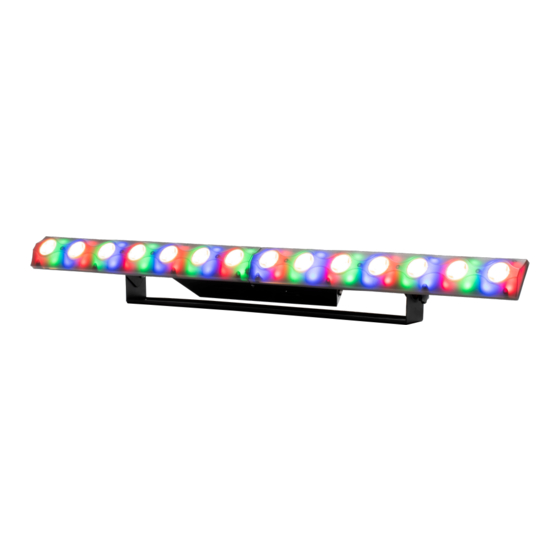
- Page 1 FROST FX BAR W User Instructions...
- Page 2 Product names used in this document may be trademarks or registered trademarks of their respective companies and are hereby acknowledged. All non-ADJ Products, LLC brands and product names are trademarks or registered trademarks of their respective companies.
-
Page 3: Table Of Contents
CONTENTS General Information Limited Warranty (USA Only) Safety Guidelines Overview Installation DMX Set Up DMX Addressing System Menu DMX Traits: Channel Functions & Values Color Macro Chart Dimmer Mode Chart Power Linking | Cleaning Specifications... -
Page 4: General Information
GENERAL INFORMATION INTRODUCTION Please read and understand all instructions in this manual carefully and thoroughly before attempting to operate these products. These instructions contain important safety and use information. UNPACKING The products in this kit have been thoroughly tested and have been shipped in perfect operating condition. -
Page 5: Limited Warranty (Usa Only)
All shipping charges must be pre-paid. If the requested repairs or service (including parts replacement) are within the terms of this warranty, ADJ Products, LLC will pay return shipping charges only to a designated point within the United States. If the entire instrument is sent, it must be shipped in its original package. No accessories should be shipped with the product. -
Page 6: Safety Guidelines
To guarantee a smooth operation, it is important to follow all instructions and guidelines in this manual. ADJ Products, LLC is not responsible for injury and/or damages resulting from the misuse of this fixture due to the disregard of the information printed in this manual. Only qualified and/or certified personnel should perform installation of this fixture and only the original rigging parts included with this fixture should be used for installation. - Page 7 S A F E T Y G U I D E L I N E S DO NOT TOUCH the fixture housing during operation. Turn OFF the power and allow approximately 15 minutes for the fixture to cool down before servicing. DO NOT shake fixture;...
-
Page 8: Overview
OVERVIEW Integrated Mounting Bracket and Safety Cable Attachment Point Omega Bracket Thumb Knob Mounting Hole Locking Power Locking Power Connector Output LCD Menu Control Display Connector Input Locking 3-Pin Locking 3-Pin ENTER Button DMX Input DMX Output DOWN Button ESC Button UP Button... -
Page 9: Installation
INSTALLATION FLAMMABLE MATERIAL WARNING Keep fixture at least 7.9in. (0.2m) away from any flammable materials, decorations, pyrotechnics, etc. ELECTRICAL CONNECTIONS A qualified electrician should be used for all electrical connections and/or installations. MINIMUM DISTANCE TO OBJECTS/SURFACES MUST BE 40 FEET (12 METERS) MAXIMUM TEMPERATURE OF EXTERNAL SURFACE 167°F (75°C) DO NOT INSTALL THE FIXTURE IF YOU ARE NOT QUALIFIED TO DO SO! Fixture MUST be installed following all local, national, and country commercial electrical and construction... - Page 10 INSTALLATION Screw one clamp each via a M12 screw and nut into the Omega brackets. Insert the quick-lock fasteners of the Omega brackets into the respective holes on the bottom of the Frost FX Bar W. Tighten the quick- lock fasteners fully clockwise. Pull a safety cable through the safety cable attachment points located on the base plate and over the trussing system or a safe fixation spot.
- Page 11 INSTALLATION When installing the unit, the trussing or area of installation must be able to hold 10 times the weight without any deformation. When installing, the unit must be secured with a secondary safety attachment, e.g. and appropriate safety cable. Never stand directly below the unit when mounting, removing, or servicing the unit.
-
Page 12: Dmx Set Up
S E T U P DMX-512: DMX is short for Digital Multiplex. This is a universal protocol used as a form of communication between intelligent fixtures and controllers. A DMX controller sends DMX data instructions from the controller to the fixture. DMX data is sent as serial data that travels from fixture to fixture via the DATA “IN”... - Page 13 XLR connector of the last unit in your daisy chain to terminate the line. Using a cable terminator (ADJ part number Z-DMX/T) will decrease the possibilities of erratic behavior. 5-Pin XLR DMX Connectors: Some manufactures use 5-pin DMX- 512 data cables for DATA transmission in place of 3-pin.
-
Page 14: Dmx Addressing
D M X A D D R E S S I N G All fixtures should be given a DMX starting address when using a DMX controller, so the correct fixture responds to the correct control signal. This digital starting address is the channel number from which the fixture starts to “listen”... -
Page 15: System Menu
SYSTEM MENU The fixture includes an easy to navigate system menu control panel display where all necessary settings and adjustments are made. During normal operation, pressing the ESC button once will return the current menu to the last menu. In the main menu, you can navigate through the different functions and access the sub-menus with the UP and DOWN buttons. -
Page 16: Dmx Traits: Channel Functions & Values
DMX TRAITS: CHANNEL FUNCTIONS & VALUES (6/8/14/14/17/56/60/66/69 DMX Channels) 6CH 8CH 14Ch 14CH 17CH 56CH 60CH 66CH 69CH Values Functions White Main Pixels 1-14 000‐255 0% ‐ 100% Red Background Color 1-14 000‐255 0% ‐ 100% Green Background Color 1-14 000‐255 0% ‐... - Page 17 DMX TRAITS: CHANNEL FUNCTIONS & VALUES (6/8/14/14/17/56/60/66/69 DMX Channels) 6CH 8CH 14Ch 14CH 17CH 56CH 60CH 66CH 69CH Values Functions Background Color 1-14 Shutter 000-031 Shutter Closed (LEDs OFF) 032-063 Shutter OPEN (LEDs ON) 064-095 Strobe effect slow to fast 096-127 Shutter OPEN (LEDs ON) 128-159 Pulse effect in sequences 160-191 Shutter OPEN (LEDs ON)
-
Page 18: Color Macro Chart
COLOR MACRO CHART RGB COLOR INTENSITY Color DMX VALUE GREEN BLUE R02 BASTARD AMBER R04 MEDIUM AMBER 8-15 R09 PALE AMBER GOLD 16-23 R316 GALLO GOLD 24-31 R21 GOLDEN AMBER 32-39 R26 LIGHT RED 40-47 R27 MEDIUM RED 48-55 R36 MEDIUM PINK 56-63 R339 BROADWAY PINK 64-71... -
Page 19: Dimmer Mode Chart
DIMMER MODE CHART Dimming Speed DMX Value Delay and Menu Display Time 0.1Sec. 0.2Sec. 0.3Sec. 0.4Sec. 0.5Sec. 0.6Sec. 0.7Sec. 0.8Sec. 0.9Sec. 1.0Sec. 1.5Sec. 2.0Sec. 3.0Sec. 4.0Sec. 5.0Sec. 6.0Sec. 7.0Sec. 8.0Sec. 9.0Sec. 10Sec. -
Page 20: Power Linking | Cleaning
POWER LINKING With this feature you can connect the fixtures to one another using the power cable input and output sockets. NOTE: USE CAUTION WHEN POWER LINKING OTHER FIXTURES AS THE POWER CONSUMPTION OF OTHER MODEL FIXTURES MAY EXCEED THE MAX POWER OUTPUT ON THIS FIXTURE! CHECK SILK SCREEN FOR MAX AMPS. -
Page 21: Specifications
SPECIFICATIONS Input Voltage: 110-240VAC 50-60Hz Power Supply: 55w Lamp: 14pcs 3W Cree Cool-white (6000k)+84pcs 5050 3in1 smd LED Control Mode: DMX512/ Auto mode/Sound mode/ Dimming: 0–100° Angle: 17° DMX Channel: CH06/CH08/Ch14/CH14/CH56/CH60/CH66/CH69 Display: 4 button LED display Connection: 3-pin Data in/out Power Connector in/out Material: Steel housing Dimensions:... - Page 22 DIMENSIONS...
Need help?
Do you have a question about the Eliminator Lighting FROST FX BAR W and is the answer not in the manual?
Questions and answers