Rehau NEA SMART 2.0 End User Manual
Hide thumbs
Also See for NEA SMART 2.0:
- Service manual (144 pages) ,
- End user manual (68 pages) ,
- Quick install manual (9 pages)
Table of Contents
Advertisement
Advertisement
Table of Contents

Related Manuals for Rehau NEA SMART 2.0


Summary of Contents for Rehau NEA SMART 2.0
- Page 1 End user manual The new generation of thermostats – NEA SMART 2.0...
-
Page 2: Table Of Contents
Content This user manual for the “NEA SMART 2.0 control End user manual Information and safety instructions system” is valid from January 2021. Introduction Operation via the Room unit This document is protected by copyright. The rights Displays on the Base, R- and U-Module... - Page 3 Enhancing lives...
-
Page 4: End User Manual
▪ Electrical or electronics engineer Intended use The NEA SMART 2.0 control system may only be In accordance with the international regulations as planned, installed and operated as described in these well as the comparable professions within your instructions and in the other documents belonging to specific national legal framework. -
Page 5: Introduction
▪ LAN/wireless LAN featured as standard NEA SMART 2.0 Room units/Room probes ▪ High-quality design ▪ LED matrix display ▪ Bus and wireless variant Fig. 02-1 NEA SMART 2.0 system (not all components of the system are shown) - Page 6 End user manual Functions and operation The NEA SMART 2.0 app is easy and convenient to use, and offers many features that make the system a What can the NEA SMART 2.0 system do? truly smart system. The basic function of the system is to heat the rooms...
- Page 7 End user manual All system components: Base 24 V / 230 V Room unit The base is a central control unit for underfloor heating and cooling systems and is normally located in the heating circuit manifold box. Up to 8 room control units The room unit operates the room temperature and can be connected to the base via bus or wireless tech- humidity sensor as well as an operating unit for the...
- Page 8 KNX Gateway Temperature sensor is connected to the The KNX gateway enables data transmission from the NEA SMART 2.0 U-Module to measure the flow and NEA SMART 2.0 control technology to a KNX system. return temperature of a mixed heating circuit.
- Page 9 Switching Relais 24 V / 230 V The switching relay is used to connect to triac outputs or relay outputs of the NEA SMART 2.0 24 V / 230 V control system and to control external devices, addi- tional actuators or to forward signals to other building...
-
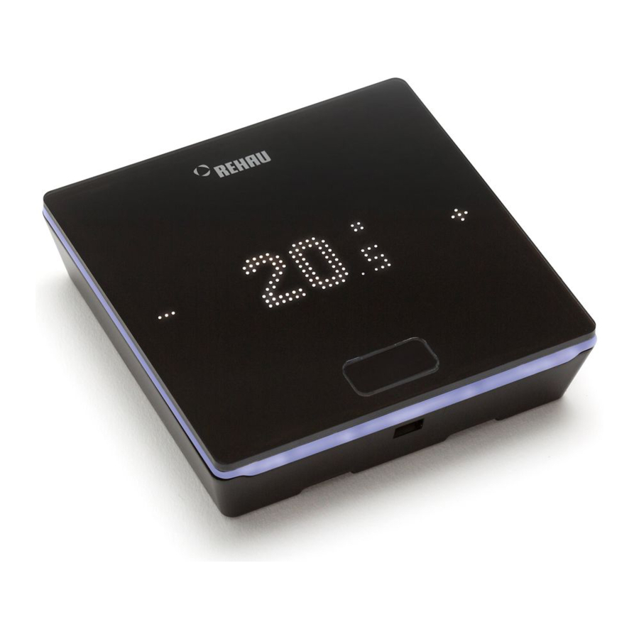
Page 10: Operation Via The Room Unit
It is activated by pressing the Home button. Only then the plus/minus symbols become visible. Flashing symbols or numbers can be modified. Fig. 03-1 NEA SMART 2.0 Room unit The Room unit is operated using the Home button and the +/- symbols. - Page 11 End user manual Display of temperature Transitional phase Reduced Transitional phase Reduced to Normal Shows the current room temperature or operating mode the desired room temperature. Party Party mode is active Display of room humidity Holiday Shows the relative humidity in the Holiday mode is active room.* Room unit locked...
- Page 12 End user manual Order of the displayed information Setting the desired temperature To activate the display, press the Home button once. To see the target value, press +/- once. 3s / Initial state Display of current room temperature Display of current humidity in the room Display of operating mode Heating or cooling Initial state...
- Page 13 End user manual Operating status The current operating status is displayed after pressing the Home button 4 times. It can be changed by pressing +/-. The current operating status is always When standby mode is selected, automatic frost displayed first. This means that the order can deviate protection is active.
-
Page 14: Displays On The Base, R- And U-Module
End user manual Displays on the Base, R- and U-Module NEA SMART 2.0 Base 24 V / 230 V Fig. 04-1 NEA SMART 2.0 Base 24 V / 230 V – labelling LED display Green: everything OK Blue: Cooling mode active... - Page 15 (L1/L2) Green: active NEA SMART 2.0 U-Module 24 V U-Module 24 V Fig. 04-3 NEA SMART 2.0 U-Module 24 V – labelling LED display Freely configurable potential-free contacts Green: Operating voltage OK Green: active Green: shows communication with master Digital input (window contact, dew point monitor ...)
-
Page 16: Operation Via Integrated Web
PC. The NEA SMART 2.0 Base may only be handled if the cover is in place on the NEA SMART 2.0 Base. If this is The IP address of the device is 192.168.0.2. not the case, the installer has to be called. - Page 17 End user manual Establishing a connection between the Base and the PC/tablet/smartphone Before performing the following steps, the transmit- ting function on the NEA SMART 2.0 Base must be switched on. WIFI/LAN By briefly pressing the right arrow button, it is possible to switch between the transmitting functions (none, direct connection, server connection).
- Page 18 End user manual Password: ******** Default WIFI WPA2 Key After selecting the REHAU network, the security key needs to be entered. The security key (default Wi-Fi WPA2 key) can be found on the label of the base station. After a few seconds, the PC/tablet/smartphone connects to the base station.
-
Page 19: Usage Of The Integrated Web
End user manual Usage of the integrated web pages Depending on the type of system, the integrated web pages offer the following options: ▪ Selection of the operating modes of the system: In order to ensure comfortable conditions and an ener- ▪... - Page 20 End user manual Room page: Extended room page: Fig. 06-3 Web page: Room page settings Here, the current target and actual temperature and the operating mode (here: heating mode, via time programme, currently “normal” mode) are displayed. The room temperature target value can be changed using the plus and minus symbols.
- Page 21 End user manual The auto-start function ensures that the desired room building, office building), the appropriate timer temperature is reached at the defined point in time. If programms are selected automatically. the auto-start function is not selected, the room is only heated or cooled to the new default value from the point in time selected in the timer programme.
- Page 22 KNX connection The KNX connection of the NEA SMART 2.0 system is suitable for exchanging data (setpoints, actual values, IT settings: operating modes and energy levels) between the Here, settings are made that allow the system to NEA SMART 2.0 system and a higher-level KNX...
-
Page 23: Usage Of The Nea Smart 2.0 App
End user manual Usage of the NEA SMART 2.0 App The NEA SMART 2.0 app can be found in the google ® Play Store and apple ® App Store. Using the app The NEA SMART 2.0 Base may only be handled if the No matter where you are, the NEA SMART 2.0 app... - Page 24 By briefly pressing the right arrow button, it is possible to switch between the transmitting functions (none, Insert the LAN cable into the NEA SMART 2.0 Base as direct connection, server connection). Press the right well as into the router/network socket.
- Page 25 < 1 sec Confirm by briefly pressing the OK button. WIFI/LAN The WIFI/LAN LED will start to light up permanently after no more than 2 minutes. The base station is now connected to the Internet and the REHAU server.
- Page 26 In this case, the sequence for activating the transmitting function can be started again from step 2. Setting up the NEA SMART 2.0 app After the Base is successfully connected to the Internet as described in the previous chapter, the app can be connected.
- Page 27 1. Scanning the QR code that is printed on the Base. 2. Entering the identification number and confirming. The software for the NEA SMART 2.0 system is continuously being developed and improved. An update via an internet connection is required to take advantage of all new and improved functions.
- Page 28 End user manual Useful tips Automatic update of the NEA SMART 2.0 APP (OTA) In order to have the latest version of the app on your devices always, we recommend activating the button Display weather data for the location of the installa- for automatic updates (OTA).
- Page 29 End user manual Update the display of the NEA SMART 2.0 APP It can happen that the app does not display the latest data from the Room units etc. A quick and easy update is necessary to bring the app up to date.
-
Page 30: Battery (Battery-Operated Thermostat Only)
Replace the batteries if the fault message “low battery” is displayed. To do so, open the housing of the NEA SMART 2.0 Room unit (see Fig. 8-1) with a screwdriver (recom- mended width: 5 mm). Fig. 08-3 NEA SMART 2.0 Room unit – close the lid... -
Page 31: Error Description
End user manual Error description Faults and possible causes The room does not get warm. ▪ The target temperature is set too low. ▪ A window is open and therefore the heating has switched to reduced mode. ▪ The battery of the thermostat is empty. Therefore, no data/commands can be sent to the system. -
Page 32: Technical Data Nea Smart
Technical data NEA SMART 2.0 NEA SMART 2.0 Room unit The NEA SMART 2.0 Room unit’s functional features are indicated by a suffix, such as TRW or HRB. The following naming system is used: NEA SMART 2.0 Room unit XXX... - Page 33 End user manual NEA SMART 2.0 Room probe’s The NEA SMART 2.0 Room probe’s features are indicated by a suffix, such as TBW or HBW. The following naming system is used: NEA SMART 2.0 Room probe XXX Housing colour W: white...
- Page 34 24 V AC ± 15%/50 Hz Power consumption 3 W (without thermal actuators, without R-Module and U-Module) 8 triac outputs for REHAU actuators, switching capacity 1 A non-inductive, Digital outputs 24 VAC, maximum load per output: 4 REHAU 24 V actuators 4 relay outputs (potential-free contacts) 230 V, 5 A, Class II...
- Page 35 230 V AC ± 15%/50 Hz Power consumption 3.5 W (without thermal actuators, without R-Module and U-Module) 8 triac outputs for REHAU actuators, switching capacity 0.5 A non-inductive, Digital outputs 230 VAC, maximum load per output: 4 REHAU 230 V actuators 4 relay outputs (potential-free contacts) 230 V, 5 A, Class II Fuse T2A 5 x 20 mm...
- Page 36 Power supply for thermal actuators 230 V AC ± 15%/50 Hz 8 triac outputs for REHAU actuators, switching capacity 0.5 A, 230 VAC, Digital outputs maximum load per output: 4 REHAU 230 V actuators 2 relay outputs (potential-free contacts) 230 V, 5 A, Class II Fuse T1, 6 A; 5 x 20 mm...
- Page 37 End user manual NEA SMART 2.0 U-Module 24 V Power supply Via VDC output on NEA SMART 2.0 Base 24 V 24 V AC ± 15%/50 Hz Additional power supply (required for analogue output 0…10 V output) Digital outputs Four relay outputs (potential-free contacts) 230 V, 5 A, Class II...
- Page 38 -25 °C to +50 °C Ambient humidity < 95% r. m., non-condensing Storage/transport temperature -25 °C to +60 °C Usage environment Indoors only NEA SMART 2.0 Outdoor sensor Power supply 1 x LR06 (AA) lithium battery 3.6 V Battery life Five years Radio frequency 869 MHz...
- Page 39 End user manual NEA SMART 2.0 Remote sensor Sensor type NTC 10 K Precision ± 5% @25 °C Protection rating IP67 CE conformity as per EN 60730 Sensor element dimensions (W x H x D in mm) 28 x 6 x 6 Cable length 3 m...
- Page 40 End user manual Thermal actuator UNI 24 V Operating voltage 24 V AC/DC, +20% ... -10% Operating output 1 W Switch-on current < 300 mA for max. 2 min. Actuating range 4.0 mm Actuating force 100 N ± 5% Protection class/protection rating III / IP54 CE conformity as per EN 60730 Dimensions (W x H x D in mm)
- Page 41 End user manual Thermal actuator MINI 24 V Operating voltage 24 V AC/DC, +20 % ... -10 % Operating power 1.2 W Inrush current < 300 mA für max. 2 min. Maximum stroke 3.5 mm Actuation force 90 N ± 10 % Degree of protection / Safety class IP54 / III CE Conformity...
- Page 42 End user manual NEA SMART 2.0 KNX gateway Operating voltage KNX KNX operation voltage 30 V DC Power consumption KNX Bus ca. 4 mA Auxiliary voltage Modbus / SYSBUS 12 ... 24 V DC Power consumption Modbus / SYSBUS ca. 5 mA Storage temperature -25 ...
- Page 43 End user manual NEA SMART 2.0 Power supply gateway Operating voltage 85 V to 264 V AC Frequency range 47 - 63 Hz Power intake 0.25 A / 230 V AC Inrush current, max. 45 A / 230 V AC...
- Page 44 88 g Ambient temperature: -40 °C … 85 °C Application environment In dry closed rooms NEA SMART 2.0 Bus Cable (10 / 50 m bundle) Cable type: J-Y(ST)Y 2 x 2 x 0.8 mm Conformity: DIN EN 50441, VDE 0815 Loop resistance: max.
- Page 45 Notes...
- Page 46 Notes...
- Page 47 Notes...
- Page 48 © REHAU AG + Co as nothing else has been agreed upon with REHAU in writing. This shall also apply for all warranty claims, with the warranty Rheniumhaus...
Need help?
Do you have a question about the NEA SMART 2.0 and is the answer not in the manual?
Questions and answers
как настроить терморегулятор nea smart, чтобы регулировать температуру пола от датчика теплого пола и температуру воздуха в помещении по отдельности