Table of Contents
Advertisement
Quick Links
Advertisement
Table of Contents

Related Manuals for Vaisala LT31


Summary of Contents for Vaisala LT31
- Page 1 USER'S GUIDE Vaisala Transmissometer LT31 M210667EN-C...
- Page 2 The contents are subject to change without prior notice. Please observe that this manual does not create any legally binding obligations for Vaisala towards the customer or end user. All legally binding commitments and agreements are included exclusively in the applicable supply contract or Conditions of Sale.
-
Page 3: Table Of Contents
Patent Notice ................21 Trademarks ................21 Warranty.................. 21 CHAPTER 2 PRODUCT OVERVIEW................23 Description and Purpose............23 LT31 Key Features.............. 23 Range Extension............23 Auto-calibration .............. 23 Auto-alignment ............... 24 Window Contamination Measurement ......24 Contamination Prevention..........24 Alignment Quality Control ..........24 Double-mast Construction .......... - Page 4 Multipoint Modem Connection........85 Installation Procedure............85 Foundation................86 Dowel mounting..............87 Molded Screw Mounting..........89 Preparing Assembly of LT31 ..........92 On-site Receiver Installation ..........92 Setting up Receiver Mast to Foundation ......94 Setting Up Weather Protection Hood to Support Unit..95 Mounting Optional LM21 ..........98 On-site Transmitter Installation .........109 Setting up Transmitter Mast to Foundation ....110...
- Page 5 Connecting Communication Cable to Receiver Interface Unit............128 Connecting Power Cable to Receiver Interface Unit............128 Switching on LT31 System .......... 128 Double-checking Transmitter Alignment...... 131 Startup Procedure ..............132 LT Maintenance Interface ..........132 Connection to Maintenance Terminal ......132 Settings for Maintenance Terminal ......
- Page 6 MESSAGE Command ............162 Message 1 - LT31 Standard Message ......162 Status Codes..............164 LT31 System ............164 Message 2 - LT31 Message Including PW Data (optional)................174 Message 3 - Status Message..........175 Message 4 - Vaisala System Standard Message .....176 Message 5 and 6 - FD12 Emulation........177 Message 5 - FD12 Message 2 ........177...
- Page 7 Heat................. 252 Beep................ 252 Status ..............252 Freq (Advanced Command Level only) ....252 mRdc (Receiver only) (Advanced Command Level only)......252 mTint (Transmitter only) (Advanced Command Level only)......252 mTdera (Transmitter only) (Advanced Command Level only)......252 VAISALA ________________________________________________________________________ 7...
- Page 8 User's Guide ______________________________________________________________________ wRdc (Advanced Command Level only)....252 wTint (Advanced Command Level only) ....252 wTdera (Advanced Command Level only)....253 ver (Advanced Command Level only).....253 hor (Advanced Command Level only).....253 mRac (Receiver only) (Advanced Command Level only) ......253 wRac (Advanced Command Level only)....253 PWD Sensor..............253 Visi................253 WMO1min ...............253...
- Page 9 Mounting Weather Protection Hood ......... 96 Figure 51 Cable Routing for Optional Heated Hood......... 96 Figure 52 Fastening Screws of Support Unit..........97 Figure 53 Aligning with Sight Hole............98 Figure 54 LT31 with LM21 Option Installed..........99 VAISALA ________________________________________________________________________ 9...
- Page 10 Connecting PWD ..............119 Figure 81 Transmitter Unit LTT111 Wiring ..........120 Figure 82 Grounding Cable for TERMBOX ..........121 Figure 83 LT31 System Wiring with TERMBOX Option ......122 Figure 84 Receiver Unit LTR111 Wiring ..........126 Figure 85 Power Supply Switches ............129 Figure 86 Power Supply LEDs..............129...
- Page 11 Figure 152 Positioning Drilling Holes............283 Figure 153 Frangible Mounting Rod and Foundation Screws....284 Figure 154 Extension Pole Mounting............285 Figure 155 Vertical Extension Pole Alignment ......... 286 Figure 156 Tightening Nuts ..............287 Figure 157 LTEP100/200 Installation ............288 VAISALA _______________________________________________________________________ 11...
- Page 12 User's Guide ______________________________________________________________________ This page intentionally left blank. 12 __________________________________________________________________ M210667EN-C...
- Page 13 LT31 Transmitter: Miscellaneous (Byte Number 33) ..... 170 Table 27 LT31 Receiver Status (Byte Number 34) ....... 170 Table 28 LT31 Receiver: Master CPU Status (Byte Number 35) ..170 Table 29 LT31 Receiver: Main Receiver Module (Byte Number 36) ..171 Table 30 LT31 Receiver: Window Transmitter Module (Byte Number 37) ..............
- Page 14 User's Guide ______________________________________________________________________ This page intentionally left blank. 14 __________________________________________________________________ M210667EN-C...
-
Page 15: General Information
This chapter provides general notes for the product. About This Manual This manual provides information for installing, operating, and maintaining Vaisala Transmissometer LT31 (hereinafter LT31). Contents of This Manual This manual consists of the following chapters: - Chapter 1, General Information, provides general notes for the product. -
Page 16: Version Information
LT31 Enhanced Weather Protection Hoods Installation Guide Feedback Vaisala Customer Documentation Team welcomes your comments and suggestions on the quality and usefulness of this publication. If you find errors or have other suggestions for improvement, please indicate the chapter, section, and page number. You can send comments to us by e- mail: manuals@vaisala.com. -
Page 17: Product Related Safety Precautions
WARNING To minimize the electrical shock hazard, the Vaisala Transmissometer LT31 chassis must be connected to a good electrical earth. The instrument must be equipped with a three-conductor AC power cable. Be sure that the earth wire of the cable is connected to an electrical ground. - Page 18 Avoid unnecessary handling of component boards. Because of the danger of introducing additional hazards, do not modify CAUTION or substitute parts in the instrument. Contact Vaisala or its authorized representative for repairs to ensure that safety features are maintained. 18 __________________________________________________________________ M210667EN-C...
-
Page 19: Esd Protection
ESD Protection Electrostatic Discharge (ESD) can cause immediate or latent damage to electronic circuits. Vaisala products are adequately protected against ESD for their intended use. However, it is possible to damage the product by delivering electrostatic discharges when touching, removing, or inserting any objects inside the equipment housing. -
Page 20: Recycling
They have to be disposed of separately as electronics waste material. After this strip down work is carried out, the LT31 system is prepared for material recycling: - The upper and lower interface unit covers and the air ducts of the measurement units are plastic parts and fully recyclable (>ASA<). -
Page 21: Regulatory Compliances
Chapter 1 ________________________________________________________ General Information Regulatory Compliances For information about the performance and environmental test standards that Transmissometer LT31 complies with, refer to Chapter 8, Technical Data on page 277. Patent Notice Major aspects of Transmissometer LT31 are protected by associated patents. - Page 22 User's Guide ______________________________________________________________________ This page intentionally left blank. 22 __________________________________________________________________ M210667EN-C...
-
Page 23: Chapter 2 Product Overview
(RVR), as well the range required for aeronautical visibility with a single baseline system. Auto-calibration A forward scatter sensor is an integral part of the LT31 system. It is used to fully calibrate the transmittance measurement automatically. This allows compensation for window contamination and misalignment in the medium and long term. -
Page 24: Auto-Alignment
This enables compensation for the window contamination in short term and detection of possible blocking situations. Contamination Prevention Air stream driven by a blower creates an air curtain in front of the LT31 windows to reduce the amount of window contamination caused by precipitation. -
Page 25: Compatibility
Chapter 2 __________________________________________________________ Product Overview Compatibility LT31 is compatible to the mounting hole pattern of Vaisala MITRAS and Impulsphysik SKOPOGRAPH. The emulation of related serial data messages is also a standard feature. Introduction to LT31 The Transmissometer LT31 measurement system consists of one LT31... -
Page 26: Figure 1 Vaisala Transmissometer Lt31
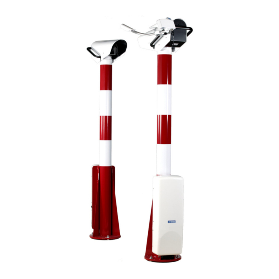
User's Guide ______________________________________________________________________ 0401-016 Figure 1 Vaisala Transmissometer LT31 The following numbers refer to Figure 1 above. LT31 receiver unit Receiver measurement head Mast Receiver interface unit LT31 transmitter unit PWD forward scatter sensor Transmitter measurement head Mast Transmitter interface unit Receiver Unit LTR111 is shown in Figure 2 on page 27 and Transmitter Unit LTT111 in Figure 3 on page 28. -
Page 27: Figure 2 Receiver Unit Ltr111 With Lm21 Background Luminance
Chapter 2 __________________________________________________________ Product Overview 1104-087 Figure 2 Receiver Unit LTR111 with LM21 Background Luminance Sensor VAISALA _______________________________________________________________________ 27... -
Page 28: Figure 3 Transmitter Unit Ltt111 With Pwd Forward Scatter Sensor
User's Guide ______________________________________________________________________ 1104-088 Figure 3 Transmitter Unit LTT111 with PWD Forward Scatter Sensor Both these units contain a similar mast construction with an inner and outer mast tube. The measurement unit of the transmitter and the receiver is mounted to the inner mast tube. All other parts of the measurement head are attached to the Support Unit which is mounted to the outer mast tube. -
Page 29: Figure 4 Measurement Head
Furthermore, a PWD forward scatter sensor is an integral part of the measurement system. This sensor is mounted to the measurement head of the LT31 transmitter unit. The LT31 transmitter unit consists of the following parts: - Mast - Transmitter interface unit including power supply and terminals... -
Page 30: Mast With Support Unit
All other parts are mounted to the outer mast tube. The frangibility of LT31 is achieved by using special mounting bolts equipped with a predetermined breaking point. All connection cables between the measurement head and the interface unit are routed between the inner and the outer mast tube. -
Page 31: Figure 5 Support Unit
Weather protection hood Mounting frame Outer mast tube The support unit is mounted to the outer mast tube of the LT31 mast construction. It consists of the mounting frame, weather protection hood, support arm, and blower. The only difference between the support unit of the LT31 transmitter unit and the LT31 receiver is that the support arm of the transmitter is equipped with a mounting flange for the PWD forward scatter sensor. -
Page 32: Measurement Unit
User's Guide ______________________________________________________________________ Measurement Unit The measurement unit (see Figure 6 below) consists of the following parts: - Measurement head enclosure with a cover and air duct - Window heater - Optics unit with - Measurement CPU board (including a window receiver) - Window transmitter module - Main transmitter module for the transmitter measurement head or main receiver module for the receiver measurement head... -
Page 33: Figure 7 Measurement Unit Opened
Chapter 2 __________________________________________________________ Product Overview 0401-023 Figure 7 Measurement Unit Opened The following numbers below refer to Figure 7 above. Window heater Window transmitter module Optics unit Optics tube Measurement CPU Mounting position for the main transmitter module Main receiver module VAISALA _______________________________________________________________________ 33... -
Page 34: Interface Unit
The interface unit contains all the needed terminals and power supply. In the LT31 receiver, the interface unit also contains the master CPU which controls the entire measurement system. If the battery backup option is installed, the related components are also located inside the interface unit. -
Page 35: Equipment Nomenclature
Chapter 2 __________________________________________________________ Product Overview Equipment Nomenclature Table 3 LT31 Transmissometer Nomenclature Code Common Name Description LTT111 Transmitter Unit LTM112 Measurement unit Enclosure with windows, heating, optics transmitter unit and air duct LTO112 Optics unit Incorporates optics tube, alignment transmitter... -
Page 36: Table 4 Lt31 Nomenclature For The Options
To be used when casting the screws foundation screws into new pads DMX501 Modem For remote communication (leased line) LM21LT Background Luminance LM21 sensor with LT31 specific support Sensor arm, mounting bracket and cable LTBB111 Battery Backup QBR101 battery charger and battery LT31OBS Obstruction Light... -
Page 37: Table 6 Lt31 Spare Parts For Options
Chapter 2 __________________________________________________________ Product Overview Table 6 LT31 Spare Parts for Options Code Common Name Description DMX501 Modem LM21F Background luminance Complete spare unit sensor LM21 spare Refer to LM21 User's Guide parts OBS24DSSP Obstruction light One spare unit TERMBOX-... - Page 38 User's Guide ______________________________________________________________________ This page intentionally left blank. 38 __________________________________________________________________ M210667EN-C...
-
Page 39: Functional Description
LT31. Operating Principles This section describes the basic principles behind the operation of the Vaisala Transmissometer LT31. The most direct and accurate method for assessing visibility is the measurement of transmittance. Vaisala Transmissometer LT31 directly measures the atmospheric transmission between the light transmitter and the light receiver. -
Page 40: Meteorological Optical Range
User's Guide ______________________________________________________________________ - As an operational parameter which corresponds to specific criteria for special applications. In this case, the concept of visibility is applied directly in terms of the distance of visibility. To simplify this problem and to enable quantitative physical measurement, the factors involved in estimating visibility distance can be separated as follows: - Photometric and dimensional characteristics of the object which are,... -
Page 41: Visibility Measurement
The calibration of a transmissometer is traditionally based on human observation. Vaisala Transmissometer LT31 does no longer need to be calibrated manually. LT31 uses an integrated forward scatter sensor of the Vaisala PWD series to fully calibrate the system automatically. VAISALA _______________________________________________________________________ 41... -
Page 42: Auto-Alignment
Furthermore, window dirt contamination has only a minor influence on the accuracy. The LT31 uses the auto-calibration method patented by Vaisala in order to utilize the advantages of the forward scatter sensor measurement principle to calibrate the transmissometer measurement. In practice the... -
Page 43: Alignment Quality Control
Chapter 3 ______________________________________________________ Functional Description as the receiver optics tube of the Vaisala Transmissometer LT31 are mounted in a cardanic frame so that the optics tube can be moved around the lens position. When the auto-alignment feature is activated, the optics tubes are... -
Page 44: Preventing Contamination
To a certain degree, the signal loss due to reduced alignment quality is compensated for by the auto-calibration mechanism. The status of the alignment quality evaluation is given in the frame of the LT31 serial data message and a realignment request is generated in case the alignment quality loss is too high. -
Page 45: Hardware Descriptions
CPU board. This principle is described in Figure 11 below. LT31 uses the measurement CPU board’s measurement for the following: - Measuring the real transparency of the windows. -
Page 46: Figure 12 Communication Principle
At least four of the intelligent units of the measurement system (master CPU, transmitter measurement CPU, receiver measurement CPU, PWD) are connected by the RS-485, the LT31 internal communication bus (called the module bus). Furthermore, the modulation clock of the main transmitter module is transmitted to the receiver measurement unit using RS-422 technology. -
Page 47: Measurement Unit Ltm112/212
- Transmitter optics unit (main transmitter module, window transmitter module, and measurement CPU board including window receiver) The measurement unit of the LT31 receiver unit is named LTM212 and consists of the following: - Measurement enclosure with cover and air duct... -
Page 48: Optics Unit Lto112/212
Mounting chassis with an alignment mechanism, optics tube and optics suspension Window transmitter module Measurement CPU (including window receiver) Main transmitter module The optics unit of the LT31 receiver is named LTO212 (see Figure 15 on page 49). 48 __________________________________________________________________ M210667EN-C... -
Page 49: Main Transmitter Module Ltl112
CPU using two connectors. The main transmitter module is shown in Figure 16 below. 1104-091 Figure 16 Main Transmitter Module LTL112 The main transmitter module contains a white, high-power LED as a light source and an optical diffuser foil for homogenous light distribution. VAISALA _______________________________________________________________________ 49... -
Page 50: Main Receiver Module Ltd112
User's Guide ______________________________________________________________________ Under the control of the measurement CPU, the light source is modulated with a frequency of approximately 1 kHz. A monitor photodiode measures the emitted light intensity and the main transmitter module uses a closed loop regulator in combination with a LED driver to achieve a normalized, constant transmitter intensity. -
Page 51: Figure 18 Main Receiver Module Ltd112
The main receiver module contains a temperature measurement and an EEPROM. These components are connected to the measurement CPU via the IIC-Bus interface. Individual calibration parameters are stored in the EEPROM and are used to adapt individual settings, especially after module exchange. VAISALA _______________________________________________________________________ 51... -
Page 52: Window Transmitter Module Ltl212
User's Guide ______________________________________________________________________ The basic principle of LTD112 is shown in Figure 19 below. Measurement Main Receiver DC Main Transmitter Main Transmitter Clock Detector Narrow Band Synchronous 20bit ADC Amplifier Demodulator Main Receiver Signal Test LED Test LED Temperature Measurement EEPROM 0401-036 Figure 19... -
Page 53: Measurement Head Cpu Ltc112
Measurement Head CPU LTC112 The measurement head CPU LTC112 (see Figure 22 below) is used for the optics unit of the LT31 transmitter and as well for the LT31 receiver. The hardware and software for transmitter and receiver are identical. The CPU detects automatically if it is active in an LT31 transmitter or receiver environment and selects the software configuration accordingly. - Page 54 User's Guide ______________________________________________________________________ - 80C552 CPU (including 8-channel 10-bit ADC) - RAM and Flash memory - 2-channel 20-bit ADC - EEPROM - RS-485 interface The functional units of the measurement head CPU LTC112 are the following: - Power supply - RS-485 module interface - Alignment unit control - Heater control - Piezo beeper...
-
Page 55: Interface Unit Lti111/211
The interface unit LTI111/211 (see Figure 24 on page 56) consists of the AC power supply (FSP102, transformer, and switch), master CPU LTC212 in the case of the receiver interface unit, and the optional backup battery LTBB111. VAISALA _______________________________________________________________________ 55... -
Page 56: Power Supply Fsp102
LTI111 provides an interface and power supply for the PWD Forward Scatter Sensor. The external power inputs and the communication interfaces of LT31 are located in the interface units. All external interfaces are equipped with surge protection circuitry. -
Page 57: Figure 25 Power Supply Fsp102
With higher level and repeated transient surges, the high surge current will blow the main fuses F1 and F2. The circuit board is thus protected against high surge currents and the unit is operational after fuses are replaced. VAISALA _______________________________________________________________________ 57... -
Page 58: Master Cpu Ltc212
Figure 26 Master CPU LTC212 The CPU module is equipped with: - H8 CPU - RAM & Flash memory - LT Maintenance Interface (RS-232) - Module interface (RS-485); to control the LT31 system and to collect raw data 58 __________________________________________________________________ M210667EN-C... -
Page 59: Present Weather Detector Forward Scatter Sensor
Present Weather Detector Forward Scatter Sensor A Present Weather Detector (PWD) forward scatter sensor (see Figure 27 below) is mounted to the support arm of the LT31 transmitter unit. It is used for auto-calibration and for present weather detection (optional). 0401-043... -
Page 60: Software Descriptions
- The measurement CPU of the transmitter - The measurement CPU of the receiver Master CPU The master CPU is located in the interface unit of the LT31 receiver limit. The main tasks of the master CPU are as follows:... -
Page 61: Optional Equipment Descriptions
RVR applications. The sensor is mounted to the LM21 support arm, which is attached to the mast construction of the LT31 receiver unit. The support arm can be rotated for coarse horizontal orientation of the LM21 while the mounting bracket allows fine horizontal and vertical alignment. -
Page 62: Termbox-1200/Termbox-9000
Surge protectors are available for the following signal line types: - Leased-line modem - RS-485 The TERMBOX -9000 (LT31 transmitter unit) offers surge protection for the AC power only. Obstruction Light LT31OBS The obstruction light is equipped with a mounting clamp (see Figure 29 on page 63). -
Page 63: Battery Backup Ltbb111
Battery Backup LTBB111 The optional battery backup LTBB111 (see Figure 30 on page 64) is installed in the interface units of LT31 transmitter and receiver unit. A proper and fully charged battery ensures operation for a period of approximately 60 minutes (at 20 C) if power failure occurs. -
Page 64: Figure 30 Installed Battery Charger Module Qbr101
User's Guide ______________________________________________________________________ 0401-041 Figure 30 Installed Battery Charger Module QBR101 The following numbers refer to Figure 30 above. Battery charger module QBR101 DC switch The battery is mounted below the master CPU cover and is part of LTI111 and LTI211. An installed backup battery is shown in Figure 31 on page 65. -
Page 65: Figure 31 Installed Backup Battery
The DC switch is used to interrupt the battery-based power supply for storage, transportation, and maintenance of the instrument. CAUTION Do not short circuit the battery. A valve-regulated lead battery is used for the battery backup. According NOTE to the ISO 14001, the battery must be recycled. VAISALA _______________________________________________________________________ 65... - Page 66 User's Guide ______________________________________________________________________ This page intentionally left blank. 66 __________________________________________________________________ M210667EN-C...
-
Page 67: Chapter 4 Installation
INSTALLATION This chapter provides you with information that is intended to help you install this product. If LT31 is equipped with enhanced weather protection hoods, follow the NOTE instructions given in the document LT31 Enhanced Weather Protection Hoods Installation Guide (see section Related Manuals on page 16). - Page 68 User's Guide ______________________________________________________________________ Select the location and perform site survey: - Check that the installation area is in accordance with the ICAO recommendations. - Check the ground level at the recommended safety distance of 120 m from the runway. It should have approximately runway surface level.
- Page 69 - Make intercommunication connections to the transmitter. - Connect the communication line to the host system. - Connect the AC voltage to the power supply of the interface unit. Perform startup tests, final alignment, and calibration for the LT31 system. VAISALA _______________________________________________________________________ 69...
-
Page 70: Selecting Location
LT31 must be sited according to the related ICAO requirements. - LT31 should be located at a distance of usually up to 120 m in parallel to the runway. - The recommended standard distance between LT31 transmitter and receiver is 30 m (50 m and 75 m are optionally possible). -
Page 71: Unpacking Procedure
Place the packing materials and covers back in the cases and store them for possible reshipment. Storage Store LT31 in its packages in dry conditions, not in the open air. The storage conditions are: - Temperature: -50 C to 70 C... -
Page 72: Equipment Grounding And Lightning Protection
User's Guide ______________________________________________________________________ NOTE If LT31 contains a battery backup option and if the unit is stored in an extremely cold environment, make sure that the battery is fully charged. Equipment Grounding and Lightning Protection The power supply cable with its protective earth conductor (PE) provides a standard protective ground for the AC power supply inside the interface unit. -
Page 73: Cable Selection
Cable Selection This section describes the power and signal cabling of LT31. The customer is responsible for supplying the power and signal cables, and conduits for the cables. In all field cabling, the following should be remembered: - Use armored field cables. -
Page 74: Line Power Cable
LT31 should be equipped with a power cable of sufficient length with free wire ends. If a local terminal with the power supply of 115/230 VAC is not available, an extended AC cable from LT31 to the nearest power source is needed. This cable should be armored and suitable for underground use. -
Page 75: Figure 33 Termbox-1200/Junction Box For Receiver
The distance between the equipment and the AC distribution transformer, and the power consumption of the equipment, dictate the thickness of the cable. The minimum requirement for the power cable is 3 x min 1.5 mm (AWG 15) 3-conductor power cable. VAISALA _______________________________________________________________________ 75... -
Page 76: Communication Cable
The signal cable shields should be grounded at both ends. For the intercommunication between the LT31 transmitter and receiver two screened 2 x 0.22 mm (approximately AWG 23) twisted pair signal cables with a shield and minimum diameter of 8 mm are recommended. -
Page 77: Figure 35 Cable Grounding Instruction
Communication Options on page 78. 0201-070 Figure 35 Cable Grounding Instruction The following number refers to Figure 35 above. = Cable shield NOTE Cables with diameters more than 15 mm require a separate junction box. Vaisala TERMBOX-1200/TERMBOX-9000 is recommended. VAISALA _______________________________________________________________________ 77... -
Page 78: Communication Options
RTS and CTS are not required but they can be used. The hardware flow control can be enabled in LT31. As a default, the RTS and CTS lines are not used. For details, see Chapter 5, Operation, on page 145. -
Page 79: Serial Multipoint Transmission With Rs-485
CPU board. See Figure 37 on page 80. NOTE The cable shield of RS-485 cable must be properly grounded in the cable gland of interface enclosure, see Figure 35 on page 77. VAISALA _______________________________________________________________________ 79... -
Page 80: Figure 37 Rs-485 Communication Option
RS-485 Communication Option Terminate the RS-485 chain with a 120 resistor. This is especially important with long cables. If LT31 is at the end of the RS-485 chain, the 120 resistor can be connected across the screw terminal pins. The 120 ... -
Page 81: Modem Dmx501 (Optional)
CCITT standards, as well as the DMX50 and DMX55 modems for the Vaisala MILOS500, can be used with the DMX501 modem. If the modem is installed (LT31 was ordered with the modem option), connect the incoming signal wires to the MOD3 and MOD4 screw terminals 25 and 26 at the CPU board LTC212. -
Page 82: Figure 39 Modem Wiring
User's Guide ______________________________________________________________________ Reset Status Reset Button +12V Out Sensor line RS-485+ RS-485- Data line RS-232 Data RS-485+ line RS-485- Maint. line MILOS 500 or other RS-232 host computer MOD1 Module Modem MOD2 Modem connection (modem) MOD3 (modem) MOD4 MOD5 0401-070 Figure 39 Modem Wiring... -
Page 83: Figure 40 Ac And Battery Backup Switch
Open the two screws holding the LTC212 board in place and withdraw the board carefully. Remove the DMX501 modem module from its protective package and install it by pressing it gently into the module place of the LTC212 board (see Figure 41 on page 84). VAISALA _______________________________________________________________________ 83... -
Page 84: Figure 41 Installing Dmx501
User's Guide ______________________________________________________________________ 0201-071 Figure 41 Installing DMX501 The following number refers to Figure 41 above. = DMX501 Modem module NOTE Handle the boards carefully. Do not touch the components on the boards to avoid ESD damage to them. Ground yourself before attempting to touch the boards. -
Page 85: Multipoint Modem Connection
In case this recommendation cannot be followed due to the runway setup that dictates an LT31 orientation where sunlight can unavoidably enter one of the LT31 measurement units for a few days of the year during sunrise or sunset, it is recommended that the LT31 receiver unit LTR111 is installed pointing towards the low sun. -
Page 86: Foundation
Figure 42 below. This size generates sufficient space to place a ladder safely near the transmissometer transmitter and receiver. The distance between foundation centers should meet the desired baseline length plus 0.5 m for LT31 (typically 30 m + 0.5 m). 0401-054... -
Page 87: Dowel Mounting
See Figure 42 on page 86. Dowel mounting The optional foundation kit (LTMK111) for LT31 dowel mounting contains the required equipment for mounting to an existing surface. The triangle-shaped drilling template should be used to set the drilling holes as precisely as possible. -
Page 88: Figure 43 Positioning Drilling Holes
User's Guide ______________________________________________________________________ 0401-068 Figure 43 Positioning Drilling Holes Drill three 20 mm holes with a depth of 70 mm using the drilling template. Check carefully that the holes are drilled perfectly perpendicular. Remove the template. Clean the holes. Insert the dowels into the holes and hammer them down until their edges are on the foundation level. -
Page 89: Molded Screw Mounting
80 Nm). Check using the drilling template that the screw positions fit. Molded Screw Mounting The optional foundation kit for LT31 molded screw mounting contains the required equipment for foundation screw insertion into the wet concrete. Foundation construction is shown in Figure 45 on page 91. To mount the... - Page 90 Embed the assembly in the concrete foundation as shown in Figure 45 on page 91. Be sure to align the assembly taking the optical axis of LT31 into account as shown in the figure (orientate the assembly in such a manner, that one of the foundation screws points exactly towards the opposite installation place).
-
Page 91: Figure 45 Lt31 Foundation Construction
Chapter 4 _______________________________________________________________ Installation 0906-095 Figure 45 LT31 Foundation Construction The following numbers and letter refer to Figure 45 above: 1 = Drilling template 2 = Foundation screw 3 = Reinforcing plate A = Direction of optical axis of LT31 VAISALA _______________________________________________________________________ 91... -
Page 92: Preparing Assembly Of Lt31
Vaisala Transmissometer LT31 is delivered in a disassembled state to protect the parts during transportation. To assemble and install LT31 on site in the most efficient way, follow the steps below. If the instruments parts are already unpacked, transport them carefully to their installation places. -
Page 93: Figure 46 Receiver Installation Parts
- Junction box with enhanced overvoltage protection for signal and AC lines (type TERMBOX-1200). - Obstruction Light (type LT31OBS) . - Enhanced weather protection hood (for details, refer to LT31 Enhanced Weather Protection Hoods Installation Guide in section Related Manuals on page 16) -
Page 94: Setting Up Receiver Mast To Foundation
User's Guide ______________________________________________________________________ Setting up Receiver Mast to Foundation Screw one nut on the three foundation screws (see Figure 47 below), until the distance between the foundation surface and the nut top is 5 cm. Place a washer on top of the nuts. 0401-049 Figure 47 Foundation Screws... -
Page 95: Setting Up Weather Protection Hood To Support Unit
Weather Protection Hoods Installation Guide in section Related Manuals on page 16. Both hood types have identical mechanical fixtures. When LT31 is ordered with heated hoods, the PWD forward scatter sensor is also equipped with hood heating. In this case, the heating power... -
Page 96: Figure 50 Mounting Weather Protection Hood
User's Guide ______________________________________________________________________ To set up the weather protection unit: Place the ladder in front of the receiver mast. Then install the weather protection hood. Fix the hoods with two screws (hex socket head, size 3) at each rear end corner of the hood. See Figure 50 below. 0401-073 Figure 50 Mounting Weather Protection Hood... -
Page 97: Figure 52 Fastening Screws Of Support Unit
Fastening Screws of Support Unit Align the support unit horizontally to the position where the transmitter mast will be located in the future. Use the sight hole in the rear plate together with the sight. See Figure 53 on page 98. VAISALA _______________________________________________________________________ 97... -
Page 98: Mounting Optional Lm21
Mounting Optional LM21 Background Luminance Sensor LM21 is provided together with LM21 cable, support arm and mounting bracket for attachment to the LT31 receiver mast. The Figure 54 on page 99 shows the LT31 with installed LM21 option. 98 __________________________________________________________________ M210667EN-C... -
Page 99: Figure 54 Lt31 With Lm21 Option Installed
Chapter 4 _______________________________________________________________ Installation 1104-096 Figure 54 LT31 with LM21 Option Installed The following numbers refer to Figure 54 above. Transmissometer LT31 Background Luminance Sensor LM21F Mounting bracket Support arm Fastener assembly To install the optional LM21 proceed as follows:... -
Page 100: Figure 55 Routing Lm21 Cable Through Mounting Bracket
User's Guide ______________________________________________________________________ 1104-097 Figure 55 Routing LM21 Cable through Mounting Bracket The following numbers refer to Figure 55 above. Rotation plate of the mounting bracket Connector of LM21 cable Insert the LM21 support arm into the guide which is located behind the interface unit. -
Page 101: Figure 57 Installing Lm21 To Mounting Bracket And Attaching Connector
M5x25 DIN912 (which are part of the delivery) and the fastener assembly according to Figure 58 on page 102 using a hex socket wrench (size 4). NOTE Ensure that the LM21 cable is not pinched during this procedure. VAISALA ______________________________________________________________________ 101... -
Page 102: Figure 58 Mounting Lm21 To Support Arm
User's Guide ______________________________________________________________________ 1104-100 Figure 58 Mounting LM21 to Support Arm The following numbers refer to Figure 58 above. LM21 Support arm LM21 fastening screws Fastener assembly Mounting bracket Carry out the horizontal alignment of the LM21. 102 _________________________________________________________________ M210667EN-C... -
Page 103: Figure 59 Coarse Horizontal Lm21 Alignment
Coarse Horizontal LM21 Alignment o Secure the support arm in its final position with the respective hex socket size 4 screw located slightly above the interface unit. See Figure 60 below. 1104-102 Figure 60 Securing Support Arm VAISALA ______________________________________________________________________ 103... -
Page 104: Figure 61 Lm21 Fine Horizontal Alignment
User's Guide ______________________________________________________________________ o Horizontal fine alignment is done using the rotation plate of the mounting bracket. Loosen the two hex socket size 4 screws of the rotation plate, rotate the LM21 as intended and tighten the rotation plate screws afterwards. See Figure 61 below. 1104-103 Figure 61 LM21 Fine Horizontal Alignment... - Page 105 Slightly loosen all four vertical alignment screws of the mounting bracket using a hex socket wrench size 4. Adjust the vertical alignment of the LM21 as intended and tighten all four vertical alignment screws of the mounting bracket. See Figure 62 on page 106. VAISALA ______________________________________________________________________ 105...
-
Page 106: Figure 62 Lm21 Vertical Alignment
User's Guide ______________________________________________________________________ 1104-104 Figure 62 LM21 Vertical Alignment The following numbers refer to Figure 62 above. Mounting bracket Vertical alignment screws Open the interface unit box. Figure 63 on page 107. 106 _________________________________________________________________ M210667EN-C... -
Page 107: Figure 63 Opening Interface Unit Box
Tighten the cable gland carefully and wind the rest of the cable into a ring. Secure it with standard cable tabs. NOTE LT31 must be powered down when connecting LM21 The cable connections have to be done according to Figure 64 on page 108. -
Page 108: Figure 64 Wiring Of Lm21 To Receiver Interface Unit
User's Guide ______________________________________________________________________ 1104-105 Figure 64 Wiring of LM21 to Receiver Interface Unit The following numbers refer to Figure 64 above. Pink wire – connected to Master CPU pin 9 Gray wire – connected to Master CPU pin 10 Green wire – connected to Master CPU pin 11 Yellow wire –... -
Page 109: On-Site Transmitter Installation
- Junction box with enhanced overvoltage protection for signal and AC lines (type TERMBOX-9000) - Obstruction Light (type LT31OBS) - Enhanced weather protection hood (for details, refer to LT31 Enhanced Weather Protection Hoods Installation Guide in section Related Manuals on page 16) -
Page 110: Setting Up Transmitter Mast To Foundation
User's Guide ______________________________________________________________________ Setting up Transmitter Mast to Foundation To set up the transmitter mast to the foundation, do the following: Screw one nut each on the three foundation screws until the distance between the foundation surface and the nut top is 5 cm. Place a washer on top of the nuts. -
Page 111: Foundation Level Differences
Move the mast by turning the nuts above and below the base plate on the front foundation screw. See Figure 66 below. 0401-088 Figure 66 Front Nut Adjustment to Tilt Mast VAISALA ______________________________________________________________________ 111... -
Page 112: Mounting Optional Obstruction Light Lt31Obs
User's Guide ______________________________________________________________________ NOTE The two other securing nuts have to be loose enough to allow the slight movement of the base plate. After this alignment is finished, the foundation nuts must be fixed as tight as possible to allow for a safe positioning of the mast. A torque of 60 …... -
Page 113: Figure 68 Mounting Lt31Obs
See Figure 69 below. 0401-090 Figure 69 Cable Routing of LT31OBS Canalize the cable end through the cable hole in the outer mast tube below the interface unit box. See Figure 70 on page 114. VAISALA ______________________________________________________________________ 113... -
Page 114: Mounting Transmitter Measurement Unit
User's Guide ______________________________________________________________________ 0401-091 Figure 70 Cable Hole below Interface Unit Fix the cable to the cable comb inside the support unit using standard cable tabs. See Figure 71 below. 0401-092 Figure 71 Cable Comb for Securing LT31OBS Cable Open the interface unit box. See Figure 63 on page 107. Wire the cable through one cable feed-through at the bottom of the box. -
Page 115: Figure 72 Measurement Unit Cover Screws
Place the ladder to the side of the transmitter mast and select the side where the weather protection hood points left. Loosen the two fastening screws at the side of the measurement unit flange (hex-socket, size 4). See Figure 74 on page 116. VAISALA ______________________________________________________________________ 115... -
Page 116: Figure 74 Fastening Screws Of Measurement Unit
User's Guide ______________________________________________________________________ 0808-004 Figure 74 Fastening Screws of Measurement Unit Place the measurement unit on top of the inner mast tube (windows pointing left). Do not use the air duct on top of the unit as a handle, carry the measurement unit at the enclosure sides! The connection cable must be routed below the small junction box near the blower. -
Page 117: Figure 76 Parallel Position Of Measurement Unit
Place the ladder behind the transmitter and check the parallel position again. Then tighten the fastening screws (hex-socket, size 4) on the right side of the measurement unit which are now accessible through the mast adapter of the support unit. See Figure 78 on page 118. VAISALA ______________________________________________________________________ 117... -
Page 118: Mounting Pwd To Support Arm
User's Guide ______________________________________________________________________ 0401-085 Figure 78 Fastening Measurement Unit Mounting PWD to Support Arm The “ear” on the support arm is foreseen for the mounting of the PWD Forward Scatter Sensor. See Figure 79 below. 0401-098 Figure 79 Mounting PWD Use two hex-socket screws size 5 with washers to mount the PWD Forward Scatter Sensor to the support arm. -
Page 119: Connecting Signal Lines To Transmitter Interface Unit
The interface unit of the transmitter must be connected to the two-wire RS-485 module bus (terminals 8 and 10) which connects all intelligent modules within the LT31 system with each other. In addition, a two-wire synchronization line (terminals 6 and 7) connects the modulation clock between the transmitter and receiver. -
Page 120: Figure 81 Transmitter Unit Ltt111 Wiring
User's Guide ______________________________________________________________________ 1104-106 Figure 81 Transmitter Unit LTT111 Wiring Tighten the cable feed-through carefully, wind the rest of the cable length to a ring and secure it with standard cable tabs. For details, see section Communication Cable on page 76. 120 _________________________________________________________________ M210667EN-C... -
Page 121: Mounting And Connecting Optional Termbox-9000 (Junction Box)
CAUTION Double-check that the AC power is switched off. No voltage must be detected at the end of the underground power cable. Route the underground cable through a fitting cable feed-through and connect the power lines carefully. VAISALA ______________________________________________________________________ 121... -
Page 122: Connecting Power Cable To Transmitter Interface Unit
Tighten the cable feed-through carefully and close the cover plate. Connecting Power Cable to Transmitter Interface Unit The power cable should be either connected into the Vaisala TERMBOX-9000, see section Mounting and Connecting Optional TERMBOX-9000 (Junction Box) on page 121 or routed straight through the opening in the base plate of the mast and further into a local power distribution box. -
Page 123: Finalizing On-Site Receiver Assembly
After this alignment is finished, the foundation nuts must be fixed as tight as possible to allow for a safe positioning of the mast. A torque of 60 … 80 Nm is recommended. VAISALA ______________________________________________________________________ 123... -
Page 124: Mounting Optional Obstruction Light Lt31Obs
User's Guide ______________________________________________________________________ Mounting Optional Obstruction Light LT31OBS Place the ladder behind the receiver mast. Then follow the instructions in section Mounting Optional Obstruction Light LT31OBS on page 112. Mounting Receiver Measurement Unit Before the measurement unit can be installed, the transportation lock for CAUTION the optics unit must be removed! Open the measurement unit carefully. -
Page 125: Connecting Signal Lines To Receiver Interface Unit
The receiver interface unit must be connected to the two-wire RS-485 module bus (terminals 8 and 10) which connects all intelligent modules within the LT31 system with each other. In addition, a two-wire synchronization line (terminals 6 and 7) connects the modulation clock between transmitter and receiver. -
Page 126: Figure 84 Receiver Unit Ltr111 Wiring
User's Guide ______________________________________________________________________ 1104-107 Figure 84 Receiver Unit LTR111 Wiring 126 _________________________________________________________________ M210667EN-C... -
Page 127: Mounting And Connecting Optional Termbox-1200 (Junction Box)
Tighten the cable feed-through carefully and close the cover plate. The receiver interface unit is equipped with the master CPU LTC212. This CPU is responsible for communication with all intelligent units within the LT31 system and for the communication with the host VAISALA ______________________________________________________________________ 127... -
Page 128: Connecting Communication And Power Cables
The receiver interface unit is equipped with the master CPU LTC212. This CPU is responsible for communication with all intelligent units within the LT31 system and for the communication with the host computer system. Connect the respective data terminals of the interface unit with the recommended communication cable type, see section Cable Selection on page 73. -
Page 129: Figure 85 Power Supply Switches
Chapter 4 _______________________________________________________________ Installation 0401-146 Figure 85 Power Supply Switches 0808-005 Figure 86 Power Supply LEDs The green LED on the master CPU LTC212 inside the interface unit of the receiver must flash. See Figure 87 on page 130. VAISALA ______________________________________________________________________ 129... -
Page 130: Figure 87 Master Cpu Ltc212 Leds
User's Guide ______________________________________________________________________ 0806-038 Figure 87 Master CPU LTC212 LEDs 130 _________________________________________________________________ M210667EN-C... -
Page 131: Double-Checking Transmitter Alignment
Chapter 4 _______________________________________________________________ Installation The LEDs behind the right window of the measurement units of LT31 transmitter and receiver must flash. See Figure 88 below. 0401-123 Figure 88 Measurement Unit LEDs At transmitter location, the white transmitter light must be observable through the left window. -
Page 132: Startup Procedure
LT31. The maintenance cable QMZ101 (included in the delivery) provides a 9-pin D connector for the computer and a connector for LT31. The external maintenance connector of LT31 is located at the right side of the receiver interface unit (see Figure 89 below). -
Page 133: Figure 90 Lt Maintenance Interface
Figure 90 LT Maintenance Interface The maintenance cable for Vaisala MILOS 500 can also be used, but in this case the door of the receiver interface unit LTI211 must be opened and the original maintenance line connector in the LTC212 board disconnected (see Figure 91 on page 134). -
Page 134: Settings For Maintenance Terminal
Entering and Exiting Command Mode Before any commands can be given to LT31, the maintenance or data line of LT31 has to be assigned to the operator. Otherwise, it is assigned to automatic messages or polled communication. 134 _________________________________________________________________ M210667EN-C... -
Page 135: Open Command
If no ID is configured, the LT31 sensor answers as follows: 0> LT31 line opened for operator commands If no input is given within 10 minutes (default), LT31 closes the line automatically and gives the following answer: LT31 line closed... -
Page 136: Figure 92 Main Menu
(RS-485/Modem), LT31 must be used in the polled mode and the individual sensors must have distinct identifiers (ID). You can check/set the basic configuration parameters of the LT31 in an easy way. Select the maintenance menu by first typing the OPEN command as explained above and then the MENU command. -
Page 137: Figure 93 Configuration Menu
Operation on page 145. Note the following remarks: - The Identifier parameter is * only if one LT31 is connected on the data line and no ID is needed. - The Baseline parameter must be set according to the real installation situation. -
Page 138: Checking Operation
To exit the MENU pages, press ESC. NOTE Checking Operation Pressing B on the keyboard on the MAIN MENU page gives access to the LT31 System Status page (see Figure 94 below). 0401-131 Figure 94 System Status TRANSMITTER must indicate OK in all positions. -
Page 139: Final Alignment
Transmissometer into a final operational condition. This process is carried out in the frame of the LT31 Calibration. The LT31 Calibration Procedure is menu-guided. CAUTION Calibration must be carried out at this point of the LT31 installation. -
Page 140: Finalizing Installation
After all the installation steps have been proceeded and the fine- alignment as well as the calibration have been carried out successfully, the LT31 system can be finally prepared for operational use. When the fastening screws for support units and measurement units are carefully fixed, the measurement head covers can be installed to LT31 receiver and transmitter. -
Page 141: Figure 97 Using Lock Screws At Measurement Head Cover
(see Figure 97 c below). 0906-096 Figure 97 Using Lock Screws at Measurement Head Cover VAISALA ______________________________________________________________________ 141... -
Page 142: Closing Interface Units
User's Guide ______________________________________________________________________ To remove the measurement head cover, follow these instructions: Loosen the fastening screws carefully by a quarter counterclockwise turn. Due to the included ejector the lock screws will easily slide out from the associated receptacle. The measurement head cover has to be lifted up before it can be removed from the support unit. -
Page 143: Figure 99 Lower Interface Unit Cover
Then press the upper cover part carefully against the mast construction. The whole cover is now in the final locked position. Tighten the screws on both sides of the lower part of the unit cover. See Figure 101 on page 144. VAISALA ______________________________________________________________________ 143... -
Page 144: Disassembly For Transportation
Upper Interface Unit Cover Disassembly for Transportation If the LT31 system or a single LT31 transmitter or receiver has to be transported to a different location, the instrument has to be disassembled to the same degree as during delivery and shipment. -
Page 145: Chapter 5 Operation
ENTER. Entering and Exiting Command Mode Before any commands can be given to LT31, the maintenance or data line of LT31 has to be assigned to the operator. Otherwise, it is assigned to automatic messages or polled communication. OPEN Command You enter the command mode with the OPEN command. - Page 146 An ID is not needed if the device type LT is included in the OPEN command. This device type can be used when there is only one LT31 on the line. This command is similar to the OPEN * command with the exception that it only opens the LT31 command mode and not the other possible sensors on the line.
-
Page 147: Close Command
The line can be released to automatic data messages with the CLOSE command. Type the following: 0> CLOSE The LT31 sensor with the ID 1 answers as follows: LT31-1 LINE CLOSED Available Commands With the HELP command the operator can get information about the available commands. -
Page 148: Table 10 User Level Commands
The password can be given as a parameter. If it is not given as a parameter, the user is asked for it. LEVEL 1 [password] The default password for the advanced level is LT31 (case sensitive). MEAS_SYNC Resets the measurement sequence. The following data message is measured starting from the moment all the average values are erased. - Page 149 SET MESSAGE TYPE FD12MSG2 Selects the FD12 message 2 emulation mode. The data message, message frames, and polling format are the same as they are in Vaisala FD12 Visibility Meter. SET MESSAGE TYPE FD12MSG7 Selects the FD12P message 7 emulation mode. The data message, message frames, and polling format are the same as they are in Vaisala FD12P Weather Sensor.
-
Page 150: Table 11 Advanced Level Commands
The time is given also in elapsed years, months, days, hours, minutes and seconds up to now. To access the advanced level, type (default LEVEL LEVEL 1 password 1 password: LT31). The password is case sensitive. Table 11 Advanced Level Commands Command Description... - Page 151 Enables background luminance sensor LM21 data polling in the LT31 system. SET LM OFF Disables background luminance sensor LM21 data polling and photo switch reading in the LT31 system (default). SET CONTAMINATION_COMPENSATION Disables the compensation function of LM21. LM OFF...
- Page 152 SET MESSAGE SECOND TYPE MITRAS Selects the MITRAS Single Base emulation mode for the Second Message. The data message and message frames are the same as they are in Vaisala MITRAS Transmissometer. SET MESSAGE SECOND TYPE Selects the FD12 message 2 emulation mode for the FD12MSG2 Second Message.
-
Page 153: Terminal Line Adjustment
This feature can be used in the host system, for example, for making automatic status message inquiries of active warnings or alarms. The general command polling format (with 1 as the unit ID) is the following: !LT1"&DO_COMMAND-#CSUM$-* VAISALA ______________________________________________________________________ 153... - Page 154 Line feed The response for the command is framed similarly, see below: !LT1"LT31-RESPONSE#CSUM$-* where Start of heading Start of text " LT31- Response of LT31 RESPONSE End of text CSUM Checksum End of transmission Carriage return Line feed For instance, the following command !!LT1"&DO_STATUS-#3D64$-*...
-
Page 155: Crc16 Checksum
The CRC16 checksum can be calculated using the following algorithm written in the programming language C: /* 16 bit type */ typedef unsigned short Word16; /* Calculate CRC-16 value as used in LT31 protocol */ Word16 crc16(const unsigned char *buf, int len) Word16 crc;... -
Page 156: Menu-Driven Operation
The menu-driven operation is designed for VT100 terminal with 80 columns. For proper operation, the terminal height in lines used by the terminal application must be configured to LT31 with the command SET TERMINAL_LINES number (minimum 24). In addition, any 'line wrap'- and 'translate CR or CR/LF'-option must be switched off for the terminal application in use. -
Page 157: Submenus
Configure data port mode (analog to SET DATA_PORT MODE) Configure data port format (analog to SET DATA_PORT PARITY) Configure modem (analog to SET MODULE MODEM) Selecting any of the above items will open either an item list or free-form input. VAISALA ______________________________________________________________________ 157... -
Page 158: Item List
0 for disabling automatic message interval (polled mode). 0401-129 Figure 105 Configuration Message Interval System Status The System Status menu (see Figure 106 on page 159) gives the possibility to have a quick overview into the entire LT31 system. All 158 _________________________________________________________________ M210667EN-C... -
Page 159: Alignment
The Linearity Test menu supports the user in performing a linearity test. For details, see section Linearity Test on page 245. Simulation The Simulation menu offers the definition of simulation sequences. For details, see section Simulation Sequences on page 189. VAISALA ______________________________________________________________________ 159... -
Page 160: Pwd Sensor
User's Guide ______________________________________________________________________ PWD Sensor The PWD Sensor menu offers a subset of PWD sensor commands. The commands can be executed through the LT31 maintenance terminal connection. For details, see section PWD Sensor on page 253. Service The Service menu offers an in depth view to the transmitter and receiver units. -
Page 161: Message Formats
A9:Alignment... The event text describes the event Message Formats In the command mode (entered with the OPEN command), the LT31 messages can be displayed using the MESSAGE command. In the independent mode (entered with the command CLOSE), LT31 can be... -
Page 162: Message Command
The polling request can ask for the automatic (default) or some other message (with a message number). When used as a part of an existing RVR system, LT31 can emulate the messages of Vaisala MITRAS Transmissometer, FD12 Visibility Meter, and Impulsphysik SKOPOGRAPH II Flamingo. - Page 163 Start of the text (ASCII 2). " VIS 10000.0 MOR value, unit m, 1-min-average. AL 00000000000000000000 Alarm status of the LT31 system (see Table 13 on page 164). BL 01000 Background luminance identifier and BL value, unit, cd m...
-
Page 164: Status Codes
LT31 window contamination LT31 alignment LT31 reserved for future extension LT31 reserved for future extension LT31 transmitter status LT31 transmitter -> main transmitter module LT31 transmitter -> window transmitter module LT31 transmitter -> measurement CPU LT31 transmitter -> misc. LT31 receiver status LT31 receiver ->... -
Page 165: Table 15 Lt31 Mor Status (Byte Number 22)
To enable the use of PWD MOR in error situations (default) use the command set pwd_mor_on_error on. The response is PWD MOR is used on error. Table 15 LT31 MOR Status (Byte Number 22) Code Explanation Comment Underrange MOR below measurement range limit. -
Page 166: Table 16 Lt31 Power Supply (Byte Number 23)
Table 16 LT31 Power Supply (Byte Number 23) Code Explanation Comment Battery mode No AC power. LT31 is working on a backup battery. Low backup No AC power. battery LT31 is working on a backup battery. voltage LT31 will shut... -
Page 167: Table 19 Lt31 Alignment (Byte Number 26)
3 Error Alignment procedure failed or alignment hardware error. Table 20 LT31 Future Extension 1 (Byte Number 27) Code Explanation Comment Table 21 LT31 Future Extension 2 (Byte Number 28) Code Explanation Comment The byte shown in Table 22 on page 168 indicates the overall status of the LTT111 (LT31 transmitter unit). -
Page 168: Table 22 Lt31 Transmitter Status (Byte Number 29)
The byte shown in Table 23 below indicates the status of the main transmitter module LTL112 which is located in the transmitter measurement unit LTM112 of the LTT111 (LT31 transmitter). Table 23 LT31 Transmitter: Main Transmitter Module (Byte Number 30) -
Page 169: Table 24 Lt31 Transmitter: Window Transmitter Module (Byte Number 31)
3. The byte shown in Table 25 below indicates the status of the measurement CPU LTC112 which is located in the transmitter measurement unit LTM112 of the LTT111 (LT31 transmitter). Table 25 LT31 Transmitter: Measurement CPU (Byte Number... -
Page 170: Table 26 Lt31 Transmitter: Miscellaneous (Byte Number 33)
Communication Device not responding on module error bus request. The byte shown in Table 28 below indicates the status of the LT31 master CPU LTC212 which is located in the receiver interface unit LTI211. Table 28 LT31 Receiver: Master CPU Status (Byte Number 35) -
Page 171: Table 29 Lt31 Receiver: Main Receiver Module (Byte Number 36)
If, for example, code 1 and code 2 occur at the same time, it will lead to code 3. The byte shown in Table 29 below indicates the status of the LT31 main receiver module LTD112 which is located inside the receiver measurement unit LTM212. -
Page 172: Table 31 Lt31 Receiver: Measurement Cpu (Byte Number 38)
If, for example, code 1 and code 2 occur at the same time, it will lead to code 3. The byte shown in Table 31 below indicates the status of the LT31 measurement CPU LTC112 which is located inside the receiver measurement unit LTM212. -
Page 173: Table 33 Lt31 Pwd Status (Byte Number 40)
Chapter 5 ________________________________________________________________ Operation The byte shown in Table 33 below indicates the status of the PWD forward scatter sensor which is mounted to the transmitter support unit LTS111 of the LTT111 (LT31 transmitter). Table 33 LT31 PWD Status (Byte Number 40) -
Page 174: Message 2 - Lt31 Message Including Pw Data (Optional)
Start of the text (ASCII 2) " VIS 10000.0 MOR value, unit m, 1-min-average AL 00000000000000000000 Alarm status of the LT31 system (see Table 13 on page 164) BL 01000 Background luminance identifier and BL value, unit, cd m... -
Page 175: Message 3 - Status Message
EEPROM:00 TEMP:00 ALIGN:00 MISC:00 HEATER:H BLOW:0 REC:S Temperatures (unit C): Heater:+51.0 Enclosure:+41.4 WinRec:+41.9 WinTrm:+43.2 MainRec:+37.9 PWD Sensor: OK PWD STATUS VAISALA PWD21 V 1.01 2001-11-01 SN:W42106 ID STRING: 0 SIGNAL 0.53 OFFSET 160.77 DRIFT 7.52 REC. BACKSCATTER CHANGE TR. BACKSCATTER -1.2... -
Page 176: Message 4 - Vaisala System Standard Message
4 s at 2400 bps, 1 s at 9600 bps. Message 4 - Vaisala System Standard Message Message 4 is defined according to the Vaisala system standard format. All units in the message are SI units. The message format is as follows: !LT1"VIS(02000(AL(0)))BL(00100(AL(0)))#CSUM$-*... -
Page 177: Message 5 And 6 - Fd12 Emulation
9600 bps. Message 5 and 6 - FD12 Emulation For compatibility in the system level, LT31 also supports the message format, frames, and polling format of Vaisala Visibility Meter FD12. The FD12 polling format is accepted only when the FD12 message emulation is selected. -
Page 178: Message 6 - Fd12 Message 7
Table 11 on page 150). If no valid keyword has been entered, the present weather values are replaced by a slash / (ASCII 47). The message format of the emulated Vaisala FD12 message number 7 is presented below: Message with framing: A"00 10000 10000... -
Page 179: Message 7 - Mitras Emulation
Chapter 5 ________________________________________________________________ Operation Message 7 - MITRAS Emulation For compatibility on the system level, LT31 also supports the message format, frames, and polling format of Vaisala MITRAS Transmissometer. The MITRAS polling format is accepted only when the MITRAS message emulation is selected with the SET MESSAGE TYPE MITRAS command. -
Page 180: Message 8 - Flamingo Emulation
In other words, Background Luminance Sensor LM21 is set as the background luminance sensor. Message 8 - Flamingo Emulation For compatibility in the system level, LT31 also supports the message format, frames, and polling format of Impulsphysik transmissometer SKOPOGRAPH II “Flamingo”. The FLAMINGO polling format is accepted only when the FLAMINGO message emulation is selected. -
Page 181: Message 9 - Service Raw Values
Message Sending Modes Automatic Mode In the automatic mode the LT31 system sends a predefined message at selected intervals. The automatic and default polled message can be defined with the SET MESSAGE TYPE command. For available messages, see section Message Formats on page 161. The format of the... -
Page 182: Polled Mode
SET MESSAGE INTERVAL 0 Polled Mode In the polled mode the LT31 system sends a data message when the host computer transmits a polling command. The automatic message sending mode is disabled by setting the message interval to zero with the... -
Page 183: Metar Messaging
Turning on the carrier will cause extra characters to be added in front of the ! character. The LT31 system waits for about 100 ms after the carrier has been turned on before it sends the message. When LT31 has sent the message, it turns the carrier off causing another set of extra characters that will also have to be ignored by the host. -
Page 184: System Configuration
User's Guide ______________________________________________________________________ Original LT31 messages from 1 to 9 are unchanged. The visibility data of PWD22 message 7 (one minute and ten minutes averages) is invalidated by slashes. The unit identifier given in the PWD22 message 7 is the same as set for LT31 unit identifier. -
Page 185: Default Factory Settings
Chapter 5 ________________________________________________________________ Operation The output is the following: LT31 parameter values: identifier: name: header: base length: command terminal: lines: timeout: message: type: interval: port: data frame: simulation: data port: speed: 9600 mode: rs-485 data format: 2nd port: none 2nd type:... -
Page 186: External Sensors (Optional)
Background Luminance Sensor LM21 The SET LM ON configuration command is used to add the LM21 sensor output into the LT31 system and the data messages. With this command, the interface unit CPU starts polling the LM21 sensor via the internal RS-485 sensor interface. -
Page 187: Fixed Test Messages
1850.0 AL 00000000000000000000 BL 00671 AL 0 WMO !LT1"VIS 00 WMO15M 00 WMO60M 00 RN1M 0.00 RNSUM 0.00 SNSUM 23.3 AL 0#24CE$-* Message 4 !LT1"VIS(01850(AL(0)))BL(00671(AL(0)))#9063$-* Message 5 - FD12 Message 2 Emulation 1"00 1850 2000 //// // /////#-* VAISALA ______________________________________________________________________ 187... -
Page 188: Message 6 - Fd12 Message 7 Emulation
MANUAL_MESSAGE command in the following way: SIMULATE MANUAL_MESSAGE string The LT31 sensor does not make any validity checks to the message body content which means that the message is transmitted as it is written. Special characters can be added to the message by using the following... -
Page 189: Simulation Sequences
(J). In the Info Area, the user can accept or modify each set of data. If the current data is kept, ENTER has to be pressed. Entering 0 (zero) for a visibility or background luminance value will lead to an indication of an appropriate value (slashes will be transmitted instead). VAISALA ______________________________________________________________________ 189... -
Page 190: Figure 110 Summary Of Sequence Data
User's Guide ______________________________________________________________________ The following is an example of modifying sequence A: Sequence (A) Duration In Seconds: [0] Typing will change the duration to 300 s. 300<CR> Sequence (A) VIS In m: [5000.0] Typing will change the visibility data to 8000 m. 8000<CR>... -
Page 191: Message 1
If simulation sequences are enabled for all messages, the value for MOR, status, and background luminance are replaced by sequence data. The LT31 sensor does not make any validity checks to the sequence data contents. As all messages do not have the capability to give all the defined data, some message formats use only parts of the defined sequence data. - Page 192 User's Guide ______________________________________________________________________ Flags for MOR and background luminance overrange are replaced by the first two characters of the overall status. Other characters of the overall status are omitted. As Skopograph II Flamingo does not indicate invalid values, minimum values are given when the invalid values have been set. 192 _________________________________________________________________ M210667EN-C...
-
Page 193: Chapter 6 Maintenance
This chapter provides information that is needed in basic maintenance of the product. Periodic Maintenance Due to the unique concept of the LT31 transmissometer incorporating automatic calibration, automatic alignment, and permanent window contamination measurement, the required periodic maintenance for this transmissometer system is significantly reduced. -
Page 194: Cleaning Instructions
User's Guide ______________________________________________________________________ Cleaning Instructions The major maintenance aspect is in cleaning of the LT31 transmitter and ® receiver windows, the PWD Sensor lenses, PWD RAINCAP Rain Detector, and all the equipment housings. NOTE Always calibrate LT31 after cleaning. Do not clean the windows if the weather conditions do not allow calibration to be performed immediately afterwards, that is, if it rains or if visibility is less than 10 kilometers. -
Page 195: Cleaning Pwd Forward Scatter Sensor
Chapter 6 ______________________________________________________________ Maintenance Clean the LT31 receiver and transmitter windows. The LT31 system runs a permanent window contamination measurement. NOTE After a window contamination warning, only the windows need to be cleaned. NOTE After window cleaning, run a visibility calibration for the transmissometer;... -
Page 196: Figure 113 Pwd Sensor Lenses
User's Guide ______________________________________________________________________ To clean the PWD Forward Scatter Sensor lenses, no parts have to be removed. Wipe the lenses with a soft, lint-free cloth and normal glass cleaner or isopropyl alcohol. Be careful not to scratch the lens surfaces. The lenses should dry up rapidly. -
Page 197: Cleaning Raincap
After the windows have dried up, the cleaning activity should be finalized with the CALIBRATE WINDOW_CLEAN LM command. - Enter the LT31 command mode (OPEN command) VAISALA ______________________________________________________________________ 197... -
Page 198: Inspection And Cleaning Winter Dirt
- Change to the advanced level (LEVEL 1 command) - Enter the CALIBRATE WINDOW_CLEAN LM command - Leave the LT31 command mode (CLOSE command) For details, refer to LM21 User's Guide. For details on the LT31 command mode, see Chapter 5, Operation, starting from page 145. NOTE There must not be any objects in front of the sensor when the CALIBRATE WINDOW_CLEAN LM command is given. -
Page 199: Checking Operation
WARNING Touching an operational blower fan can cause injury. Keep your fingers and tools away from the air inlet. Power down the whole LT31, or switch off the blowers in the service menu (see section Checking Operation below) before replacing the particle filters and keep the menu open during the operation. -
Page 200: Optional Heated Weather Protection Hoods
Optional Heated Weather Protection Hoods The LT31 transmitter and receiver can be optionally equipped with heated weather protection hoods. These heated hoods are automatically 200 _________________________________________________________________ M210667EN-C... -
Page 201: Checking Operation
Checking Operation To check the operation, do the following: Access the Main menu of the LT31 user interface. Press H on the keyboard to access the Service page. Then press B (HEAT) to be able to easily switch on and off the optional hood heaters of the receiver and transmitter. -
Page 202: Figure 116 Replacing Fuses
User's Guide ______________________________________________________________________ Turn the AC power switch back on and verify that both LEDs are lit on the FSP102 board to indicate that both output power supply lines are OK. 0808-007 Figure 116 Replacing Fuses The following numbers refer to Figure 116 above: Heater and DC line fuses AC line fuses 202 _________________________________________________________________ M210667EN-C... -
Page 203: Replacing Power Supply Fsp102
Replacing Master CPU LTC212 The master CPU LTC212 (see Figure 117 on page 204) is located inside the interface unit of the LT31 receiver. Remove the upper interface unit cover and open the interface unit with the provided key. -
Page 204: Replacing Optional Modem Dmx501
User's Guide ______________________________________________________________________ 0401-167 Figure 117 LTC212 CAUTION Handle the board carefully. Do not touch the components on the board to avoid ESD damage to them. Ground yourself before attempting to touch the board. CAUTION Do not let the board get wet. Push the replacement LTC212 board back to its place and attach the two screws securing it into the correct position. -
Page 205: Replacing Receiver Measurement Unit Ltm212
See Figure 95 on page 140. The measurement unit is fixed with two fastening screws. Through the mast adapter of the support unit, these two hex-socket screws, size 4 can be reached. See Figure 78 on page 118. VAISALA ______________________________________________________________________ 205... -
Page 206: Replacing Transmitter Measurement Unit Ltm112
User's Guide ______________________________________________________________________ The replacement unit must be mounted in the same way as described in section Mounting Receiver Measurement Unit on page 124. Make sure that the enclosure is parallel with the support unit. Secure the fastening screws of the measurement unit carefully. Turn on the AC power switch (and also the battery backup switch, if installed). -
Page 207: Replacing Receiver Optics Unit Lto212
The following steps should be carried out in a closed room. The measurement unit cover has to be opened carefully. Loosen the four fastening screws of the cover plate, hex-socket, size 5, and remove the cover with air duct. See Figure 72 on page 115. VAISALA ______________________________________________________________________ 207... -
Page 208: Figure 120 Receiver Measurement Unit Opened
User's Guide ______________________________________________________________________ To remove the optics unit, two fastening screws (hex-socket size 3), and one fastening bolt (socket wrench, size 7) need to be loosened. See Figure 120 below. 1104-108 Figure 120 Receiver Measurement Unit Opened Disconnect the three plugs at the rear end of the LTC112 board. Check if it is necessary to clean the measurement unit windows from the inside. -
Page 209: Replacing Transmitter Optics Unit Lto112
5 and remove the cover with air duct. See Figure 72 on page 115. To remove the optics unit, two fastening screws (hex-socket size 3) and one fastening bolt (socket wrench, size 7) have to be loosened. See Figure 121 on page 210. VAISALA ______________________________________________________________________ 209... -
Page 210: Figure 121 Transmitter Measurement Unit Opened
User's Guide ______________________________________________________________________ 1104-109 Figure 121 Transmitter Measurement Unit Opened Disconnect the three plugs at the rear end of the LTC112 board. Check if it is necessary to clean the measurement unit windows from the inside. Wipe the window panes with a soft, lint-free cloth and normal glass cleaner or isopropyl alcohol. -
Page 211: Replacing Measurement Cpu/Window Receiver Ltc112
Replacing Measurement CPU/Window Receiver LTC112 The measurement units of the LT31 transmitter and receiver are equipped with identical measurement CPUs LTC112. In case of a faulty window receiver, the measurement CPU has to be replaced as well. The procedure is identical for the receiver and transmitter measurement unit. -
Page 212: Figure 122 Fastening Screws Of Ltc112
User's Guide ______________________________________________________________________ page 210 as example. Disconnect the three plugs at the rear of the LTC112 board. Check if it is necessary to clean the measurement unit windows from the inside. Wipe the window panes with a soft, lint-free cloth and normal glass-cleaner or isopropyl alcohol. -
Page 213: Replacing Window Transmitter Module Ltl212
Replacing Window Transmitter Module LTL212 The measurement units of the LT31 transmitter and receiver are equipped with identical window transmitter modules LTL212. In case of a faulty window transmitter, the optics unit has to be removed from the measurement unit to access the window transmitter. -
Page 214: Figure 123 Fastening Screws Of Ltl212
User's Guide ______________________________________________________________________ Remove the upper interface unit cover and open the interface unit with the provided key. NOTE Switch the AC switch off, before you proceed with the next steps. In case of the optional LTBB111, switch the battery backup off as well. See Figure 40 on page 83. - Page 215 Fine Alignment on page 231 and Calibration on page 232. Re-install the measurement head cover and lock it carefully. Close the interface unit and mount the upper interface unit cover after fine alignment and calibration is finalized. VAISALA ______________________________________________________________________ 215...
-
Page 216: Replacing Main Transmitter Module Ltl112
User's Guide ______________________________________________________________________ Replacing Main Transmitter Module LTL112 The LTM112 transmitter measurement unit of the LT31 is equipped with the main transmitter module LTL112. In case of a faulty main transmitter module, the measurement unit has to be opened for replacing purposes. -
Page 217: Figure 124 Securing Screw Of Ltl112
Mounting Transmitter Measurement Unit on page 114. Make sure that the enclosure is parallel with the support unit. Secure the fastening screws of the measurement unit carefully. Turn on the AC power switch (and also the battery backup switch, if installed). VAISALA ______________________________________________________________________ 217... -
Page 218: Replacing Main Receiver Module Ltd112
Replacing Main Receiver Module LTD112 The LTM212 receiver measurement unit of the LT31 is equipped with the main receiver module LTD112. In case of a faulty main receiver module, the measurement unit has to be opened for replacement purposes. -
Page 219: Figure 125 Securing Screws Of Ltd112
Pay attention not to damage the optical tube of the main receiver module while tightening the screw! The spare LTD112 module is fully adjusted and tested, no additional adjustments are necessary. VAISALA ______________________________________________________________________ 219... -
Page 220: Replacing Blower Unit Ltb111
Replacing Blower Unit LTB111 After approximately five years of operation, the blower units of LT31 need to be replaced. The blower units are identical for the LT31 transmitter and receiver. To replace a blower unit, the AC power has to be switched off first and then the measurement head cover has to be removed. -
Page 221: Figure 126 Fastening Screws Of Blower Unit
Secure the fastening screws of the measurement unit carefully. Turn on the AC power switch (and also the battery backup switch, if installed). Carry out an operation check for the blower system as described in section Checking Operation on page 201. VAISALA ______________________________________________________________________ 221... -
Page 222: Replacing Battery In Case Of Optional Ltbb111
In case of the optional battery backup LTBB111, a battery loader module QBR101 and a 2 Ah battery are located inside the interface units of the LT31 receiver and transmitter. After approximately 5 years of operation, the battery should be replaced to ensure a safe backup operation in case of an AC power break-down. -
Page 223: Replacing Pwd Sensor
Close the interface unit and mount the upper interface unit cover after exchange work is finalized. Replacing PWD Sensor The PWD sensor is mounted to the support arm of the LT31 transmitter unit. To replace the PWD sensor, the AC power has to be switched off first. -
Page 224: Replacing Optional Lm21 Sensor
CAUTION When the PWD forward scatter sensor is replaced, the spare unit must be prepared for LT31 communication using the Spare Unit Init function on the PWD sensor menu. For details, see section Spare Unit Init on page 244. -
Page 225: Alignment
Chapter 6 ______________________________________________________________ Maintenance Alignment Any mechanical change to the LT31 system demands an alignment. The mechanical changes can be the following: - Initial set-up of the LT31 system. - Full replacement of the transmitter or receiver measurement unit. - Replacement of any PCB of the transmitter or receiver measurement... -
Page 226: Raw And Fine Alignment
When all the mid positions have been reached, an acoustical signal is generated at the transmitter and receiver location. Information about the finalisation of raw alignment by the user has to be given to the LT31 system. After that the fine alignment will be started by the LT31 system. During the fine alignment, all axes are scanned to find the axis’... -
Page 227: Figure 129 Moving The Axes To Mid-Position
0401-113 Figure 129 Moving the Axes to Mid-position To get an impression of the main receiver signal value without reading the display, an acoustic signal is generated at the transmitter and receiver location. VAISALA ______________________________________________________________________ 227... - Page 228 User's Guide ______________________________________________________________________ - The main receiver signal is less than 20 % of the expected maximum receiver signal: The acoustical signal is modulated with a short signal and a long break in the beat of one second. - The main receiver signal is between 20 % and 80 % of the expected maximum receiver signal: The acoustical signal is modulated with a mid signal and a mid break in the beat of one second.
- Page 229 The completion of the raw alignment by the user has to be confirmed (see Figure 130 on page 230): Perform Raw Alignment! Done? (yes/no): VAISALA ______________________________________________________________________ 229...
-
Page 230: Figure 130 Scanning Axes During Raw And Fine Alignment
User's Guide ______________________________________________________________________ To confirm, type yes<CR> To abort the action, type no<CR>. From now on, the acoustic signal is switched off. To continue, a confirmation to start fine alignment has to be given. Start Fine Alignment? (yes/no): To confirm, type yes<CR>. -
Page 231: Fine Alignment
On the right, the current positions and the main receiver signal are changing according to the ongoing process. In the lower part, found positions for the highest main receiver signal are displayed after each scan. VAISALA ______________________________________________________________________ 231... -
Page 232: Calibration
Due to the LT31 system topology, an overall calibration is necessary during initial set-up of the LT31 system. Furthermore, calibration is necessary whenever any alignment procedure has been performed. -
Page 233: Calibration Menu
The Main Receiver Signal Strength is the relation between the Main Receiver Signal value and the expected Maximum Receiver Signal VAISALA ______________________________________________________________________ 233... -
Page 234: Offset And Visibility Calibration
During the menu-guided procedure, the zero signal level (offset) without any receiver signal (receiver optical system blocked) and the signal level in accordance to the prevailing visibility are measured. LT31 calculates automatically the appropriate calibration parameters from these two measurement values in combination with the information about the prevailing visibility. -
Page 235: Figure 133 Optical Blocker Mounted On Receiver Support Unit
Chapter 6 ______________________________________________________________ Maintenance To make sure that the operation is stable, the LT31 system should be powered up for at least 20 minutes. The user has to give a confirmation. System Powered For At Least 20 Min? (yes/no): To confirm, type yes<CR>... -
Page 236: Figure 134 Offset Calibration
User's Guide ______________________________________________________________________ 0401-138 Figure 134 Offset Calibration When the offset signal has been taken, the optical path has to be unblocked. The user has to confirm the clearance of the optical path. Unblock Receiver! Done? (yes/no): To confirm, type yes<CR>. -
Page 237: Figure 135 Visibility Calibration
Chapter 6 ______________________________________________________________ Maintenance 0401-139 Figure 135 Visibility Calibration VAISALA ______________________________________________________________________ 237... -
Page 238: Visibility Calibration
User's Guide ______________________________________________________________________ The taken Main Receiver Signal has to be linked to a MOR reading (see Figure 136 below). 0401-140 Figure 136 Choosing MOR Reading Type A for applying the PWD sensor visibility or type B to give an observer estimation for MOR. -
Page 239: Figure 137 Visibility Calibration
If the user wants to give an observer estimation, the system is prompting for an extra input: Give Observer’s Visibility Estimation In Meter: Type the value and terminate the input by pressing <CR>. VAISALA ______________________________________________________________________ 239... -
Page 240: Command Line Calibration
User's Guide ______________________________________________________________________ The new calibration data is displayed on the right side. The new value have to be accepted by the user. Accept Calibration? (yes/no): To accept the new values, type yes<CR> To discard the new values, type no<CR>. An indication about the storage of the data is given. -
Page 241: Pwd Sensor
Due to the system topology, the PWD sensor is connected to the module bus and hidden from user access. For your convenience, a subset of PWD maintenance commands is available through the LT31 system maintenance port, namely the PWD Sensor menu. The menu is shown in Figure 139 below. -
Page 242: Zero Command
User's Guide ______________________________________________________________________ The PWD sensor response is displayed (see Figure 140 below). 0401-118 Figure 140 PWD Sensor Menu, CLEAN Command ZERO Command To calibrate the PWD sensor offset signal, the optical path of the receiver has to be blocked. When the optical path of the receiver is blocked, the ZERO command can be executed. -
Page 243: Cal Command
Select execution of the CHEC command by pressing D. The user has to confirm the applying of the opaque plates. Apply Opaque Glass Plates! Done? (yes/no): To confirm, type yes<CR> To abort the action, type no<CR> The PWD sensor response is displayed. For details, refer to PWD22 User's Guide. VAISALA ______________________________________________________________________ 243... -
Page 244: Other Commands
LT31 communication using the Spare Unit Init function on the PWD sensor menu. Select execution of the Spare Unit Init function by pressing F. Now the spare PWD forward scatter sensor is initialized for LT31 application automatically. The initialization result is displayed. -
Page 245: Linearity Test
The LT31 system provides the Linearity Test menu, thus there is no need for manual calculations. In combination with the LT31 Optical Filter Set (LTOF111), the linearity test is an easy to handle procedure. -
Page 246: Figure 142 Filter Holder Mounted To The Receiver Support Unit
User's Guide ______________________________________________________________________ 0401-119 Figure 142 Filter Holder Mounted to the Receiver Support Unit The filter holder is able to hold up to three optical filters. By combining optical filters, a wide variety of filter values can be applied to the optical path. - Page 247 - otherwise as 'unsteady, >+/- 0.5% abs.' - APPLIED FILTER VALUE: In addition, the filter value taken into account for calculated values and deviation, is displayed. The deviation values are used to evaluate or verify the measurement performance of the LT31 system. VAISALA ______________________________________________________________________ 247...
- Page 248 User's Guide ______________________________________________________________________ NOTE A proper linearity test demands stable and homogenous atmospheric situations. Whenever the APPLIED FILTER VALUE is displayed as NONE , the 2-minutes-Variation-versus-current-Measurement deviation and the Reference-Quality-Indication may be used to judge the change of the prevailing atmospheric situation. For standard linearity tests it is recommend that the Reference-Quality- Indication be read as 'steady' or 'very steady'.
-
Page 249: Figure 144 Linearity Test Menu, Filter Applied
If any other optical filter will be applied or the linearity test is finished, the user has to remove the currently applied filter first. Remove Filter After Measurement! Done? (yes/no): To confirm, type yes<CR> To abort the action, type no<CR> VAISALA ______________________________________________________________________ 249... -
Page 250: Service Menu
For the users' convenience, a subset of commands for the measurement unit maintenance are available by the LT31 system maintenance port, namely the Service menu. Furthermore, an overview of measured raw values are displayed. -
Page 251: Displayed Values
All displayed values are updated every five seconds. Every sub unit (transmitter/receiver measurement unit, PWD sensor, LM sensor) is described by its overall status. Further details are given for each sub unit. Transmitter/Receiver Measurement Unit Blow Blower is switched on. Blower is switched off. VAISALA ______________________________________________________________________ 251... -
Page 252: Heat
User's Guide ______________________________________________________________________ Heat Heater is switched on. Heater is switched off. Beep Status of acoustical signal is unknown. Acoustical signal is generated. Pattern of acoustical signal is dependent of Main Receiver Signal Value. See section Alignment on page 225. Acoustical signal is not generated. -
Page 253: Wtdera (Advanced Command Level Only)
(Advanced Command Level only) Window Receiver AC value (0-1048575) PWD Sensor Visi One-minute average visibility provided by PWD Sensor WMO1min Instant present weather code provided by PWD Sensor LM Sensor Background luminance provided by LM Sensor VAISALA ______________________________________________________________________ 253... -
Page 254: Commands
User's Guide ______________________________________________________________________ Commands Nearly every command is selected, specified and invoked by one-key commands. Once the user has selected a command (A-G, A-C for the user command level), the command has to be specified in further detail. Available choices for a specification are given in the lower area of the Service menu when a command has been selected. -
Page 255: Heater
Beeper The beeper can be switched on or off for the transmitter or receiver unit. Select the command by pressing C . The user has to select whether to handle the transmitter or receiver unit. BEEPER (R)ECEIVER/(T)RANSMITTER VAISALA ______________________________________________________________________ 255... -
Page 256: Frequency (Advanced Command Level Only)
Frequency (Advanced Command Level only) CAUTION Changes to the Main Transmitter Modulation Frequency can result in loss of performance to the LT31 system. Only trained or advised users shall use this feature. The Main Transmitter Modulation Frequency can be increased, decreased, set to a fixed value, or written to the EEPROM of the main transmitter module. -
Page 257: Figure 149 Decreasing Main Transmitter Modulation Frequency
Decreasing Main Transmitter Modulation Frequency Example : On the advance command level, the Main Transmitter Modulation Frequency must be set to 994 Hz (see Figure 150 below). 1104-116 Figure 150 Setting Main Transmitter Modulation Frequency to 994 Hz VAISALA ______________________________________________________________________ 257... -
Page 258: Movement (Advanced Command Level Only)
Changing positions of the optics units may result in loss of performance CAUTION to the LT31 system. Only trained or advised users shall use this feature The horizontal and vertical position of the optics unit can be changed for the transmitter or receiver unit. -
Page 259: Scanning (Advanced Command Level Only)
Changing positions of the optics units may result in loss of performance CAUTION to the LT31 system. Only trained or advised users shall use this feature. The horizontal and vertical axes of the optics unit can be scanned for maximum Main Receiver Value for the transmitter or receiver unit. -
Page 260: Receiver Response Time (Advanced Command Level Only)
User's Guide ______________________________________________________________________ Receiver Response Time (Advanced Command Level Only) The Main Receiver Response Time can be switched to slow or fast. Select the command by pressing G . The user has to select whether to switch the Main Receiver Response Time to slow or fast. -
Page 261: Chapter 7 Troubleshooting
With each standard message (Message 1 and 2), a 20-character overall status word is transmitted. The overall status word describes the current status of the LT31 system in detail. Referring to Table 14 starting from page 164 through Table 34 on page 173, host systems and users are able to decode the status of the LT31 system. -
Page 262: Table 36 Events
Current Events: A2:MOR; MOR overrange A3:AutoCal: autocalsituation An event is defined as a noticeable situation detected by the LT31 system by sub-unit answers or internal algorithms. Each event or a combination of events have characteristics information, warning, alarm, or error. - Page 263 Fine Alignment has to be carried out in reduced quality evaluated to be below level 2. short-term range (see section Alignment on level 2 page 225). LT31 system is able to cope this situation. A12:Alignment; Alignment quality has been Raw and Fine Alignment has to be carried reduced quality evaluated to be below level 3.
- Page 264 L4:LM21; not LM21 sensor does not respond to Check whether the LM Sensor lines (power, responding LT31 system polling request RS–485) are connected properly (see section Mounting Optional LM21 on page 98). LM sensor is not foreseen at all, but LM Sensor is configured to be available (refer to Table 11 on page 150).
- Page 265 P6:PWD; not PWD Sensor does not respond to Check whether the PWD Sensor lines responding LT31 system polling request (power, RS–485) are connected properly. PWD Sensor is not foreseen at all, but PWD Sensor is configured to be available (refer to Table 11 on page 150).
- Page 266 User's Guide ______________________________________________________________________ R4:Receiver Main Main Receiver Signal is higher – Receiver LTD112; than expected for normal AC high operation. R5:Receiver Main Check Main Transmitter Module status Receiver LTD112; (events T1 - T6). If any of the T1 - T6 AC overrange events are reported, handle them first.
- Page 267 R22:Receiver Check for proper cabling between Receiver Measurement CPU Measurement CPU and appropriate LTC112, window module. receiver EERPOM error Replace appropriate module (see sections starting from Repair Instructions on page 201). R23:Receiver Window Transmitter LTL212; EEPROM error VAISALA ______________________________________________________________________ 267...
- Page 268 User's Guide ______________________________________________________________________ R24:Receiver Main Receiver LTD112; EEPROM error R25:Receiver Replace Receiver Measurement CPU (see Measurement CPU section Replacing Measurement LTC112; window CPU/Window Receiver on page 211). temperature sensor error R26:Receiver Measurement CPU LTC112; enclosure temperature sensor error R27:Receiver Check for proper cabling between Receiver Measurement CPU Measurement CPU and appropriate LTC112;...
- Page 269 Chapter 7 ___________________________________________________________ Troubleshooting R34:Receiver Unit Receiver Unit does not respond Check whether all the Receiver Unit lines LTR111; not to LT31 system polling request are connected properly responding Check whether all connections concerning the RS-485 Module Bus are connected properly.
- Page 270 User's Guide ______________________________________________________________________ T11:Transmitter The derating value of the Window Replacement of the Window Transmitter Window Transmitter Transmitter LED has been Module in mid–term range (see section LTL212; LED aged evaluated as to be high. Replacing Window Transmitter Module on page 213).
- Page 271 Check for proper cabling between Measurement CPU Transmitter Measurement CPU and LTC112; Window appropriate module. Receiver temperature Replace appropriate module ((see sections sensor error starting from Repair Instructions on page T29:Transmitter 201). Window Transmitter LTL212; temperature sensor error VAISALA ______________________________________________________________________ 271...
- Page 272 T34:Transmitter Unit Transmitter Unit does not respond Check whether all the Transmitter Unit lines LTT111; not to LT31 system polling request are connected properly. responding Check whether all connections concerning the RS-485 Module Bus are connected properly.
-
Page 273: Miscellaneous Problems
Wrong polling command used In the MITRAS and FLAMINGO emulation modes, the LT31 answers only to MITRAS and FLAMINGO polls, respectively. Wrong data port Open the terminal program and the... - Page 274 User's Guide ______________________________________________________________________ Problem Probable Cause Remedy Line is broken or a wire is loose If you are using RS-232 or RS-485 data lines verify that the TXD LED on the LTC212 board blinks when you send characters to the line. Check the cable connections.
-
Page 275: Technical Support
+358 9 8949 2790 Please proceed as follows before you contact the Vaisala technical support: In case of technical questions or concerns, please capture the LT31 response to the DUMP command as follows: Connect a computer with terminal program to the LT31 maintenance interface (see section LT Maintenance Interface on page 132). -
Page 276: Return Instructions
(lighting, heaters, motors etc.) that were connected to the same power output. - What was done when the failure was noticed? Please submit the captured LT31 DUMP command response together with the problem report and the following information: - Airport name and LT31 Installation site... -
Page 277: Chapter 8 Technical Data
Sampling rate 1.000/sec Averaging 1 minute gliding average Output data Automatic or polled data messages - Standard message including MOR, LT31 status and BGL data (option) - Message including present weather data (option) - MITRAS transmissometer compatible message - SKOPOGRAPH II Flamingo transmissometer... -
Page 278: Optical Specifications
Reports - 49 different codes from WMO 4680 code table Optical Specifications Table 39 LT31 Transmitter Optical Specifications Property Description / Value Light source - White Light Emitting Diode - Certified class 1 product according to... -
Page 279: Electrical Specifications
Description / Value AC supply 100/115/230 VAC + 10 %, 50-60 Hz Power consumption 800 VA maximum (for complete LT31 system) with all options Battery backup option Battery 2 Ah, backup time 60 min at 20 °C when a proper and fully charged battery is used... -
Page 280: Electromagnetic Compatibility
User's Guide ______________________________________________________________________ Electromagnetic Compatibility LT31 is CE compliant. This compliance has been verified according to the following directives. Table 44 LT31 CE Compliance Verification Subject Standard Electrical Safety IEC 60950-22/ EN 60950-22/A11 IEC 60950-1/ EN 60950-1/ UL 60950-1 Radiated Emissions... -
Page 281: Appendix Aoptions Installation
- Mounting rod contraction diameter 8 mm for usage with LTEP100 - Mounting rod contraction diameter 9 mm for usage with LTEP200 - Screws, washers and nuts to mount the LT31 to the extension pole Prerequisites CAUTION Before starting the installation of LT31 on extension poles, keep in mind the total weight (approximately 85 kg) of the LT31 transmitter/receiver. -
Page 282: Installing Ltep100/200
In this section, LTEP100/200 specific installation instructions are given which replace the sections Setting up Receiver Mast to Foundation and Setting up Transmitter Mast to Foundation in the LT31 User´s Guide in case receiver and/or transmitter unit is installed using extension poles. -
Page 283: Figure 152 Positioning Drilling Holes
(area with smaller diameter → contraction area) just above the welded nut on the frangible mounting rods/foundation screws must point upwards. Place a washer between the foundation surface and the welded nut (see Figure 153 on page 284). VAISALA ______________________________________________________________________ 283... -
Page 284: Setting Up Receiver/Transmitter Mast To Foundation
Setting Up Receiver/Transmitter Mast to Foundation NOTE In case the LT31 Receiver Unit is installed using an extension pole LTEP100/200, the following instruction replaces the section Setting up Receiver Mast to Foundation on page 94. In case the LT31 Transmitter Unit is installed using an extension pole LTEP100/200, the following instruction replaces Section Setting up Receiver Mast to Foundation on page 110. -
Page 285: Figure 154 Extension Pole Mounting
Use a level and find the perfect vertical alignment for the extension pole by loosening the respective securing nut and aligning the extension pole by turning the nut below the base plate. See Figure 155 on page 286. VAISALA ______________________________________________________________________ 285... -
Page 286: Figure 155 Vertical Extension Pole Alignment
User's Guide ______________________________________________________________________ 0401-051 Figure 155 Vertical Extension Pole Alignment When the extension pole is aligned perpendicular, secure the base plate again and fix the nuts to ensure a stable mast position. If the level of receiver and transmitter foundation surfaces is identical in the frame of +/- 10cm, tighten the nuts as tight as possible. -
Page 287: Figure 156 Tightening Nuts
(see Figure 156 above). WARNING Use only appropriate utilities to lift the LT31 for installation on extensions poles. Take all necessary precautions to avoid any harm to involved personnel when lifting and mounting the LT31. -
Page 288: Figure 157 Ltep100/200 Installation
User's Guide ______________________________________________________________________ 1001-099 Figure 157 LTEP100/200 Installation 288 _________________________________________________________________ M210667EN-C... - Page 289 Appendix A ________________________________________________________ Options Installation The following numbers refer to Figure 157 on page 288: Extension pole LTEP100/200 Bolt M16x80 Washer for M16 Nut for M16 Grounding cable Threaded frangible mounting rod VAISALA ______________________________________________________________________ 289...
- Page 290 User's Guide ______________________________________________________________________ This page intentionally left blank. 290 _________________________________________________________________ M210667EN-C...
-
Page 291: Index
___________________________________________________________________________INDEX INDEX Interface unit LTI211 Introduction to LT31 Alignment Alignment Quality Control Auto-alignment Linearity test Fine alignment LT maintenance interface Raw and fine alignment LT31 key features Background luminance sensor LM21 Main Menu 136, 156 baseline 23, 41, 70, 86, 87, 94, 110, 152, 157,... - Page 292 User's Guide ______________________________________________________________________ Receiver unit LTR111 27, 85, 126 Calibration Recycling Configuration Repair instructions Linearity test Replacing battery in case of optional PWD sensor LTBB111 Service Replacing blower unit LTB111 Simulation Replacing main receiver module LTD112 System status Support unit 29, 30, 95, 110, 123 Replacing main transmitter module LTL112 System configuration...
- Page 293 ___________________________________________________________________________INDEX This page intentionally left blank. VAISALA ______________________________________________________________________ 293...
- Page 294 *M210667EN*...
Need help?
Do you have a question about the LT31 and is the answer not in the manual?
Questions and answers