Table of Contents
Advertisement
Quick Links
Advertisement
Table of Contents

Subscribe to Our Youtube Channel
Related Manuals for Vaisala CARBOCAP GMP343


Summary of Contents for Vaisala CARBOCAP GMP343
- Page 1 USER'S GUIDE ® Vaisala CARBOCAP Carbon Dioxide Probe GMP343 M210514EN-C...
- Page 2 The contents are subject to change without prior notice. Please observe that this manual does not create any legally binding obligations for Vaisala towards the customer or end user. All legally binding commitments and agreements are included exclusively in the...
-
Page 3: Table Of Contents
Wiring ......... . 26 Wiring of the Junction Box ......27 VAISALA ________________________________________________________________________ 1... - Page 4 ________________________________________________________________________________ CHAPTER 4 OPERATION ..........29 Connecting GMP343 to PC .
- Page 5 Return Instructions ....... . 75 Vaisala Service Centers ......76...
- Page 6 ________________________________________________________________________________ CHAPTER 7 TECHNICAL DATA ......... . .77 Performance .
- Page 7 Optics ..........71 Figure 11 GMP343 Operating Conditions ......81 VAISALA ________________________________________________________________________ 5...
- Page 8 ________________________________________________________________________________ 6 _______________________________________________________________________________...
- Page 9 Flow-through Model ........80 Table 12 List of Spare Parts and Accessories ..... . 82 VAISALA ________________________________________________________________________ 7...
- Page 10 ________________________________________________________________________________ 8 _______________________________________________________________________________...
-
Page 11: Chapter 1 General Information
CHAPTER 1 GENERAL INFORMATION This chapter provides general notes for the manual and the product. About This Manual This manual provides information for installing, operating, and ® maintaining the Vaisala CARBOCAP Carbon Dioxide Probe GMP343. Version Information Table 1 Manual Revisions... -
Page 12: General Safety Considerations
NOTE Note highlights important information on using the product. Feedback Vaisala Customer Documentation Team welcomes your comments and suggestions on the quality and usefulness of this publication. If you find errors or have other suggestions for improvement, please indicate the chapter, section, and page number. -
Page 13: Warranty
The allegedly defective Product or part shall, should Products supplied hereunder, which obligations and Vaisala so require, be sent to the works of Vaisala or to liabilities are hereby expressly cancelled and waived. such other place as Vaisala may indicate in writing,... - Page 14 User's Guide ______________________________________________________________________ 12 __________________________________________________________________ M210514EN-C...
-
Page 15: Chapter 2 Product Overview
0 ... 1000 ppm to 0 ... 2 %CO The GMP343 can be ordered with various adapter, filter, and connection cable options. For a list of spare parts and accessories, see section Spare Parts and Accessories on page VAISALA _______________________________________________________________________ 13... -
Page 16: Gmp343 Transmitter Components
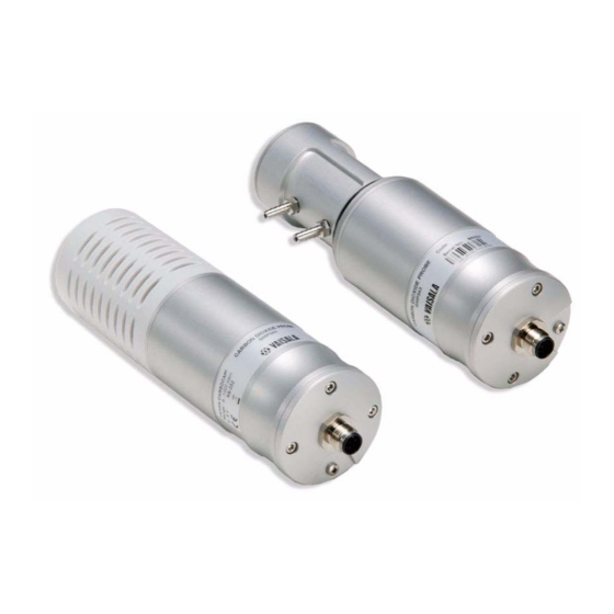
User's Guide ______________________________________________________________________ GMP343 Transmitter Components Figure 1 Two Models of GMP343 The following numbers refer to Figure 1 above. Filter Wiring connector Gas in Gas out Back flange (do not open) NOTE Warranty is void if the back flange of the GMP343 has been opened by the user. -
Page 17: User Configurable Co2 Measurement
Setting the Measurement Range on page 41 Temperature, Pressure, Relative Humidity, and Oxygen Compensations on page Principle of Operation The infra-red sensor of GMP343 is based on the proprietary Vaisala ® CARBOCAP sensing technology. Here the pulsed light from a... -
Page 18: Optics Heating
User's Guide ______________________________________________________________________ When the passband of the FPI coincides with the absorption wavelength of the CO gas, the IR detector sees a decrease in the light transmission. The measurement wavelength of the FPI is then changed to the reference band (that has no absorption lines) and the IR detector sees a full light transmission. -
Page 19: Flow-Through Sampling
If the temperature inside the measurement chamber is essentially higher than the surroundings the cooling coil and the water trap can be simply located outside the chamber. For re-heating, the heat VAISALA _______________________________________________________________________ 17... -
Page 20: Optional Accessories
User's Guide ______________________________________________________________________ generated by a pumping system may sometimes be adequate, meaning that no additional heater is needed. A simplified schema of a sample system removing particles and moisture is illustrated below. All sampling system components are commercially available. Figure 3 Components of the Sampling System Optional Accessories... -
Page 21: Soil Adapter Kits For In-Soil Applications
GMP343. MI70 Indicator Connection Vaisala MI70 indicator is an optional accessory to be used as a display, communication, and data-logging device for GMP343. When taking measurements GMP343 is powered via MI70. -
Page 22: Structure Of The Mi70 Indicator
User's Guide ______________________________________________________________________ Structure of the MI70 Indicator Figure 5 Structure of the MI70 Indicator The following numbers refer to Figure 4 above: Recharging connector Power On/Off key Connection cable (DRW216050SP) for GMP343 connection 20 __________________________________________________________________ M210514EN-C... -
Page 23: Using Mi70 As A Display
Select the language by using the up/down arrow keys. Confirm by pressing the SELECT key. To change the date, select Date and press the SET key. Set the date by using the up/down/left/right arrow keys. To confirm the date, press the OK key. VAISALA _______________________________________________________________________ 21... -
Page 24: Navigation In Menu
User's Guide ______________________________________________________________________ To change the time, select Time and press the SET key. Set the time by using the up/down/left/right arrow keys. To confirm the time, press the OK key. To check and change the environment settings, select YES. Enter ambient pressure, humidity, and oxygen values. -
Page 25: Using Mi70 In Recording
This may cause loss of recorded data. Transferring Recorded Data to PC The recorded data can be transferred to a PC by using MI70 Link program. MI70 Link program can be ordered from Vaisala, see Table 12, List of Spare Parts and Accessories, on page 82. - Page 26 User's Guide ______________________________________________________________________ 24 __________________________________________________________________ M210514EN-C...
-
Page 27: Chapter 3 Installation
A horizontal mounting position is recommended in order to minimize the problems caused by possible condensation. 0704-020 Figure 7 Mounting GMP343 Fasten the GMP343 to the mounting bracket by using the screw provided. Mount the mounting bracket with 4 screws (on corners of the plate). VAISALA _______________________________________________________________________ 25... -
Page 28: Wiring
User's Guide ______________________________________________________________________ Wiring As it is shipped from the factory, the measurement range and output of the GMP343 are scaled according to the order form completed by the customer. The unit is calibrated at the factory. The device is ready for use when the wiring is done and power is switched on. -
Page 29: Wiring Of The Junction Box
RS232 mode by re-configuration via PC . For more information on serial commands and RS232/485 modes, see Chapter 4, Operation, on page Wiring of the Junction Box The optional 8-pole junction box enables practical in-line connection. The box is provided with 8 numbered terminals. VAISALA _______________________________________________________________________ 27... - Page 30 User's Guide ______________________________________________________________________ 28 __________________________________________________________________ M210514EN-C...
-
Page 31: Chapter 4 Operation
Before taking the USB cable into use, you must install the provided USB driver on your PC. When installing the driver, you must acknowledge any security prompts that may appear. The driver is compatible with Windows 2000, Windows XP, Windows Server 2003, and Windows Vista. VAISALA _______________________________________________________________________ 29... -
Page 32: Opening A Terminal Connection
COM port. There is no reason to uninstall the driver for normal use. However, if you wish to remove the driver files and all Vaisala USB cable devices, you can do so by uninstalling the entry for Vaisala USB Instrument Driver from the Add or Remove Programs (Programs and Features in Windows Vista) in the Windows Control Panel. -
Page 33: Table 3 Communication Parameters
Power-up the GMP343. The device should prompt as follows: GMP343 - Version STD 2.0 Copyright: Vaisala Oyj 2003 - 2006 If your device is configured to RS-485 communication mode, switch the device into the service mode by sending a string containing at least 6 capital 'Z' while powering up. -
Page 34: Operation Modes Of The Gmp343
User's Guide ______________________________________________________________________ NOTE Responses from the GMP343 are terminated by the following string: [cr][lf]> That is a carriage return character, a line feed, and a right angle bracket. Operation modes of the GMP343 The GMP343 can operate in three different modes: RUN mode STOP mode POLL mode... -
Page 35: Getting The Measurement Message
Getting the Measurement Message Measurement Units GMP343 outputs the following units: Carbon dioxide (ppm) Temperature (ºC) For other measurement units (%, non-metric units), use the Vaisala MI70 indicator. NOTE Measurement units (ppm and %) express the CO concentration by gas volume.1 % CO... -
Page 36: Setting The Continuous Outputting Interval
User's Guide ______________________________________________________________________ Setting the Continuous Outputting Interval INTV xxxx yyy <cr> SAVE <cr> xxxx=output interval (1...1000) default=1 s yyy=unit (s, min or h) Example: Output interval is changed to 5 seconds >intv 5 s INTERVAL UNIT > Outputting the Reading Once In STOP mode: SEND <cr>... -
Page 37: Setting The Serial Interface Measurement Mode
Communication hardware can be chosen between RS-232 or RS-485. Command parameters are correspondingly 232 and 485. RSMODE <cr> SAVE <cr> The setting is not valid until the device is reset. >rs mode RSMODE : 232? 485 >save EEPROM saved successfully. > VAISALA _______________________________________________________________________ 35... -
Page 38: Serial Communication Settings
User's Guide ______________________________________________________________________ Serial Communication Settings Save the changed settings by entering the SAVE command. The settings are not valid until the device is reset. SERI <cr> SAVE <cr> Baud rate: (300, 600, 1200, 2400, 4800, 9600, 19200, 38400, 57600, 115200) Note: When baud rate is >... -
Page 39: Table 4 Quantities
"" string constant unit field and length Example 1: >form CO2 " " "ppm" #r#n >save EEPROM saved successfully. >send 336.3 ppm Example 2: >form "Filtered data" CO2 "ppm" #r#n >save EEPROM saved successfully > VAISALA _______________________________________________________________________ 37... -
Page 40: Setting Time
User's Guide ______________________________________________________________________ >send Filtered data 336.9ppm > Example 3 (both filtered and raw data chosen): >form CO2 "ppm" " " CO2RAWUC "ppm" #r#n >send 296.5ppm 270.1ppm Setting Time TIME x <cr> SAVE <cr> x=hh:mm:ss Time passed since the last power on was displayed. Time always resets to 00:00:00 when power is switched off. -
Page 41: Networking Operation
The OPEN command sets the bus temporarily in STOP mode so that the SMODE command can be entered. CLOSE <cr> In STOP mode: Command OPEN has no effect, CLOSE sets the transmitter temporarily in POLL mode. In POLL mode: Command OPEN sets the transmitter temporarily in STOP mode. VAISALA _______________________________________________________________________ 39... -
Page 42: Setting Echoing Mode
User's Guide ______________________________________________________________________ Example: >close line closed GMP343: 1 line opened for operator commands >send 351.1 ppm >smode stop SMODE : STOP > Setting Echoing Mode ECHO x <cr> SAVE <cr> x=ON/OFF (default ON) In RS232 mode the device echoes everything back to the user. In RS485 mode echoing is automatically disabled. -
Page 43: Commands During Network Operation
The compensation settings are specific to the selected measurement range, so selecting a suitable measurement range optimizes the compensation performance. Each range also has its own linearization function; see section Linearization on page VAISALA _______________________________________________________________________ 41... -
Page 44: Measurement Data Filtering
User's Guide ______________________________________________________________________ There are 6 measurement ranges available. The range always begins with zero and only upper end value is changed. RANGE x SAVE x = 1...6 Example: >range 4 1. SPAN (ppm) : 1000.00 2. SPAN (ppm) : 2000.00 3. -
Page 45: Median Filter
Table 6 on page 43 presents the measurement noise as a function of averaging time at 370 ppm CO Table 6 Averaging Times Averaging Time Noise 3 ppm 10 s 2 ppm 30 s 1 ppm VAISALA _______________________________________________________________________ 43... -
Page 46: Smoothing Filter
User's Guide ______________________________________________________________________ Smoothing Filter The smoothing filter calculates the running average by weighting the most recent measurement by the user-set proportion of the preceding measurement. By using the smoothing filter, averaging up to even 15 minute periods can be accomplished. The smoothing filter is feasible for the background measurement where fast changes in the CO concentration are not common. -
Page 47: Setting The Median Filter
EEPROM saved successfully (829 ms). > Setting the Smoothing Filter Use the smoothing filter to reduce the noise of the measurement for long averaging periods. Notice the effect on the response time. SMOOTH x <cr> SAVE <cr> x=0...255 (default =0) VAISALA _______________________________________________________________________ 45... -
Page 48: Flushing The Filters (Resynchronization)
User's Guide ______________________________________________________________________ >smooth 10 SMOOTH : 10 >save EEPROM saved successfully (829 ms). > Flushing the Filters (Resynchronization) With this command you can flush the filters to get rid of the effect of the past measurements. This feature is useful if long filtering lengths are used. -
Page 49: Temperature, Pressure, Relative Humidity, And Oxygen Compensations
Without compensation, the effect of oxygen on the CO reading is approximately - 0.09 % of reading / % O . In most circumstances, the oxygen concentration does not vary from the default, so normally there is no need to change the oxygen concentration settings. VAISALA _______________________________________________________________________ 47... -
Page 50: Temperature Compensation On/Off
The internal compensation of GMP343 is the most accurate way to compensate for changing environmental parameters. However, if more information is needed on different compensations, please contact your Vaisala representative. Temperature Compensation ON/ The internal temperature sensor is located in the measurement chamber. -
Page 51: Setting The Oxygen Concentration
O-command if it was saved by SAVE-command. Purpose of the XO-command is continuous update of compensation value sent by another measurement device. Oxygen Compensation Mode To enable or disable the oxygen compensation, use the commands: OC x <cr> SAVE <cr> x=ON/OFF (default =ON) VAISALA _______________________________________________________________________ 49... -
Page 52: Setting The Ambient Pressure (Hpa)
User's Guide ______________________________________________________________________ NOTE Check that the ambient pressure value is correct. The correct pressure value is needed for oxygen compensation even if the pressure compensation is disabled. >oc on OC: ON > >save EEPROM saved successfully. > Setting the Ambient Pressure (hPa) The pressure value is needed in pressure, humidity, and oxygen compensations. -
Page 53: Pressure Compensation On/Off
... 100 % RH (default =50 %) >rh HUMIDITY (%RH): 0.00 ? 24 >save EEPROM saved successfully. > Setting Humidity When the Device Is in POLL-mode To set relative humidity value in POLL-mode, use the following addressable command: XRH addr x <cr> VAISALA _______________________________________________________________________ 51... -
Page 54: Relative Humidity Compensation On/Off
User's Guide ______________________________________________________________________ The device does not reply to the command. If given humidity value is not within limits, the command is rejected. The given value is written to volatile memory, where it will be overwritten either by next XRH- command or RH-command. -
Page 55: Analog Output Hardware
(AHIGH, ALOW). Setting the Limit of the Current Output Range You can expand the current output range for example 4...20 mA to 0...20 mA. The range available is 0...4 mA. ILOW <cr> SAVE <cr> VAISALA _______________________________________________________________________ 53... -
Page 56: Setting The High Limit Of The Voltage Output Range
User's Guide ______________________________________________________________________ Key in the low current value (mA) and press ENTER. >ilow ILOW (mA) : 4.000 >save EEPROM saved successfully. > Setting the High Limit of the Voltage Output Range You can set the hight voltage value: 0...5 V. UHIGH <cr>... -
Page 57: Setting The Low Limit Of The Concentration Range
The voltage output will not go higher than the voltage set with UHIGH. ACUT x <cr> SAVE <cr> x=ON/OFF >acut ACUT : OFF ? ON >acut ACUT : ON ? OFF > >save EEPROM saved successfully. > VAISALA _______________________________________________________________________ 55... -
Page 58: Testing The Analog Output
User's Guide ______________________________________________________________________ Testing the Analog Output When you want to test the operation of the analog output use this command to force the output to the set value. The value in the analog output can then be measured with a current/voltage meter. The set value remains valid until you give the ATEST command without a value or RESET the transmitter. -
Page 59: Device Information And Other General Commands
?? <cr> >?? GMP343 / 2P0.33 SNUM : Y3040008 CALIBRATION : 2007-04-20 CAL. INFO : Vaisala Oyj SPAN (ppm) : 4000 PRESSURE (hPa) : 1013.000 HUMIDITY (%RH) : 50.00 OXYGEN (%) : 20.95 : ON : OFF : ON... -
Page 60: Linear And Multipoint Corrections
User's Guide ______________________________________________________________________ - Error flag - Gas temperature - User-set pressure value - User-set relative humidity value - User-set oxygen value Linear and Multipoint Corrections Shows the last linear and multipoint correction values. CORR <cr> >corr : OFF Linear correction Reading Reference 0.00... -
Page 61: Command List
ILOW (mA) : 4.00 UHIGH (V) : 2.50 RANGE MEDIAN AVERAGE (s) : 30 SMOOTH LINEAR : ON : OFF : OFF HEAT : OFF OXYGEN (%) : 20.95 PRESSURE (hPa) : 1013.000 HUMIDITY (%RH) : 50.00 VAISALA _______________________________________________________________________ 59... -
Page 62: Software Version Information
User's Guide ______________________________________________________________________ : OFF : ON : OFF : ON Software Version Information VERS <cr> >vers GMP343 / 2P0.33 > Memory Handling Reverting the Factory Parameters Use this command to revert the original factory settings. >factory Parameters loaded from Flash. >... -
Page 63: Setting The Optics Heating On/Off
OFF (default =ON) Example: >heat HEAT : ON ? off > Resetting the Transmitter RESET <cr> This command resets the device. If the device is in RUN mode, outputting the results starts immediately after resetting. VAISALA _______________________________________________________________________ 61... - Page 64 User's Guide ______________________________________________________________________ 62 __________________________________________________________________ M210514EN-C...
-
Page 65: Calibration And Adjustment
After adjustment, the original calibration certificate shipped with the product is not valid anymore. The GMP343 can be sent to Vaisala for calibration, or be calibrated by the user. Calibration Interval GMP343 is calibrated as shipped from the factory. The recommended calibration interval is one year. -
Page 66: Factory Calibration And Adjustment
User's Guide ______________________________________________________________________ Factory Calibration and Adjustment You can send the device to Vaisala Service Center for calibration and adjustment, for more information, see, Vaisala Service Centers, on page Calibration and Adjustment by the User Calibration and adjustment are carried out by using the serial communications and the calibration gas(es). -
Page 67: Measurements In Reference Gases
CO reading (ppm). Enter command S to stop outputting. For the best calibration result, it is recommended to calculate an average of 20 measurements instead of a single reading. VAISALA _______________________________________________________________________ 65... -
Page 68: Adjustment In 1
User's Guide ______________________________________________________________________ Shut off the reference gas flow and remove the tubings from the gas bottle. When calibrating at several points, connect the other gases to GMP343 similar to the first gas and carry out the measurements as instructed above (steps 6 and 7). After measurements turn off the calibration mode by giving the command CALIB OFF (this reverts to the original transmitter settings). -
Page 69: Adjustment In 3
Use CALIB OFF to stop the mode. The GMP is now measuring the first reference gas (0 ppm). Use command R and let the reading stabilize for several minutes. Calculate the average reading (reading 1). > ...28.2 28.2 28.1 28.1 28.2 VAISALA _______________________________________________________________________ 67... - Page 70 User's Guide ______________________________________________________________________ The GMP343 is now measuring the second reference gas (1007 ppm). Use command R and let the reading stabilize for several minutes. Calculate the average reading (reading 2). > >r 1067.1 1066.8 1067.2 1066.7 1066.6 Turn off the calibration mode with command CALIB OFF. >calib off Calibration mode stopped.
- Page 71 Chapter 5 __________________________________________________ Calibration and Adjustment Check the reading with the first reference gas, 0 ppm. > -0.1 -0.1 -0.0 -0.2 Save the settings. save> EEPROM saved successfully. > NOTE The factory settings can be reverted with the command FACTORY. VAISALA _______________________________________________________________________ 69...
- Page 72 User's Guide ______________________________________________________________________ 70 __________________________________________________________________ M210514EN-C...
-
Page 73: Chapter 6 Maintenance
Chapter 6 ______________________________________________________________ Maintenance CHAPTER 6 MAINTENANCE This chapter instructs in the basic maintenance of the GMP343. Cleaning the Optics (Diffusion Model Only) 0704-021 Figure 10 Optics The following numbers refer to Figure 10 on page Mirror Window VAISALA _______________________________________________________________________ 71... - Page 74 User's Guide ______________________________________________________________________ NOTE Handle the diffusion filter carefully to prevent contaminants or mechanical stress from damaging the filtering surface. Rotate and remove the filter cover. Take a firm hold on the frame of the diffusion filter, and pull it out. Note that the threads for the filter cover are sharp.
-
Page 75: Changing The Filter (Diffusion Model Only)
Chapter 6 ______________________________________________________________ Maintenance Changing the Filter (Diffusion Model Only) The diffusion filter should be changed when it looks dirty. A new standard diffusion filter and filter cover can be ordered from Vaisala with the order code GMP343FILTER. NOTE Handle the diffusion filter carefully to prevent contaminants or mechanical stress from damaging the filtering surface. -
Page 76: Error States
Analog output: Error is -45...+85 °C (- level is shown if 49...185 °F). In case of temperature constant error, return compensation is the device to Vaisala enabled. Otherwise, Service. output is normal. Measurement signal Measurement chamber Clean the optics and the... -
Page 77: Technical Support
Include the information specified in step 2 in the box with the faulty product. Also include a detailed return address. Ship the box to the address specified by your Vaisala contact. VAISALA _______________________________________________________________________ 75... -
Page 78: Vaisala Service Centers
Phone: +81 3 3266 9617, Fax: +81 3 3266 9655 E-mail: aftersales.asia@vaisala.com BEIJING SERVICE CENTER Vaisala China Ltd., Floor 2 EAS Building, No. 21 Xiao Yun Road, Dongsanhuan Beilu, Chaoyang District, Beijing, P.R. CHINA 100027. Phone: +86 10 8526 1199, Fax: +86 10 8526 1155 E-mail: china.service@vaisala.com... -
Page 79: Technical Data
0 ... 2000 ppm - 0 ... 2 %* ± (5 ppm CO + 2 % of reading) factory calibration with 0.5 % accurate gases with different range options * Accuracy below 200 ppm CO not specified for the 2 % range option VAISALA _______________________________________________________________________ 77... -
Page 80: And Oxygen
User's Guide ______________________________________________________________________ Noise (repeatability) at with no output averaging ± 3 ppm CO 370 ppm CO with 30 s output averaging ± 1 ppm CO Short-term stability (up to ± 1 ppm CO 6 hours) at 370 ppm CO Long-term stability In easy operating conditions <... -
Page 81: Pressure
For more information on operating humidity range, see the graph in section, Operating Conditions, on page Oxygen Effect on accuracy with oxygen compensation at 20.9 %O ± 0.2 % of reading Effect on accuracy without oxygen compensation (typ.): - 0.09 % of reading / %O VAISALA _______________________________________________________________________ 79... -
Page 82: Response Time (90 %)
User's Guide ______________________________________________________________________ Response time (90 %) Table 10 Diffusion Model Filter attached Averaging (s) Response (s) < 2 Table 11 Flow-through Model Gas flow (l/min) Averaging (s) Response (s) Flow dependence of flow- 0.3 % of reading / 1 / min through model Warm-up time full accuracy ±... -
Page 83: Operating Conditions
0 ... 100 %O Gas flow rate for flow-through model < 10 litres / min Internal volume of the measurement 59 ml ± 1 ml chamber of flow-through model Electromagnetic compatibility Complies with EMC standard EN61326-1:1997+Am1:1998, Generic Environment VAISALA _______________________________________________________________________ 81... -
Page 84: Materials
User's Guide ______________________________________________________________________ Materials Housing anodized aluminium Filter cover polycarbonate Filters PTFE IP classification Housing (cable attached) IP67 Diffusion filter (weather protection) IP65 Diffusion filter (sintered PTFE) IP66 Cable connector type 8-pin M12 Weight (probe only) 360 g Spare Parts and Accessories Table 12 List of Spare Parts and Accessories Description... -
Page 85: Appendix Adimensions
Appendix A ______________________________________________________________ Dimensions APPENDIX A DIMENSIONS This appendix contains the dimension drawings for the GMP343. VAISALA _______________________________________________________________________ 83... -
Page 86: Gmp343 (Flow-Through)
User's Guide ______________________________________________________________________ GMP343 (Flow-through) 1.77 2.17 84 __________________________________________________________________ M210514EN-C... -
Page 87: Gmp343 (Diffusion)
Appendix A ______________________________________________________________ Dimensions GMP343 (Diffusion) 2.07 52.5 2.17 VAISALA _______________________________________________________________________ 85... -
Page 88: Calibration Cap
User's Guide ______________________________________________________________________ Calibration Cap 86 __________________________________________________________________ M210514EN-C... -
Page 89: Mounting Flange
Appendix A ______________________________________________________________ Dimensions Mounting Flange VAISALA _______________________________________________________________________ 87... -
Page 90: Junction Box
User's Guide ______________________________________________________________________ Junction Box 88 __________________________________________________________________ M210514EN-C... -
Page 91: Mounting Bracket
Appendix A ______________________________________________________________ Dimensions Mounting Bracket VAISALA _______________________________________________________________________ 89... - Page 92 User's Guide ______________________________________________________________________ 90 __________________________________________________________________ M210514EN-C...
-
Page 93: Appendix Blist Of Commands
Set the device address CLOSE Close the line to POLL mode OPEN Open temporarily connection to the POLL-mode device FORM Set the output format of SEND and R commands RSMODE Set the output hardware to use either RS-232 or RS-485 VAISALA _______________________________________________________________________ 91... -
Page 94: Filtering Commands
User's Guide ______________________________________________________________________ Filtering Commands AVERAGE Set the averaging filter SMOOTH Set the smoothing filter MEDIAN Set the median filter RESYNC Flush (clear) all the filters P, T and RH Compensation Commands Set local pressure (hPa) for compensation Pressure compensation mode Set local humidity (% RH) for compensation Humidity compensation mode Temperature compensation mode... -
Page 95: Calibration Commands
UHIGH Analog output high voltage value AERR Change the analog error output value ATEST Test the analog outputs Advanced Measurement Commands LINEAR Set linearization ON/OFF HEAT Set optics heating ON/OFF RANGE Set measurement range to optimize performance VAISALA _______________________________________________________________________ 93... - Page 96 User's Guide ______________________________________________________________________ 94 __________________________________________________________________ M210514EN-C...
Need help?
Do you have a question about the CARBOCAP GMP343 and is the answer not in the manual?
Questions and answers