
Related Manuals for Vaisala DMP Series


Summary of Contents for Vaisala DMP Series
- Page 1 M212357EN-D User Guide Vaisala Indigo-compatible dew point and temperature probes DMP Series...
- Page 2 English versions are This product contains software developed applicable, not the translations. by Vaisala or third parties. Use of the The contents of this document are subject software is governed by license terms and to change without prior notice.
-
Page 3: Table Of Contents
FCC Part 15 compliance statement............16 2.7.2 Canada ICES‑3 / NMB‑3 compliance statement........17 Functional description.................18 DRYCAP® technology..................18 3.1.1 DRYCAP® sensor models in DMP Series probes........18 Autocalibration....................18 Sensor purge....................19 Condensation prevention functions.............. 19 Environmental compensation...............20 Filtering factor....................21 Installation....................... 22 DMP5 probe.....................23... - Page 4 DMP Series User Guide M212357EN-D Using probe with Indigo transmitters..........42 Connecting probe to Indigo200 series transmitters......... 42 Connecting probe to Indigo300 transmitter..........43 Connecting probes to Indigo500 series transmitters....... 44 Using probe with Indigo80 handheld indicator......46 Indigo80 handheld indicator................ 46 7.1.1...
- Page 5 Table of contents Modbus communication examples...............85 Maintenance and calibration services............89 Warranty......................89 Technical support.................... 89 Recycling......................89...
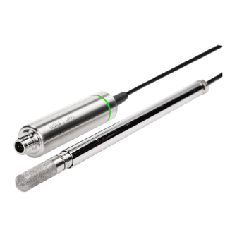
- Page 6 DMP Series User Guide M212357EN-D List of figures Figure Probe parts......................13 Figure 2 Example installation..................22 Figure 3 DMP5 dimensions....................23 Figure 4 DMP6 probe dimensions................25 Figure 5 Cooling Set DMP246CS dimensions............25 Figure 6 Operating range of DMP6 probe head............26 Figure 7 DMP246CS Cooling Set mounting flange..........27...
- Page 7 Table Document versions (English)................9 Table 2 Related manuals....................11 Table 3 Availability of output parameters..............14 Table 4 DRYCAPâ sensor models in DMP Series probes........18 Table 5 Troubleshooting table..................55 Table 6 DMP5 measurement performance............... 59 Table 7 DMP5 operating environment...............60 Table 8 DMP5 inputs and outputs................60...
- Page 8 DMP Series User Guide M212357EN-D...
-
Page 9: About This Document
Chapter 1 – About this document 1. About this document 1.1 Version information This document provides instructions for installing, using, and maintaining Vaisala DRYCAPâ Dew Point and Temperature Probes DMP5, DMP6, DMP7, and DMP8. Table 1 Document versions (English) Document code Date Description... -
Page 10: Related Manuals
DMP6 probe (page 25) • DMP7 probe (page 30) • Vaisala Insight software (page 38) • Error messages (page 55) • Mechanical specifications tables and dimension drawings in chapter Technical data 1.2 Related manuals For the latest versions of these documents, see docs.vaisala.com. -
Page 11: Documentation Conventions
Table 2 Related manuals Document code Name M212356EN Vaisala DMP Series Quick Guide M212842EN Vaisala Indigo201 Analog Output Transmitter User Guide M212843EN Vaisala Indigo202 Digital Transmitter User Guide M212287EN Vaisala Indigo500 Series Transmitters User Guide M212722EN Vaisala Indigo80 Handheld Indicator User Guide 1.3 Documentation conventions... -
Page 12: Trademarks
DMP Series User Guide M212357EN-D 1.4 Trademarks Vaisalaâ and DRYCAPâ are registered trademarks of Vaisala Oyj. All other product or company names that may be mentioned in this publication are trade names, trademarks, or registered trademarks of their respective owners. -
Page 13: Product Overview
Chapter 2 – Product overview 2. Product overview DMP series probes are dew point and temperature measurement probes with a digital output (Modbusâ protocol). The probes are designed for demanding dew point measurement applications. The probes have a two-part structure, with measurement electronics contained in the probe body and sensor(s) in the probe head. -
Page 14: Output Parameters
DMP Series User Guide M212357EN-D • Can be connected to Vaisala Insight PC software for configuration, calibration, diagnostics, and temporary online monitoring 2.3 Output parameters Values of all available output parameters are locked (showing the latest valid value) when sensor purge, autocalibration, or condensation prevention functions are active. -
Page 15: Additional Features With Indigo Transmitters
• Numerical and graphical display for real-time data viewing • 3 pre-configurable analog outputs • Service port on the front for connecting to Vaisala Insight PC software or Indigo80 handheld indicator for easy configuration access Examples of additional features available with Indigo200 series transmitters: •... -
Page 16: Esd Protection
2.6 ESD protection Electrostatic discharge (ESD) can cause immediate or latent damage to electronic circuits. Vaisala products are adequately protected against ESD for their intended use. However, it is possible to damage the product by delivering an electrostatic discharge when touching, removing or inserting any objects inside the equipment housing. -
Page 17: Canada Ices-3 / Nmb-3 Compliance Statement
Chapter 2 – Product overview This device complies with part 15 of the FCC Rules. Operation is subject to the following two conditions: (1) This device may not cause harmful interference, and (2) this device must accept any interference received, including interference that may cause undesired operation. -
Page 18: Functional Description
During autocalibration the values of all available output parameters are locked (showing the latest valid value). DMP series probes perform autocalibration at 1-hour intervals, and whenever sensor purge is performed. When measuring very dry conditions, the probe performs autocalibration at shorter intervals. -
Page 19: Sensor Purge
(known as interval purge). If necessary, the purge settings can be configured with the Insight software, the Indigo80 handheld indicator, or using the Modbus protocol. However, Vaisala recommends leaving the sensor purge settings at their default values. -
Page 20: Environmental Compensation
DMP Series User Guide M212357EN-D 3.5 Environmental compensation Environmental compensations improve the measurement accuracy of the probe. You can configure the settings with the Insight software or the Indigo80 handheld indicator, or using the Modbus protocol. Pressure compensation The pressure of the measured environment affects the accuracy of humidity calculations, especially calculations that are dependent on pressure (for example, mixing ratio). -
Page 21: Filtering Factor
Chapter 3 – Functional description More information ‣ Configuring environment settings with Indigo80 handheld indicator (page 51) 3.6 Filtering factor The filtering factor determines how quickly the results of measurement cycles are reflected in values of output parameters. You can use the filtering factor to slow down the response time of the measurement, filtering out rapid changes and measurement noise. -
Page 22: Installation
DMP Series User Guide M212357EN-D 4. Installation When you choose the installation location for the probe, consider the following: • Verify the operating environment specification of the probe model. The probe head typically has a much wider operating temperature range than the probe body. -
Page 23: Dmp5 Probe
41 [1.61] Figure 3 DMP5 dimensions Vaisala DRYCAPâ Dew Point and Temperature Probe DMP5 is designed for humidity measurement in applications with high temperatures. The long and robust steel probe and an optional installation flange allow easy installation with adjustable depth through insulation, for example, in ovens. -
Page 24: Installing With Mounting Flange 210696
DMP Series User Guide M212357EN-D 4.1.1 Installing with Mounting Flange 210696 Mounting Flange 210696 is designed for attaching Ø13.5 mm probe heads through the wall of a process chamber or duct. The flange kit includes a flange, a sealing ring, and screws. -
Page 25: Dmp6 Probe
Chapter 4 – Installation 4.2 DMP6 probe Probe body 136 [5.35] [in] M12/5 Fixed probe cable Probe head 357 [14.1] 334.5 [13.17] Figure 4 DMP6 probe dimensions 304 [11.97] 112.5 [4.43] 164 [6.46] 8 [0.31] 15 [0.59] 27.5 [1.08] 40.6 [1.6] Ø 118 [4.65] Ø... -
Page 26: Figure 6 Operating Range Of Dmp6 Probe Head
DMP Series User Guide M212357EN-D Vaisala DRYCAPâ Dew Point Probe DMP6 is designed for humidity measurement in industrial applications with very high temperatures. High temperature tolerance is achieved using a passive cooling set that conducts heat away from the probe and reduces temperature to optimal range for the sensor. -
Page 27: Installing Probe Head With Cooling Set Dmp246Cs
Chapter 4 – Installation You can read diagnostic measurement data from the probe using Insight software (Diagnostics page) or Modbus protocol (diagnostic data registers) and use it to verify your installation: • Sensor temperature must never exceed +180 °C (+356 °F) even in exceptional process conditions. -
Page 28: Figure 8 Dmp246Cs Cooling Set Without Mounting Flange
DMP Series User Guide M212357EN-D 22 [0.87] 172 [6.77] 104.5 [4.11] [in] Figure 8 DMP246CS Cooling Set without mounting flange Cooling bush Flange Cooling bar Locking screws (4 pcs, M4×6 DIN 916) Mounting screws of the cooling fins (M6×60 DIN 912) 1. -
Page 29: Cooling Set Installation Example
Chapter 4 – Installation 7. Push the probe head into the cooling bar until it meets the other end and cannot be pushed farther. Approximately 7.5 cm (2.95 in) of the probe head will remain outside the cooling bar. CAUTION! Do not push or pull from the probe cable. -
Page 30: Dmp7 Probe
41 [1.61] Figure 10 DMP7 dimensions Vaisala DRYCAPâ Dew Point and Temperature Probe DMP7 is designed for low-humidity applications. Thanks to its short probe length, it fits in installations with limited space, such as semiconductor manufacturing equipment. Other applications include industrial drying, compressed air systems, dry rooms, and blanket gases in metal heat treatment. -
Page 31: Figure 11 Dmp7 Installation To Pipeline Using A Swagelok Installation Kit
Chapter 4 – Installation CAUTION! Note that overtightening the connector may damage the probe head. 84 [3.31] 42 [1.65] [in] Figure 11 DMP7 installation to pipeline using a Swagelok installation kit Max. process pressure 10 bar (145 psi), max temperature +80 °C (+176 °F) Probe head Duct connector ISO1/2", ISO3/8"... -
Page 32: Dmp8 Probe
ISO 1/2” or NPT 1/2” Figure 12 DMP8 dimensions Vaisala DRYCAPâ Dew Point and Temperature Probe DMP8 is designed for industrial low- humidity applications such as industrial drying, compressed air systems, and semiconductor industry. It can be installed in a 1/2" NPT or ISO thread with adjustable insertion depth. -
Page 33: Figure 13 Dmp8 Probe Head
Chapter 4 – Installation Figure 13 DMP8 probe head Clasp nut, 24 mm hex nut Fitting body, 27 mm hex head Leak screw (on ISO 1/2" fitting body HM47432 only) Fitting body with a leak screw can be useful when the probe head cannot be installed directly in the pressurized process or process pipe. -
Page 34: Tightening The Clasp Nut
DMP Series User Guide M212357EN-D Follow the instructions of the sealant manufacturer. PTFE tape does not lock the parts together. Use two fork wrenches (24 mm and 27 mm) when tightening and opening the clasp nut of the probe. 4.4.1 Tightening the clasp nut 1. -
Page 35: Dmt242Sc2 Sampling Cell With Swagelok Connectors
To fit 6 mm tubing to the connectors, an adapter such as Swagelokâ Reducer SS-6M0-R-4 (not supplied by Vaisala) can be used. DMT242SC2 is the suitable choice in, for example, plastics drying systems, where the measurement is made by tapping off the dryer system and bringing a small air stream to the sensor. -
Page 36: Wiring
DMP Series User Guide M212357EN-D 4.5 Wiring Figure 16 M12 5-pin A-coded male connector pinout Pin # Function Notes Wire colors in Vaisala cables Power supply Operating voltage: 15 ... 30 V DC Brown Current consumption: 10 mA typical, 500 mA max. -
Page 37: Configuring Environmental Compensations
Chapter 4 – Installation 4.6 Configuring environmental compensations After installation, configure the pressure compensation setting, if relevant to your probe and its measurement environment. For example, when you have installed the probe in a process with a pressure differing from normal atmospheric pressure, update the correct pressure into the pressure compensation setpoint parameter or register of the probe. -
Page 38: Configuration With Insight Software
Series probes. If adjustment is necessary, contact Vaisala. See Maintenance and calibration services (page 89). Microsoft Windowsâ operating system and Indigo USB adapter (item code USB2) or Vaisala USB cable (item code 242659) required. Download Vaisala Insight software at www.vaisala.com/insight. 5.2 Connecting to Insight software •... -
Page 39: Configuration Options
• Basic mode is suitable for most use cases. • Advanced mode provides access to additional configuration options. Use Advanced mode only when instructed to do so by product documentation or Vaisala technical support. 3. Connect the USB adapter to a free USB port on the PC or USB hub. -
Page 40: Diagnostics In Insight
Both files contain data from since the probe was manufactured, or since the files were last cleared. Clearing the files is not recommended unless instructed by Vaisala support. The buttons to clear the files are located at the bottom of the Diagnostics page. -
Page 41: Figure 20 Dmp5 Diagnostics In Insight (Advanced Mode)
Chapter 5 – Configuration with Insight software Figure 20 DMP5 diagnostics in Insight (advanced mode) -
Page 42: Using Probe With Indigo Transmitters
For more information on the features of the different Indigo transmitter models, see www.vaisala.com/indigo. For instructions on installing and configuring Indigo transmitters, see the applicable Indigo transmitter user documentation available at the Vaisala documentation portal docs.vaisala.com. 6.1 Connecting probe to Indigo200 series... -
Page 43: Connecting Probe To Indigo300 Transmitter
Indigo300 transmitters have a probe connector where compatible probes can be attached directly. A cable may also be used to connect the probe. Cables are available to order at store.vaisala.com. CAUTION! The IP classification of probes is valid only when the probes are connected to the probe connection cable, or to the cable connector inside the locking wheel of the transmitter. -
Page 44: Connecting Probes To Indigo500 Series Transmitters
DMP Series User Guide M212357EN-D OPEN >> OPEN >> Figure 22 Connecting probe to Indigo300 transmitter 1. Insert the probe or the cable into the transmitter's connector. 2. Turn the locking wheel of the transmitter to lock the probe or cable in place. Do not turn the probe or the cable itself, as that will damage the connectors. -
Page 45: Figure 23 Connecting Probes To Indigo500 Transmitter
Chapter 6 – Using probe with Indigo transmitters Probes are connected to Indigo500 series transmitters using a cable. Connections are made to the screw terminals inside the housing. The Indigo520 model allows 2 probes to be connected. After connecting a probe, use the touchscreen interface or the web user interface to configure the transmitter. -
Page 46: Using Probe With Indigo80 Handheld Indicator
7. Using probe with Indigo80 handheld indicator 7.1 Indigo80 handheld indicator Figure 24 Indigo80 handheld indicator Vaisala Indigo80 Handheld Indicator is a portable diagnostics tool that accommodates up to two Vaisala Indigo-compatible probes or transmitters for measuring a wide range of parameters. With the indicator, you can: •... -
Page 47: Probe Compatibility
Indigo80 menu for changing the settings of Indigo80 (for example, date, time, and language) and viewing device information. Help menu contains a Getting started tour showing the key features of Indigo80, as well as instructions for sending devices to Vaisala for calibration and maintenance. -
Page 48: Connecting Probes To Indigo80
7.2 Connecting probes to Indigo80 • Probe connection cable Up to two Vaisala Indigo-compatible probes or transmitters can be connected to the ports located on the bottom of Indigo80. You can connect and disconnect devices both when the indicator is powered on and when it is off. -
Page 49: Configuring Probe Features With Indigo80 Handheld Indicator
Chapter 7 – Using probe with Indigo80 handheld indicator 2. Insert the probe connection cable in one of the ports on the bottom of the indicator. • Note the orientation of the cable connector when inserting it • Hold the connector in place while turning its locking ring clockwise – never twist the connector body! 3. -
Page 50: Example Of Configuring Filtering Factor With Indigo80 Handheld Indicator
DMP Series User Guide M212357EN-D Accessing certain configuration options for your probe requires using the free Insight PC software, downloadable at www.vaisala.com/insight. 1. Connect the probe(s) to the indicator. 2. Open the main menu by pressing 3. Select Devices. If you have more than one device connected to the indicator, make a further selection between the devices. -
Page 51: Configuring Environment Settings With Indigo80 Handheld Indicator
Chapter 7 – Using probe with Indigo80 handheld indicator 6. Select Extended filtering on/off > On to enable measurement filtering using the filtering factor defined in the previous step. 7. Exit the menu by pressing or return to the main menu by pressing More information ‣... - Page 52 DMP Series User Guide M212357EN-D 4. Select Environment settings to access the settings for your probe. The available environment settings depend on the probe and probe firmware version. Pressure Value for pressure compensation. The current value is stored in non-volatile memory when the device is turned off, and restored at power-up.
-
Page 53: Maintenance
Chapter 8 – Maintenance 8. Maintenance 8.1 Cleaning the probe CAUTION! Do not attempt to clean the sensors under the filter. Do not spray anything directly on the probe head, since that may deposit impurities on the sensors. You can clean the probe, probe body, and cable by wiping them with a soft, lint-free cloth moistened with water or a suitable cleaning agent, such as isopropyl alcohol. -
Page 54: Calibration And Adjustment
When adjustment is necessary, have Vaisala calibrate and adjust the probe. Factory calibration leads to highest accuracy and lowest uncertainty. After factory calibration the instrument performs as new. -
Page 55: Troubleshooting
See Installation (page 22). Probe is in need of adjustment Have the probe adjusted by Vaisala. See Calibration and adjustment (page 54). Probe status indicator LED is Probe is in error state Connect the probe to Insight... - Page 56 DMP Series User Guide M212357EN-D Error message Description Recommended action Critical errors Firmware checksum mismatch The installed firmware is Contact Vaisala technical [49] corrupted. support. Device settings corrupted [50] Parameter memory is corrupted. Additional configuration settings corrupted [51] Sensor coefficients corrupted...
-
Page 57: Restoring Factory Default Settings With Insight Software
Calibration certificate Certificate stored in the probe Contact Vaisala technical checksum mismatch [58] has an invalid checksum. support Calibration has expired [353] This warning is displayed by... -
Page 58: Restoring Factory Default Settings With Indigo80 Handheld Indicator
DMP Series User Guide M212357EN-D More information ‣ Connecting to Insight software (page 38) 9.4 Restoring factory default settings with Indigo80 handheld indicator • Probe connection cable If needed, you can restore the probe back to its factory default settings using the Indigo80 handheld indicator. -
Page 59: Technical Data
Chapter 10 – Technical data 10. Technical data 10.1 DMP5 specifications Table 6 DMP5 measurement performance Property Description/Value Dew point Sensor DRYCAPâ 180S Measurement range −40 … +100 °C (−40 … +212 °F) T Accuracy ±2 °C (±3.6 °F) T See accuracy graph Response time 63 % [90 %] From dry to wet 5 s [10 s]... -
Page 60: Figure 28 Dmp5 Dew Point Accuracy Vs. Measurement Conditions
For air, nitrogen, hydrogen, argon, helium, and oxygen IP rating for probe body IP66: Dust-tight. Protected from powerful water jets from any direction. Consult Vaisala if other chemicals are present. Consider safety regulations with flammable gases. Table 8 DMP5 inputs and outputs Property Description/Value Operating voltage 15 …... -
Page 61: Dmp6 Specifications
Chapter 10 – Technical data Table 9 DMP5 mechanical specifications Property Description/Value Connector M12 5-pin A-coded male Weight 436 g (15.37 oz) Probe cable length 2 m (6.56 ft) or 10 m (32.8 ft) Materials Probe AISI 316L Probe body AISI 316L Cable jacket Probe body 136 [5.35] [in]... -
Page 62: Table 11 Dmp6 Operating Environment
The operating range specifications apply in stand-still air. High flow rates in the process may reduce the probe performance and cause damage to the equipment. Consult Vaisala if other chemicals are present. Consider safety regulations with flammable gases. -
Page 63: Figure 30 Operating Range Of Dmp6 Probe Head
Chapter 10 – Technical data Temperature of measured gas (°C) Figure 30 Operating range of DMP6 probe head Table 12 DMP6 inputs and outputs Property Description/Value Operating voltage 15 … 30 V DC Current consumption 10 mA typical, 500 mA max. Digital output RS-485, non-isolated Protocols Modbus RTU... -
Page 64: Figure 31 Dmp6 Dimensions With Cooling Set Dmp246Cs
DMP Series User Guide M212357EN-D Probe body 136 [5.35] [in] M12/5 Fixed probe cable Probe head 304 [11.97] 112.5 [4.43] 191.5 [7.54] 40.6 [1.6] Ø 118 [4.65] Ø 89 [3.5] Sintered filter Cooling fins Mounting flange Screen tube of the cooling set... -
Page 65: Figure 32 Dmp6 Probe Dimensions
Chapter 10 – Technical data Probe body 136 [5.35] [in] M12/5 Fixed probe cable Probe head 357 [14.1] 334.5 [13.17] Figure 32 DMP6 probe dimensions 304 [11.97] 112.5 [4.43] 164 [6.46] 8 [0.31] 15 [0.59] 27.5 [1.08] 40.6 [1.6] Ø 118 [4.65] Ø... -
Page 66: Dmp7 Specifications
DMP Series User Guide M212357EN-D 10.3 DMP7 specifications Table 14 DMP7 measurement performance Property Description/Value Dew point Sensor DRYCAPâ 180M Measurement range −70 … +80 °C (−94 … +176 °F) T Measurement range for continuous use −70 … +45 °C (−94 … +113 °F) T Accuracy Up to ±2 °C (±3.6 °F) T... -
Page 67: Figure 34 Dmp7 Dew Point Accuracy Vs. Measurement Conditions
Mechanical durability of probe head Up to +180 °C (+356 °F) Up to 10 bar/145 psia Consult Vaisala if other chemicals are present. Consider safety regulations with flammable gases. Table 16 DMP7 inputs and outputs Property Description/Value Operating voltage 15 …... -
Page 68: Dmp8 Specifications
DMP Series User Guide M212357EN-D Table 17 DMP7 mechanical specifications Property Description/Value Connector M12 5-pin A-coded male Weight 310 g (10.9 oz) with 2 m (6.56 ft) cable Probe cable length 2 m (6.56 ft) or 10 m (32.80 ft) Materials... -
Page 69: Figure 36 Dmp8 Dew Point Accuracy Vs. Measurement Conditions
Chapter 10 – Technical data Property Description/Value Measurement range for continuous use −70 … +45 °C (−94 … +113 °F) T Accuracy up to 20 bar/290 psia ±2 °C/±3.6 °F T See accuracy graph Accuracy, 20 … 40 bar/290 … 580 psia Additional inaccuracy +1 °C T Response time 63 % [90 %] From dry to wet... -
Page 70: Table 19 Dmp8 Operating Environment
Mechanical durability of probe head Up to +180 °C (+356 °F) Up to 70 bar/1015 psia Consult Vaisala if other chemicals are present. Consider safety regulations with flammable gases. Table 20 DMP8 inputs and outputs Property Description/Value Operating voltage 15 …... -
Page 71: Accessories And Spare Parts
ISO 1/2” or NPT 1/2” Figure 37 DMP8 dimensions 10.5 Accessories and spare parts Information on spare parts, accessories, and calibration products is available online at www.vaisala.com and store.vaisala.com. Connection cables Table 22 Connection cables Description Item code Connection cable, M12-5F - M12-5M, 1 m... -
Page 72: Table 23 Dmp5 Accessories
Flat cable, M12-5F - M12-5M, 1 m CBL210493SP Connection cable for Indigo80, M12-5F - M12-5M, 272075SP 1.5 m USB2 Vaisala Indigo USB adapter Vaisala Insight software for Windows available at www.vaisala.com/insight DMP5 Table 23 DMP5 accessories Description Vaisala item code Mounting flange 210696 Table 24 DMP5 spare parts... -
Page 73: Table 27 Dmp7 Accessories
Chapter 10 – Technical data DMP7 Table 27 DMP7 accessories Description Vaisala item code Swagelok ISO 3/8" SWG12ISO38 Swagelok ISO 1/2" SWG12ISO12 Swagelok NPT 1/2" SWG12NPT12 Magnetic probe holder for Ø 12 mm probe heads ASM213382SP Not suitable for use at extreme temperatures. - Page 74 DMP Series User Guide M212357EN-D Description Vaisala item code Stainless steel filter for vacuum HM47453SP Manual pressing handle HM36854SP...
-
Page 75: Appendix A: Modbus Reference
Appendix A – Modbus reference Appendix A. Modbus reference A.1 Default communication settings Table 31 Default Modbus serial communication settings Property Description/Value Serial bit rate 19200 Parity None Number of data bits Number of stop bits Flow control None Modbus device address You can use up to ten probes on the same RS-485 line. You must configure each probe on the line to have a different Modbus address. -
Page 76: 32-Bit Floating Point Or 32-Bit Integer Format
DMP Series User Guide M212357EN-D A.3.1 32-bit floating point or 32-bit integer format Registers using 32-bit float data format are encoded using the binary32 encoding defined in IEEE 754. The format is also known as "single-precision floating point format". The least significant 16 bits of a floating point number are placed at the Modbus register listed in the table, while the most significant 16 bits are placed in the register with number/ address + 1, as specified in Open Modbus TCP Specification, Release 1.0. -
Page 77: Modbus Registers
Appendix A – Modbus reference A.4 Modbus registers Registers are numbered in decimal, starting from 1. Register addresses in actual Modbus messages (Modbus Protocol Data Unit (PDU)) are in hexadecimal and start from zero. Register number 1 corresponds to address 0 in the actual Modbus message. -
Page 78: Table 35 Integer Measurement Data Registers (Read-Only)
DMP Series User Guide M212357EN-D Table 35 Integer measurement data registers (read-only) Register Address Description Data format Scale Offset Unit number factor 0100 Relative humidity 16-bit signed integer 0101 Temperature 16-bit signed °C integer 0103 Dew point 16-bit signed °C temperature... -
Page 79: Diagnostic Data Registers
Appendix A – Modbus reference A.4.2 Diagnostic data registers Table 36 Floating point diagnostic data registers (read-only) Register Address Description Data format Unit number 0024 Sensor saturation ratio 32-bit float 0026 Sensor temperature 32-bit float °C Table 37 Integer diagnostic data registers (read-only) Register Address Register description... - Page 80 DMP Series User Guide M212357EN-D Sensor purge 1283 0502 Interval purge on/off 16-bit 0 = Off boolean 1 = On 1284 0503 Startup purge on/off 16-bit 0 = Off boolean 1 = On Filtering 031A Measurement filtering 32-bit float Range: 0.000 ... 1.000 factor 1.000 = Reading shows...
-
Page 81: Status Registers
Appendix A – Modbus reference Communication 1538 0601 Bit rate enum 0 = 300 1 = 600 2 = 1200 3 = 2400 4 = 4800 5 = 9600 6 = 19200 7 = 38400 8 = 57600 9 = 115200 1539 0602 Parity, data, stop bits... -
Page 82: Table 40 Error Codes In Register 0203 Hex
DMP Series User Guide M212357EN-D Register Address Description Data format Note number 0201 Online status 16-bit boolean 0000 : Output locked 0001 : Online data available 0203 Error code 32-bit signed Table 40 (page 82). integer 0205 Security hash 32-bit signed... -
Page 83: Test Value Registers
Text string "-123.45" string A.5 Device identification objects Table 42 Device identification objects Object ID Object ID Object name Example contents (hexadecimal) VendorName "Vaisala" ProductCode "DMP7" MajorMinorVersion "1.2.3" Software version of the device. VendorUrl "http://www.vaisala.com/" ProductName "Dew Point and Temperature Probe DMP7"... -
Page 84: Exception Responses
DMP Series User Guide M212357EN-D Object ID Object ID Object name Example contents (hexadecimal) UserApplicationName User definable information text (see configuration register 0A00 "K0710040" SerialNumber "2020-01-31" CalibrationDate Calibration date in YYYY-MM-DD format. Empty string if not set/valid. "Vaisala/HEL" CalibrationText Calibration information text. Empty string if not set/valid. - Page 85 Appendix A – Modbus reference A.7 Modbus communication examples Reading dew point temperature value Device address used in the following examples is 240 (F0 Measurement values returned by the device change depending on ambient conditions and/or device settings. Request Response Bytes on the line Description Bytes on the line Description...
- Page 86 DMP Series User Guide M212357EN-D Writing pressure compensation value Request Response Bytes on the line Description Bytes on the line Description (hexadecimal) (hexadecimal) (silence for 3.5 bytes) Start of Modbus RTU (silence for 3.5 bytes) Start of Modbus RTU frame...
- Page 87 Appendix A – Modbus reference Communication description Data format Two 16-bit Modbus registers interpreted as IEEE 754 binary32 floating point value, least significant word first. Value to write 44756E14 = 981.72 (hPa)
- Page 89 Maintenance and calibration services Vaisala offers comprehensive customer care throughout the life cycle of our measurement instruments and systems. Our factory services are provided worldwide with fast deliveries. For more information, see www.vaisala.com/ calibration. • Vaisala Online Store at store.vaisala.com is available for most countries.
- Page 92 www. v aisala.com...
Need help?
Do you have a question about the DMP Series and is the answer not in the manual?
Questions and answers