Table of Contents
Advertisement
SENSORS
VEK MNH
Traffic detector
Operating manual
EN
IMPORTANT!
Read carefully before use!
Keep for future reference!
Safety instructions on page
ACHTUNG!
DE
WICHTIGE SICHERHEITSHINWEISE!
Folgen Sie den Anweisungen auf Seite 3 dieser Anleitung.
¡ATENCIÓN!
ES
¡INDICACIONES IMPORTANTES DE SEGURIDAD!
Deben seguirse las indicaciones detalladas en página 3 de
estas instrucciones de montaje.
NL
LET OP!
BELANGRIJKE VEILIGHEIDSINSTRUCTIES!
Volg de instructies op pagina 3 van deze
montagehandleiding op.
!
12
ATTENTION!
FR
IMPORTANTES INDICATIONS DE SÉCURITÉ!
Les instructions de la page 3 de cette notice de montage
doivent être observées strictement.
ATTENZIONE!
IT
INDICAZIONI SULLA SICUREZZA IMPORTANTI!
Prestare attenzione alle note alla pagina 3 delle presenti
istruzioni di montaggio.
DA
PAS PÅ!
VIGTIGE SIKKERHEDSANVISNINGER!
Oplysningerne på side 3 i denne monteringsvejledning
skal følges.
Advertisement
Table of Contents

Related Manuals for Feig Electronic VEK MNH


Summary of Contents for Feig Electronic VEK MNH
- Page 1 SENSORS VEK MNH Traffic detector Operating manual IMPORTANT! Read carefully before use! Keep for future reference! Safety instructions on page ACHTUNG! ATTENTION! WICHTIGE SICHERHEITSHINWEISE! IMPORTANTES INDICATIONS DE SÉCURITÉ! Folgen Sie den Anweisungen auf Seite 3 dieser Anleitung. Les instructions de la page 3 de cette notice de montage doivent être observées strictement.
- Page 3 For sikkerheden af personer er det vigtigt at følge disse anvisninger. Disse anvisninger skal opbeva-res. Denne monteringsvejledning finder du i downloadområdet på https://www.feig.de/en/login/. Log på med følgende adgangsdata: Username: Download / Password: feig VEK MNH Operating Manual v1.3 en 3 | 56...
-
Page 4: Table Of Contents
Vehicle detection ................... 21 6.3.2 Output signals ....................21 6.3.3 Alignment of the loop channels ..............21 6.3.4 Scanning of the loop channels ..............21 6.3.5 Loop error detection ..................21 VEK MNH Operating Manual v1.3 en 4 | 56... - Page 5 Assigning an output to a loop (Assignment) ............. 40 11.9 Setting output switching time (impulse time) ............ 41 11.10 Setting output times (output time behaviour) ............ 41 11.11 Setting direction detection (dual-channel variants) ........... 42 VEK MNH Operating Manual v1.3 en 5 | 56...
- Page 6 Direction Logic „Cross traffic“ ................ 49 11.12.8 Direction Logic „Parking bay“ ................ 50 11.12.9 Maintenance & servicing Decommissioning Key words Appendix 15.1 Accessories ......................54 15.2 Declaration of conformity ..................54 VEK MNH Operating Manual v1.3 en 6 | 56...
-
Page 7: Legal Notice
Full or partial photocopying or reproduction of these instructions, as well as translation into other languages, is not permitted without the prior written consent of FEIG ELECTRONIC. The full or partial storage of these instructions on modern information carriers for the purpose of subsequent processing on computers is also prohibited. -
Page 8: Manufacturer
Field of application: Accessory for traffic, door and barrier control Document type: Operating manual Original language: German Document language: English Document name: VEK MNH Operating Manual v1.3 en Document version: rev3 Publication date: 25.11.2019 VEK MNH Operating Manual v1.3 en... -
Page 9: General Information
Indicates the prerequisites for carrying out the following instructions. Tools Resources for an action Indicates the tools required to carry out the instructions that follow. Recommendation, example Practical tips for application Provides practical information and examples. VEK MNH Operating Manual v1.3 en 9 | 56... -
Page 10: Abbreviations
IP 20 protection type of electrical equipment for environmental conditions and people International Standards Organization Traffic detectors series produced by FEIG ELECTRONIC GmbH machinery directive for the European Economic Area switch installed as opener (Normally Closed) switch installed as closer (Normally Open) -
Page 11: Technical Terms
Electrical safety protection class (see Safety Extra-Low Voltage) Protection type IP Protection type for environmental conditions (IP 20: protection against solid objects up to 12 mm, no protection against liquids) Tab. 2: Explanation of technical terms VEK MNH Operating Manual v1.3 en 11 | 56... -
Page 12: Safety And Warning Information
The device may not be used as a safety component as defined by the Machinery Directive 2006/42/EG, the Construction Products Regulation 305/2011/EU or other safety regulations. Systems posing a threat of danger require additional safety equipment. VEK MNH Operating Manual v1.3 en 12 | 56... -
Page 13: Proper Use
Areas of application are systems in the areas of traffic engineering, door and barrier controller, parking and tunnel monitoring as well as traffic light systems. The traffic detectors of the VEK MNH series are intended for installation in a controller cabinet or a similar housing. -
Page 14: Product Overview
Operating instructions (multiple languages, as download under www.feig.de) Detector Tool service program (multiple languages, as download under www.feig.de) Detector Tool instruction manual (multiple languages, as download under www.feig.de) Tab. 4: Download of product accessories VEK MNH Operating Manual v1.3 en 14 | 56... -
Page 15: Housing Dimensions
VEK MNH Product overview Housing dimensions Fig. 1: VEK MNH2 side view Fig. 2: VEK MNH2 front view VEK MNH Operating Manual v1.3 en 15 | 56... -
Page 16: Device Components
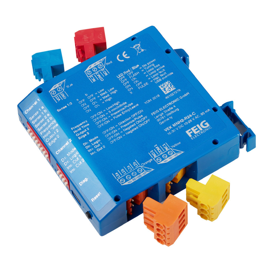
Signal outputs for controller • Relay output 2 (red, R24 variant) • Open collector output 2 (green, O24 variant) AC/DC connection (blue) Connections for power supply Tab. 5: VEK MNH Traffic Detector VEK MNH Operating Manual v1.3 en 16 | 56... -
Page 17: Technical Data
12 ms (independent of loop channels) Maximum speed for vehicles • presence detection Max. 200 km/h • direction detection (dual-channel variants) Max. 200 km/h (at loop head distance of 2 m) VEK MNH Operating Manual v1.3 en 17 | 56... - Page 18 Relays with contacts that are prestressed in this manner can only reliably switch currents over 100 mA! 3) Terminal block data Grid dimension 5.0 mm, conductor cross-section 0.25 - 2.5 mm², AWG 24-12 VEK MNH Operating Manual v1.3 en 18 | 56...
-
Page 19: Product Description
8-pole DIP switch for configuration • 4-pole DIP switch for configuration • USB diagnostic interface • Reset button • 24 V supply voltage • TS35 DIN rail mounting • Plastic housing Tab. 7: Product variants VEK MNH Operating Manual v1.3 en 19 | 56... -
Page 20: Product Characteristics
Comprehensive diagnostic function with Detector Tool Advanced functions of the dual-channel variants: • Output as presence, pulse or direction signal (dual-channel variant) or loop faults (with Detector Tool) • Selection of direction logic VEK MNH Operating Manual v1.3 en 20 | 56... -
Page 21: Vehicle Detection
When one loop channel is switched off by the Detector Tool, this does not affect the second, connected loop channel (2 channel versions). VEK MNH Operating Manual v1.3 en 21 | 56... -
Page 22: Description Of Connections
The induction loops are connected to the orange terminal blocks as shown in the illustration. Induction loop channel 1 connections Induction loop channel 2 connections (dual-channel variants) Fig. 5: Loop connections (orange) VEK MNH Operating Manual v1.3 en 22 | 56... -
Page 23: Signal Outputs
VEK MNH Description of connections Signal outputs VEK MNH series detectors are available in variants with relay outputs (R24) and with open collector bipolar transistors (O24). The relay variants are intended particularly for situations which require mechanical switches with high power outputs. -
Page 24: Open Collector Outputs
Object detection channel 1 Object detection channel 2 Fault indication channel 1 Fault indication channel 2 GNDoc Ground (emitter) Fig. 7: Open collector connections 1-2 and 3-4 (green) VEK MNH Operating Manual v1.3 en 24 | 56... -
Page 25: Assembly And Electrical Installation
5. Tighten the screw. 6. If necessary, insert the terminal block back into the blue 2-pole socket. The power cable is firmly attached to the terminal block with no exposed wires. VEK MNH Operating Manual v1.3 en 25 | 56... -
Page 26: Connect The Relay Outputs (Versions -R24)
1. Comply with the warning and safety instructions for the external device. 2. Follow the manufacturer’s instructions on wiring the outputs on the external device. The relay outputs are connected to the signal outputs on the external device. VEK MNH Operating Manual v1.3 en 26 | 56... -
Page 27: Connecting The Induction Loops
4. Insert up to 5 mm of stripped cable into the slot on the side of the terminal block and fasten. 5. Tighten the screw. 6. If necessary, insert the terminal block back into the orange 4-pole socket. The induction loops are firmly attached with no exposed wires. VEK MNH Operating Manual v1.3 en 27 | 56... -
Page 28: Commissioning
1. Define the settings with the DIP switches. 2. Switch the power supply to the detector on. The VEK MNH series detectors automatically run a test of the induction loops as well as a frequency alignment. The detector is ready for operation when the blue LEDs are continuously lit. There is more information in the section on LED indicators. -
Page 29: 10 Description Of Functions
Fig. 8: LED display of loop frequency NOTE LED position The LEDs for the loop channel 1 are located at the top or side of the device, for loop channel 2 are in the middle. VEK MNH Operating Manual v1.3 en 29 | 56... -
Page 30: Dip Switch Settings
Output 2 Output signal 2 mode Edge 2 Output signal 2 time Inv. Out 1 Output signal 1 inversion Inv. Out 2 Output signal 2 inversion Tab. 11: DIP switch assignment (default) VEK MNH Operating Manual v1.3 en 30 | 56... - Page 31 Loop 2 sensitivity Frequency Frequency level Hold time Hold time until readjustment Output 2 Output signal 2 mode Edge 2 Output signal 2 time Tab. 13: DIP switch 1 assignment (standard) VEK MNH Operating Manual v1.3 en 31 | 56...
- Page 32 Inv. Out 1 not inverted not inverted Inv. Out 2 inverted Presence Dir. Mode Direction Continuous signal 2 Dir. Logic Wrong-way driver 1 Tab. 15: Settings via DIP switch (dual-channel) VEK MNH Operating Manual v1.3 en 32 | 56...
-
Page 33: Reset Button
VEK MNH Operating Manual v1.3 en 33 | 56... - Page 34 VEK MNH Description of functions The following illustration shows the process of loop detuning by vehicles. Fig. 9: Detector Tool diagnostic view VEK MNH Operating Manual v1.3 en 34 | 56...
-
Page 35: 11 Description Of Settings
This document refers to the default settings or default values defined by the manufacturer. The factory settings of customer variants may differ from the manufacturer’s specifications. Please observe the instructions on the device, as well as the documents supplied with it. VEK MNH Operating Manual v1.3 en 35 | 56... -
Page 36: Adjusting Sensitivity (Switch-On Threshold)
… 0.15% 0.16% Level medium-low 0.17% … … 0.63% 0.64% level medium-low (factory setting) 0.65% … … 1000 1.00% … … 2550 2.55% Level minimum (lowest sensitivity) Tab. 17: Sensitivity settings VEK MNH Operating Manual v1.3 en 36 | 56... -
Page 37: Setting Hysteresis (Switch-Off Threshold)
Switch-off threshold (hysteresis in % of the switch-on Detector Tool (hysteresis) threshold) 20 % minimal (low switch-off threshold) … … 75 % (factory setting) … … 80 % maximum (high switch-off threshold) Tab. 19: Hysteresis settings VEK MNH Operating Manual v1.3 en 37 | 56... -
Page 38: Setting Loop Frequency (Frequency Step)
In the event of loop inductivity outside the recommended range, the available frequency range may be restricted. DIP (frequency) Detector Tool Frequency step low (factory setting) High High none (loop channel switched off) Tab. 20: Loop frequency settings VEK MNH Operating Manual v1.3 en 38 | 56... -
Page 39: Setting Hold Time
… 5 min … … 255 min Tab. 21: Hold time settings (VEK MNH) 11.5 Setting output mode (signal type) Various output modes (signal types) can be set for the outputs. WARNING Switching off the direction logic (2 channel version) The direction logic must be switched off to set the output mode, i.e. -
Page 40: Inverting Output Signal (Signal Behaviour)
A loop channel or a travel direction can be assigned to each output when direction detection is activated (dual-channel variants only). NOTE Settings in the Detector Tool The settings can be changed in the Detector Tool. VEK MNH Operating Manual v1.3 en 40 | 56... -
Page 41: Setting Output Switching Time (Impulse Time)
Switch-on delay with short loop coverage If the loop becomes free before the switch-on delay has expired, no signal is output. Settings with the Detector Tool The settings can only be changed with the Detector Tool. VEK MNH Operating Manual v1.3 en 41 | 56... -
Page 42: Setting Direction Detection (Dual-Channel Variants)
The direction logic generates logical output signals that are given out over the outputs depending on the setting. Parallel to this, the detector autonomously counts the logic signals. Fig. 12: Direction detection principle VEK MNH Operating Manual v1.3 en 42 | 56... - Page 43 65,535 (2 ) and is automatically erased. • The counter readings are not protected against power failure! Detector Tool Direction detection Switched off (factory settings) Switched on Tab. 30: Setting direction detection VEK MNH Operating Manual v1.3 en 43 | 56...
-
Page 44: Setting Direction Logic (Dual-Channel Variants)
Manoeuvring should not 200 ms) occur. Correct behaviour in the case of Feig Leaving Loop 1 queues and manoeuvring. Recording single vehicles and Loop free Leaving Loop 2 manoeuvring. Queues should not occur. VEK MNH Operating Manual v1.3 en 44 | 56... -
Page 45: Single Vehicle" Direction Logic
Tab. 33: Key to direction logic You can find information on the detailed functions for different traffic situations in the following section. 11.12.1 ”Single vehicle” direction logic Fig. 13: Single vehicle direction logic VEK MNH Operating Manual v1.3 en 45 | 56... -
Page 46: Queue" Direction Logic
VEK MNH Description of settings 11.12.2 ”Queue” direction logic Fig. 14: Queue direction logic 11.12.3 ”Wrong-way driver” 1 direction logic Fig. 15: Wrong-way driver 1 direction logic VEK MNH Operating Manual v1.3 en 46 | 56... -
Page 47: Wrong Way Driver 2" Direction Logic
VEK MNH Description of settings 11.12.4 ”Wrong way driver 2” direction logic Fig. 16: Wrong-way driver 2 direction logic 11.12.5 ”Manoeuvring” 1 direction logic Fig. 17: Manoeuvring 1 direction logic VEK MNH Operating Manual v1.3 en 47 | 56... -
Page 48: Manoeuvring" 2 Direction Logic
VEK MNH Description of settings 11.12.6 ”Manoeuvring” 2 direction logic Fig. 18: Manoeuvring 2 direction logic 11.12.7 ”Wrong-way driver in queue” direction logic Fig. 19: “Wrong-way driver in queue” direction logic VEK MNH Operating Manual v1.3 en 48 | 56... -
Page 49: Direction Logic „Cross Traffic
Fig. 20: Cross traffic direction logic NOTE False counts All logics except logic PB in direction 1 deliver false counts in this traffic situation, because they count entries instead of exits! VEK MNH Operating Manual v1.3 en 49 | 56... -
Page 50: Direction Logic „Parking Bay
Correct counting also with cross traffic • Correct counting with queues • Correct counting also when a single vehicle is manoeuvring • No manoeuvring is permitted to take place in a queue! VEK MNH Operating Manual v1.3 en 50 | 56... -
Page 51: 12 Maintenance & Servicing
7. Pull the cable out of the mounting slots. The detector is disassembled. At the end of its service life, dispose of the product in accordance with the valid legal specifications. VEK MNH Operating Manual v1.3 en 51 | 56... -
Page 52: 14 Key Words
Frequency alignment .......... 33 Output signals ............ 46 Frequency step ........... 42 Output time behaviour........46 Fresh alignment ..........24 Outputs ..........18, 26, 44 Functions ............40 Parking bay ..........48, 53 VEK MNH Operating Manual v1.3 en 52 | 56... - Page 53 Setting output mode ..........43 Settings ..........18, 35, 37, 40 Vehicle detection ..........24 Short circuit ............24 Signal behaviour ..........44 Wrong-way driver ......... 48, 50 Signal output ............26 VEK MNH Operating Manual v1.3 en 53 | 56...
-
Page 54: 15 Appendix
2.0 m USB cable type A to mini AB Tab. 35: separately available accessories 15.2 Declaration of conformity The EU Declaration of Conformity is available on the Internet at the following address: https://www.feig.de/downloads/ VEK MNH Operating Manual v1.3 en 54 | 56... - Page 55 VEK MNH Appendix Abb. 22: EU Declaration of Conformity VEK MNH Operating Manual v1.3 en 55 | 56...
- Page 56 VEK MNH Appendix VEK MNH Operating Manual v1.3 en 56 | 56...
Need help?
Do you have a question about the VEK MNH and is the answer not in the manual?
Questions and answers