Table of Contents
Advertisement
Advertisement
Table of Contents

Subscribe to Our Youtube Channel
Related Manuals for Feig Electronic VEK S4


Summary of Contents for Feig Electronic VEK S4
- Page 1 VEK S4 Manual VEK S4 Traffic Detector - 2009-03-31 S4_Handbuch_GB_090331.doc...
- Page 2 Photocopying and reproduction of this guide in whole or in part as well as translation into other languages is not permitted without prior written permission from FEIG ELECTRONIC. Also prohibited is storage of this guide in whole or in part on modern storage devices for the purposes of further processing in data processing systems.
-
Page 3: Table Of Contents
Manual VEK S4 Contents Functional Description ..........................4 Vehicle detection..........................5 Compensation ............................. 5 Classification of vehicles ........................5 Possible outputs..........................6 Multiplexing methods .......................... 6 Synchronisation........................... 6 Settings ..............................8 Frequency selection ..........................8 Multiplexing sequence......................... 8 Classification ............................8 Output modes............................ -
Page 4: Functional Description
VEK S4 Functional Description The VEK S4 traffic detector is a dual system for the inductive detection of vehicles. Information about the speed, length and class of a vehicle can be provided using the measuring system (two loop principle) and its evaluation. -
Page 5: Vehicle Detection
Longer calibration times are caused by frequency instabilities; their causes must be determined and remedied. 1.3 Classification of vehicles The VEK S4 detector has two classification modules for the vehicle recording. These can be parameterised independently from each other. 1.3.1... -
Page 6: Possible Outputs
Manual VEK S4 1.3.4 Tailgating If a vehicle is driving to close to the car in front a dummy vehicle (Other, l = 4.5 m, v= last vehicle) is reported with the vehicle speed of the car in front. Note: A correct detection of driving direction is not guaranteed for all tailgating situations. - Page 7 Manual VEK S4 VEK M4D Induction loops on multiple detectors a) Example without synchronization: Loop 2 of Detector Nr. 3 can in the worst case affect all the loops of Detectors 1,2,4 and themselves be affected by these loops. VEK M4D...
-
Page 8: Settings
For long loop supply lines it is recommended to use band 2..4 for frequency setting. If automatic frequency setting is activated, the VEK S4 uses the device address to choose one of the frequency range above. Please check the real frequency, because it can differ from the nominal frequency. - Page 9 Manual VEK S4 • Amplitude factor The loss of sensitivity due to abnormal loop dimensions, long loop lines or road surface reinforcements is largely compensated for using the amplitude factor. Automatic evaluation of this factor is also available. • Length adjustment The measured vehicle length is corrected with the length adjustment.
-
Page 10: Output Modes
Manual VEK S4 2.4 Output modes The following output modes can be set for the four open collector outputs: Output mode Description Standard output Normal output mode for presence or direction detection Group fault message Output indicates loop faults from all loops... -
Page 11: Rs485 Interface
The VEK S4 is downwards compatible with the interface protocols defined for the VEK S3. The protocols based on the TLS defined in the VEK S3 are also supported. In these cases, one VEK S4 behaves like two separately addressable VEK S3 units. Mixed operation of VEK S3 and VEK S4 on a common bus is not recommended. -
Page 12: Starting Up
Manual VEK S4 Starting up 1. Installation – The installation rail must be grounded. 5 Case and 7.5 PE connection 2. Address – The detector address is set to 48 at the factory using the address offset. All detectors which will be operated on a common interface must be set to different addresses before the commissioning. - Page 13 Manual VEK S4 11. Length adjustment – The displayed and actual lengths of a known vehicle must be compared and adjusted using the length adjustment. The adjustment of the speed and length measurements should be made with reference to average values obtained from several measuring cycles.
-
Page 14: Display And Operation
Manual VEK S4 Display and Operation 4.1 Display elements The front panel of the detector contains 4 green LEDs for indicating the respective loop state. LED behavior in normal operation: Description Loop free Loop busy or direction pulse flashes slowly... -
Page 15: Factory Settings
Manual VEK S4 4.3 Factory settings To restore the factory default parameters, proceed as follows: 1) Press button 6x briefly until shows on the LEDs. 2) Hold button down After one second all LEDs flash rapidly. After two seconds the LEDs go out. -
Page 16: Synchronisation Display
Manual VEK S4 4.4 Synchronisation display Correct function of the synchronization of multiple detectors is indicated by the scrolling effect of the LEDs in an 8s rhythm. As the device address increases from left to right, the scrolling LEDs also run from left to right for all synchronized detectors. - Page 17 Manual VEK S4 4.5.2 RS485 interface bus termination Typical wiring of the RS485 interface 470Ω 120Ω 120Ω ..470Ω Station The shown resistors are mounted inside the detector and switch able by the help of the DIP-switches...
-
Page 18: Case
Manual VEK S4 Case 5.1 Dimensions 03/09 FEIG ELECTRONIC GmbH... -
Page 19: Opening The Case
Manual VEK S4 5.2 Opening the case Opening : Loosen upper section A by gently pressing with a screwdriver on the side springs at B. Remove upper section. Closing: Check orientation, note contact surface C and PE contact D Guide circuit board into rear slot... -
Page 20: Technical Data
Manual VEK S4 Technical data Supply voltage: 12 to 24 V DC +/- 20 % SELV, limited power sources according to EN 60950-1 Power consumption: typ. 900 mW, max. 1,2 W Ambient temperature: -20 °C to +70 °C Storage temperature: -40 °C to +85 °C... -
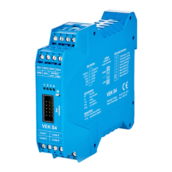
Page 21: Connector And Pin Assignment
Manual VEK S4 Connector and pin assignment Plug terminal Outputs 1 to 4 Plug terminal GND, 12..24V, Interface Low / High OC1 OC2 OC3 OC4 Interface GND 24V High 1 2 3 4 Bus connection via ribbon cable VEK M4D... -
Page 22: Loop Connections
PE contact spring D of the enclosure! The DIN rail must be connected to PE in the system with low impedance ! Noise immunity of the VEK S4 cannot be guaranteed without a PE connection to the DIN rail ! 03/09... -
Page 23: Standard Equipment, Accessories
For additional connections or as a spare part for the loop connections 8.3 Service software The traffic detector can be parameterised using the S4Com service program. As the VEK S4 is downwards compatible and supports the interface protocols of the VEK S3, the S3ComWin service program can also be used. -
Page 24: Safety Instructions And Warnings
Manual VEK S4 Safety instructions and warnings • The device may be used only for the purpose intended by the manufacturer. • This manual must be kept in an accessible place and handed out to each user. • Improper modifications and use of replacement parts and add-on equipment not purchased or recommended by the manufacturer may cause fire, electrical shock and injury. -
Page 25: 10 4-Channel Functions
VEK S4 10 4-channel functions The VEK S4 detector can also be used for presence detection with flexible direction recognition due to its integrated 4-channel functions (4Ch). The parameters for use as a presence detector are explained in this chapter. -
Page 26: Hysteresis Drop (4Ch)
2550 10.63 % lowest sensitivity Note: The response thresholds of the VEK S4 are different from the response threshold of the VEK M4D for the same sensitivity (∆ f/f). 10.3 Hysteresis drop (4Ch) In order to avoid an intermediate loss of the occupied signal for vehicles with a high undercarriage such as articulated buses, trams, trucks with trailers etc, it is possible to modify the switching hystereses. -
Page 27: Holding Time (4Ch)
Manual VEK S4 Detuning by vehicle Cut-in threshold Drop value threshold at 75% Drop value threshold at 25% Output signal for 75% drop value threshold Output signal Output signal for 25% drop value threshold 10.4 Holding time (4Ch) Separate holding times between 1 and 255 minutes can be set for each channel on the detector. A zero setting means infinite waiting time. -
Page 28: Direction Recognition (4Ch)
VEK S4 10.5 Direction recognition (4Ch) In addition to the simple direction recognition present in the classification modules, the VEK S4 detector has two parameterisable logic modules for the direction-dependent recording of vehicles. Complex evaluation algorithms using double loops are integrated in the detector. The direction logic generates logical output signals which can be output via a hardware output or via an interface depending on the setting. - Page 29 Manual VEK S4 Direction logic Signal output Signal waste Remark D1 - Continuous signal 1 left 1. loop Allocation 1. loop DB - Continuous signal Signal output in opposite direction takes place only both loops again if both loops were free before- left 2.
- Page 30 Manual VEK S4 10.5.1 Direction detection in various traffic situations Various traffic situations are shown in the following for Loops 1 and 2. The evaluation of the direction signal is performed in the same manner in the reverse direction of travel as well for Loops 3 and 4 or other loop combinations.
- Page 31 Manual VEK S4 10.5.1.2 Traffic line Ri1 Ri2 Imp Imp Imp Imp 10.5.1.3 Wrong-way driver 1 Ri1 Ri2 Imp Imp FEIG ELECTRONIC GmbH 03/09...
- Page 32 Manual VEK S4 10.5.1.4 Wrong-way driver 2 Ri1 Ri2 Imp Imp 10.5.1.5 Maneuverer 1 Ri1 Ri2 Imp Imp 03/09 FEIG ELECTRONIC GmbH...
- Page 33 Manual VEK S4 10.5.1.6 Maneuverer 2 Ri1 Ri2 Imp Imp Imp Imp FEIG ELECTRONIC GmbH 03/09...
- Page 34 Manual VEK S4 10.5.1.7 Wrong-way driver in traffic line Ri1 Ri2 Imp Imp 10.5.1.8 Cross-traffic Ri1 Ri2 Imp Imp All logics except for PB in Direction 1 will result in incorrect counts in this traffic situation, since they count in instead of out.
- Page 35 Manual VEK S4 10.5.2 Direction logic „Parking Bay“ This direction logic is used for short entrances and exits. This logic suppresses compromising of the count by cross-traffic on Loop 1. This means it is non-critical whether Loop 1 is placed in the passing lane or in the maneuvering area.
-
Page 36: Notes
Manual VEK S4 11 Notes 03/09 FEIG ELECTRONIC GmbH...
Need help?
Do you have a question about the VEK S4 and is the answer not in the manual?
Questions and answers