Table of Contents
Advertisement
Available languages
Available languages
Quick Links
VEK MNH1-R24-A
DE - Kurzanleitung
HINWEIS
Betriebsanleitung lesen
Detaillierte Anweisungen und ausführliche Informationen finden Sie in
der vollständigen Betriebsanleitung zum Produkt. Das Dokument steht
auf der Homepage des Herstellers unter
HINWEIS
Anleitung lesen und aufbewahren
Lesen Sie das Dokument vor der ersten Verwendung des Produkts
und bewahren Sie es für späteres Nachschlagen auf!
HINWEIS
Wartung und Reparaturen
Für dieses Produkt ist keine Wartung und Instandhaltung erforderlich.
Bei Störungen und Defekten wenden Sie sich bitte an den Verkäufer
oder Hersteller.
ACHTUNG
Unsachgemäße Verwendung
Für das Gerät gelten die Gewährleistungsbestimmungen des
Herstellers in der zum Zeitpunkt des Kaufs gültigen Fassung. Für eine
ungeeignete, falsche manuelle oder automatische Einstellung von
Parametern für ein Gerät bzw. ungeeignete Verwendung eines
Gerätes wird keine Haftung übernommen.
Unzulässige Reparaturen
Reparaturen dürfen nur vom Hersteller durchgeführt werden. Bei
Zuwiderhandeln ist die Sicherheit gefährdet und führt zu einem Verfall
der Gewährleistung.
Zulässige Spannungsquellen
Die Spannungsversorgung muss die Anforderungen für
Schutzkleinspannungen (SELV, „Stromkreise und Stromquellen
begrenzter Leistung") erfüllen.
Erforderliche Sicherheitseinrichtungen
Das Gerät darf nicht als Sicherheitsbauteil im Sinne der
Maschinenrichtlinie 2006/42/EG, der Bauproduktenverordnung
305/2011/EU oder anderer Sicherheitsvorschriften verwendet werden.
In Anlagen mit Gefährdungspotential sind zusätzliche
Sicherheitseinrichtungen erforderlich!
Das Produkt am Ende seiner Lebensdauer gemäß den
geltenden gesetzlichen Bestimmungen entsorgen.
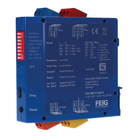
1 Produktübersicht
Produktbestandteile
Verkehrsdetektor VEK MNH1-R24-A
Steckklemmenblöcke: 1x Versorgung, 1x Schleifen, 2x Relais
Kurzanleitung
Tab. 1: Lieferumfang
VEK MNH1-R24-A KURZANLEITUNG 1.4 DE
www.feig.de
zur Verfügung.
Abb. 1: Verkehrsdetektor VEK MNH1-R24-A
Index Komponente
A
DIP-Schalter
B
Schleifenkanal LEDs (rot + blau)
C
USB-Anschluss
D
Reset-Taste
E
Schleifeneingang (orange)
F
Relais-Ausgang 1 (gelb)
Montagevorrichtung für DIN-Schiene TS35 („Hutschiene")
G
H
Relais-Ausgang 2 (rot)
I
AC/DC-Anschluss (blau)
Tab. 2: Komponentenliste VEK MNH1-R24-A
Technische Daten
Abmessungen
Spannungsversorgung
(1x blau, 2-polig)
Schutzart
zulässige Betriebstemperatur
relative Luftfeuchtigkeit
Schleifeneingang
•
max. Induktivitätsbereich
•
empfohlener
Induktivitätsbereich
•
Arbeitsfrequenz
•
max. Zuleitungslänge
•
max. Innenwiderstand
Signalausgänge
•
2x Relais
Konfigurationsschalter
LED Statusanzeige
Reset
1 | 4
22,5 x 79,0 x 81,0 mm (BxHxL, ohne
Klemmen)
10 – 30 VDC / 10 – 26 VAC,
max. 2 W (SELV)
IP20
-37 – +70 °C
< 95 % (nicht betauend)
1x orange, 2-polig
20 – 700 H (siehe Hinweis 1)
100 – 300 H
30 – 130 kHz
200 m
20 Ω (einschließlich Zuleitung)
1x gelb + 1x rot, je 3-polig
max. 48 V (AC/DC), 2 A, 60 W,
125 VA (SELV)
min. 1 mA / 5 V (siehe Hinweis 2)
8-poliger DIP-Schalter
1x blau + 1x rot
Drucktaster
SENSORS
Advertisement
Table of Contents

Related Manuals for Feig Electronic VEK MNH1-R24-A


Summary of Contents for Feig Electronic VEK MNH1-R24-A
- Page 1 Für dieses Produkt ist keine Wartung und Instandhaltung erforderlich. Bei Störungen und Defekten wenden Sie sich bitte an den Verkäufer oder Hersteller. ACHTUNG Abb. 1: Verkehrsdetektor VEK MNH1-R24-A Unsachgemäße Verwendung Für das Gerät gelten die Gewährleistungsbestimmungen des Index Komponente Herstellers in der zum Zeitpunkt des Kaufs gültigen Fassung. Für eine...
-
Page 2: Beschreibung Der Anschlüsse
• Hysterese (Abfallschwelle) einstellbar von 20 – 80 % je Kanal mit Detector Tool Tab. 4: Schaltzustände der Signalausgänge • Detektorkanäle abschaltbar mit Detector Tool • Umfangreiche Diagnosefunktionen mit Detector Tool SENSORS VEK MNH1-R24-A KURZANLEITUNG 1.4 DE 2 | 4... -
Page 3: Beschreibung Der Funktionen
Zeitpunkt Ausgangssignal 2 Inv. Out 1 Invertierung Ausgangssignal 1 Blinkcode der LEDs nach einem Frequenzabgleich Inv. Out 2 Invertierung Ausgangssignal 2 Tab. 8: Belegung DIP-Schalter (Standard) Abb. 5: LED-Wiedergabe der Schleifenfrequenz SENSORS VEK MNH1-R24-A KURZANLEITUNG 1.4 DE 3 | 4... -
Page 4: Usb-Schnittstelle
Über die USB-Schnittstelle sind die detaillierte Konfiguration sowie die Diagnose der Detektordaten möglich. Das kostenlose Serviceprogramm Detector Tool kann im Kundenbereich www.feig.de heruntergeladen werden. Zusätzlich wird ein Computer sowie ein USB-Kabel vom Typ Mini-AB benötigt. SENSORS VEK MNH1-R24-A KURZANLEITUNG 1.4 DE 4 | 4... -
Page 5: Product Overview
48 V (AC/DC), 2 A, 60 W, 125 VA (SELV) min. 1 mA / 5 V (see note 2) Configuration switch 8-pole DIP switch LED status indicator 1x blue + 1x red SENSORS VEK MNH1-R24-A QUICK START GUIDE 1.4 EN 1 | 4... -
Page 6: Product Description
Tab. 4: Switching states of the signal outputs each channel with Detector Tool • Detector channels can be switched off with Detector Tool • Comprehensive diagnostic function with Detector Tool SENSORS VEK MNH1-R24-A QUICK START GUIDE 1.4 EN 2 | 4... -
Page 7: Description Of Functions
Output signal 2 time Inv. Out 1 Output signal 1 inversion Inv. Out 2 Output signal 2 inversion Fig. 5: LED display of loop frequency Tab. 8: DIP switch assignment (default) SENSORS VEK MNH1-R24-A QUICK START GUIDE 1.4 EN 3 | 4... -
Page 8: Usb Interface
The free Detector Tool service program can be downloaded from the customer area at www.feig.de. In addition, a computer and a USB cable of the Mini-AB type are required. SENSORS VEK MNH1-R24-A QUICK START GUIDE 1.4 EN 4 | 4... - Page 9 2x relais max. 48 V (AC/DC), 2 A, 60 W, 125 VA (SELV) min. 1 mA / 5 V (voir remarque 2) Interrupteur de configuration Interrupteur DIP 8 pôles SENSORS VEK MNH1-R24-A GUIDE DE DÉMARRAGE RAPIDE 1.4 FR 1 | 4...
-
Page 10: Description Des Raccordements
Retard d’activation et de désactivation réglable avec le Detector Tool 3.3.1 Sorties de relais avec contact inverseur • Hystérèse (seuil de chute) réglable de 20 à 80 % par canal avec le Detector Tool SENSORS VEK MNH1-R24-A GUIDE DE DÉMARRAGE RAPIDE 1.4 FR 2 | 4... -
Page 11: Touche De Réinitialisation
Logique d’évaluation de la direction du Logique de direction allumé déplacement selon le cas d’application lorsque la boucle est occupé (voir instruction de service clignote Fréquence complète!) Tab. 7: Descriptions des raccordements SENSORS VEK MNH1-R24-A GUIDE DE DÉMARRAGE RAPIDE 1.4 FR 3 | 4... - Page 12 Le programme de service gratuit Detector Tool peut être téléchargé à partir de l'espace client sur www.feig.de. De plus, un ordinateur et un câble USB de type Mini-AB sont nécessaires. SENSORS VEK MNH1-R24-A GUIDE DE DÉMARRAGE RAPIDE 1.4 FR 4 | 4...
-
Page 13: Es - Guía De Inicio Rápido
1x amarillo + 1x rojo, de 3 polos correspondientemente • 2x relé máx. 48 V (CA/CC), 2 A, 60 W, 125 VA (SELV) mín. 1 mA/5 V (véase indicación 2) SENSORS VEK MNH1-R24-A-NWD Guía de inicio rapido 1.4 es 1 | 4... -
Page 14: Descripción Del Producto
(umbral de caída) ajustable de 20-80 % por cada canal con Detector Tool • canales de detector desconectables con Detector Tool • amplias funciones de diagnóstico con Detector Tool 3 Descripción de las conexiones SENSORS VEK MNH1-R24-A-NWD Guía de inicio rapido 1.4 es 2 | 4... -
Page 15: Ajustes De Interruptores Dip
Inversión de salida de señal 1 Inv. Out 2 Inversión de salida de señal 2 Tab. 8: Asignación de interruptores DIP (estándar) Fig. 5: Reproducción LED de la frecuencia de bucle SENSORS VEK MNH1-R24-A-NWD Guía de inicio rapido 1.4 es 3 | 4... -
Page 16: Interfaz Usb
El programa de servicio gratuito Detector Tool se puede descargar desde el área de clientes en www.feig.de. Además, se necesita un ordenador y un cable USB del tipo Mini-AB. SENSORS VEK MNH1-R24-A-NWD Guía de inicio rapido 1.4 es 4 | 4... -
Page 17: Panoramica Del Prodotto
In caso di guasti o di difetti, si prega di rivolgersi al rivenditore o al produttore. ATTENZIONE Fig. 1: Rilevatore di traffico VEK MNH1-R24-A Uso non conforme Index Elemento Per l'apparecchio vigono le informative sulla responsabilità del Interruttore DIP produttore nella versione valida al momento dell'acquisto. -
Page 18: Alimentazione Di Tensione
(soglia di diseccitazione) regolabile da 20 – 80 % per ogni canale col Detector Tool • canali del rilevatore disattivabili col Detector Tool • funzioni diagnostiche complete con il Detector Tool 3 Descrizione dei collegamenti SENSORS VEK MNH1-R24-A GUIDA RAPIDA 1.4 IT 2 | 4... -
Page 19: Descrizione Delle Funzioni
Legenda dei simboli LED in base alla modalità di applicazione e con occupazione del loop (vedere le istruzioni per illuminato spento l’uso complete!) lampeggiante Frequenza Tab. 7: Descrizione delle impostazioni SENSORS VEK MNH1-R24-A GUIDA RAPIDA 1.4 IT 3 | 4... -
Page 20: Interfaccia Usb
USB. Il programma gratuito di assistenza Detector Tool può essere scaricato dall'area clienti all'indirizzo www.feig.de. Inoltre, sono necessari un computer e un cavo USB del tipo Mini-AB. SENSORS VEK MNH1-R24-A GUIDA RAPIDA 1.4 IT 4 | 4... - Page 21 Voor dit product zijn geen onderhoud en revisie noodzakelijk. Neem bij storingen of defecten contact op met de verkoper of fabrikant. LET OP! Afb. 1: Verkeersdetector VEK MNH1-R24-A Oneigenlijk gebruik Voor het apparaat gelden de garantiebepalingen van de fabrikant in de Index Component op het moment van aankoop geldige versie.
-
Page 22: Beschrijving Van De Aansluitingen
Hysterese (gevoeligheid) van elk kanaal instelbaar tussen 20 – 80 % met het Detector Tool • Detectorkanalen kunnen worden uitgeschakeld met het Detector Tool • Uitgebreide diagnosefuncties met het Detector Tool 3 Beschrijving van de aansluitingen SENSORS VEK MNH1-R24-A SNELSTARTGIDS 1.4 NL 2 | 4... -
Page 23: Beschrijving Van De Functies
Tab. 5: Signaalkleuren van de leds Richtingslogica Analyselogica voor de rijrichting naar gelang de toepassing bij lusbelasting (zie de volledige Legenda led-symbolen handleiding!) brandt Tab. 7: Beschrijving van de instellingen knippert frequentie SENSORS VEK MNH1-R24-A SNELSTARTGIDS 1.4 NL 3 | 4... -
Page 24: Usb Interface
Gedetailleerde configuratie en diagnose van de detectorgegevens zijn mogelijk via de USB-interface. Het gratis serviceprogramma Detector Tool kan worden gedownload van www.feig.de de klantenpagina op . Daarnaast zijn een computer en een USB-kabel van het type Mini-AB nodig. SENSORS VEK MNH1-R24-A SNELSTARTGIDS 1.4 NL 4 | 4... - Page 25 Maks. 48 V (AC/DC), 2 A, 60 W, 125 VA (SELV) Min. 1 mA / 5 V (se henvisning 2) Konfigurationskontakt 8-polet DIP-kontakt LED-statusvisning 1x blå + 1x rød SENSORS VEK MNH1-R24-A Quick start guide 1.4 da 1 | 4...
- Page 26 Indkoblings- og udkoblingsforsinkelse indstillelig med Detector Tool • Hysterese (udfaldstærskel) indstillelig 20–80% for hver kanal med Detector Tool • Detektorkanaler kan frakobles med Detector Tool • Omfattende diagnosefunktioner med Detector Tool SENSORS VEK MNH1-R24-A Quick start guide 1.4 da 2 | 4...
- Page 27 Modus udgangssignal 2 Edge 2 Tidspunkt udgangssignal 2 Inv. Out 1 Invertering udgangssignal 1 Inv. Out 2 Invertering udgangssignal 2 Fig. 5: LED-gengivelse af sløjfefrekvens Tab. 8: Okkupering DIP-kontakt (standard) SENSORS VEK MNH1-R24-A Quick start guide 1.4 da 3 | 4...
- Page 28 Den detaljerede konfiguration og diagnosticering af detektordataene er mulige via USB-interface. Det gratis serviceprogram Detector Tool kan downloades i kundeområdet på www.feig.de. Derudover kræves en computer og et Mini-AB USB- kabel. SENSORS VEK MNH1-R24-A Quick start guide 1.4 da 4 | 4...
Need help?
Do you have a question about the VEK MNH1-R24-A and is the answer not in the manual?
Questions and answers