Graco PR70 Instructions Manual
Hide thumbs
Also See for PR70:
- Operation & maintenance manual (82 pages) ,
- Repair and parts manual (82 pages) ,
- Instructions - parts manual (74 pages)
Table of Contents
Advertisement
Quick Links
Instructions - Parts
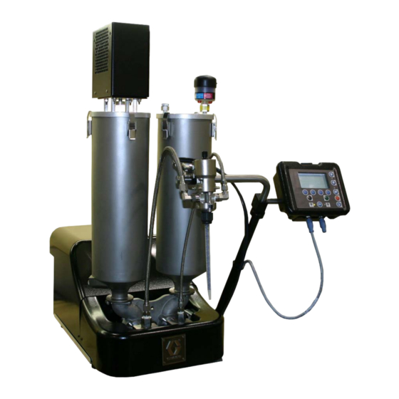
PR70 and PR70v
Feed Systems
Fixed or variable ratio systems. For accurate metering, mixing, and dispensing of
two-component materials.
3000 psi (21 MPa, 207 bar) Maximum Working Pressure
100 psi (0.7 MPa, 7 bar) Maximum Air Inlet Pressure
Important Safety Instructions
Read all warnings and instructions in all sup-
plied manuals. Save these instructions.
PR70v shown with Polyethylene Tanks
312394C
ti12580a
Advertisement
Table of Contents

Related Manuals for Graco PR70


Summary of Contents for Graco PR70
- Page 1 Instructions - Parts PR70 and PR70v Feed Systems 312394C Fixed or variable ratio systems. For accurate metering, mixing, and dispensing of two-component materials. 3000 psi (21 MPa, 207 bar) Maximum Working Pressure 100 psi (0.7 MPa, 7 bar) Maximum Air Inlet Pressure...
-
Page 2: Table Of Contents
Ball Valve Repair ......23 Graco Information ......68 Agitator Fuse Replacement . -
Page 3: Supplied Manuals
Assemblies with a Standard Display Module will not include manuals 312759 and 312760. Assemblies with an Advanced Display Module will not include manual 312393. PR70 and PR70v Operation and Parts Manuals Part Description 312393 PR70 with Standard Display Module Operation and... -
Page 4: Product Configurator
PR70B - J - A5 - A5 - E - A6 - A6 - 3 - 1 - 2 - A - N - 3 - N - H - N - 6 - N - Y - N Code: The following part number fields apply for the PR70 and PR70v part numbering configurator fields. Shaded items listed in the configurator table below are “Super Standard” items that are typically stocked and provide the best deliv- ery dates. - Page 5 Product Configurator Custom Low Volume side, consult fac- tory (stainless steel only) Code F Part Controls LC0274 Advanced Display Module with 1 Fluid Control Module LC0275 Advanced Display Module with 2 Fluid Control Modules LC0298 Standard Display Module Codes G-H, High Volume Hose / Part Low Volume Hose...
- Page 6 Product Configurator LC0169 Recirculating, On-Board Tanks, LC0197 Recirculating, Heated, On-Board 3/8 in. (9.5 mm) - 15 ft (4.6 m) Tanks, 1/2 in. (13 mm) - 10 ft (3.0 m) LC0170 Recirculating, On-Board Tanks, LC0198 Recirculating, Heated, On-Board 1/2 in. (13 mm) - 2.5 ft (0.6 m) Tanks, 1/2 in.
- Page 7 Product Configurator LC0157 8 L, Twin Polyethylene Tanks and Lids, Code M Part Applicator Mounting Two Pneumatic Agitator LC0294 None, Customer Mount Controls and LC0158 8 L, Twin Polyethylene Tanks and Lids, Applicator One Pneumatic Agitator, with Shut-Off LC0292 Mast Mount, Controls & MD2 Applica- Valves tor Machine Mounted LC0159...
- Page 8 Product Configurator LC0237 7.5 L, Stainless Steel, High Level Sen- Code Q Part High Volume Side Tank Cover sors, LC0018 On-Board Dust Cover 240V Heat LC0019 On-Board Clamp Down LC0238 7.5 L, Stainless Steel, High Level Sen- LC0020 On-Board Vacuum De-gas sors, LC0021 On-Board Agitate 120VAC 50/60 Hz...
- Page 9 Off-Board Tank Stands Refill Logic None LC0281 7.5 L Stainless Steel - Low Level Sen- LC0103 PR70 Tank Stand sors Only, and 30 L or 60 L Stainless LC0247 PR70v Tank Stand Steel - Low Level Sensors Only LC0286 7.5 L Stainless Steel - Low Level Sen-...
-
Page 10: Warnings
Warnings Warnings The following warnings are for the setup, use, grounding, maintenance, and repair of this equipment. The exclama- tion point symbol alerts you to a general warning and the hazard symbol refers to procedure-specific risk. Refer back to these warnings. Additional, product-specific warnings may be found throughout the body of this manual where applicable. - Page 11 Warnings WARNING FIRE AND EXPLOSION HAZARD Flammable fumes, such as solvent and paint fumes, in work area can ignite or explode. To help prevent fire and explosion: • Use equipment only in well ventilated area. • Eliminate all ignition sources; such as pilot lights, cigarettes, portable electric lamps, and plastic drop cloths (potential static arc).
-
Page 12: Grounding
Grounding Grounding Products that include electric agitators, heated hoses, or heated tanks must be grounded. In the event of an elec- trical short circuit, grounding reduces the risk of electric shock by providing an escape wire for the electric cur- rent. -
Page 13: Installation
Installation Installation Polyethylene Tank Lid with 7. Attach appropriate hoses and cables. Agitator • For electric agitator models, plug the agitator The polyethylene tank lid o-ring is installed with Kry- power cable into one of the outlets in the incom- tox. -
Page 14: Level Sensors
Installation Level Sensors Stainless Steel Tanks Polyethylene Tanks 2102 2101 1. Install sensor (2001) using two screws (2003). The 2103 cable (2002) for the sensor should be pointing towards the center of the machine base. ti12494a 2104 2001 2003 1. Empty the tank. 2002 2. -
Page 15: Auto-Refill Installation
Installation Accumulators Auto-Refill Installation The Auto-Refill assembly is shipped uninstalled. The The accumulator level sensors (144) can be Auto-Refill assembly can be installed in multiple places installed on any side of the main cylinder (123). on the tanks. See F . -
Page 16: Startup
Startup Startup Pressure Relief Procedure 1. Locate power switch at rear of machine and turn power on. The display module will automatically turn on and begin to load. 1. Place a waste container below the dispense valve. 2. Slide the system air pressure relief switch up. It is 2. -
Page 17: Setup
Setup Setup Level Sensor Calibration Polyethylene Tank Sensor Diagnostics A solid red state does not indicate malfunction of Polyethylene Tanks the unit. It indicates that material level is a little above or below the sensor. State Action Description 2001 Unit is ready for opera- tion Flashes slow Sensor is self-adjust-... -
Page 18: Vacuum De-Gas
Setup Stainless Steel Tanks Vacuum De-gas This procedure is for assemblies with Vacuum Tree 2102 Manifold and No Agitator or Auto-Refill. See F . 5. 2101 1034 2103 1015 ti12494a 2104 1. Locate the calibration button on the sensor (2101) closest to the electrical connector through one of the four holes of the sensor well (2102). -
Page 19: Vacuum De-Gas And Vacuum Auto-Fill
Setup 11. Turn off the vacuum pump. the Auto-Refill Tank Select button ( ) if a valid Auto-Refill mode is enabled for both tanks. 12. Open the top ball valve of the vacuum tree manifold (1015). 10. Press the appropriate Auto-Refill Tank Select button CAUTION or buttons ( and/or... -
Page 20: Accumulator Filling
Accumulator air pressure should be set to the low- est possible setting to adequately run the accumu- lator. 8. See the PR70 and PR70v Operation manual refer- enced at the beginning of this manual to adjust dis- play module run settings for the accumulator. -
Page 21: Shutdown
Shutdown Shutdown If the machine is to remain idle for an extended period of time, perform the following steps. 1. Place a waste container below the dispense valve. 2. If installed, remove static mixer from the end of the dispense valve. 3. -
Page 22: Repair
Repair Repair Tank Removal 5. On models without ball valves, remove the tanks. • For polyethylene tank models, rotate the lock 1. On models without ball valves, empty tanks by ring (218) for each tank counter clockwise and executing multiple shots. lift the tanks off of the base. -
Page 23: Ball Valve Repair
Repair Stainless Steel Tanks 3. Reassemble and install the four screws that hold the ball valve assembly together. Follow ball valve removal from tank procedure in reverse order. 506a Agitator Fuse Replacement 506b 506c 506d Assembly 255284 Shown ti12453a ti12559a 1. - Page 24 Repair 312394C...
-
Page 25: Parts
Parts Parts Accumulators, Assemblies LC0160 and LC0297 Apply thread sealant tape to male npt threads prior to installation. 111, 121 ti12449a 312394C... - Page 26 Parts Accumulators, continued ti12472a Apply thread sealant tape to male npt threads prior to installation. 312394C...
- Page 27 Parts Part Description Part Description 95/0913/02 O-RING, ep, jbh 15T679 COVER, front, accumulator, (assembly LC0297 only) mild steel, PR70 95/0913/00 O-RING, fluoroelastomer, 01/1449/99 COVER, back, accumulator, jbh (assembly LC0160 only) mild steel 95/0605/01 SEAL, u-cup, 1/2 ID x 3/4 96/0282/98...
-
Page 28: Liter Polyethylene Tanks
Parts 8 Liter Polyethylene Tanks Assembly 255282 Shown ti12450a Apply thread sealant tape to male npt threads prior to installation. Do not attempt to remove from tank. Disassembling will damage tank. 312394C... - Page 29 Parts Quantity Part Description † * O-RING, fluoroelastomer, bbc 95/0223/00 † * O-RING 120902 SCREW, button head cap screw, M5 x 0.8 x 40 mm † * SCREW, socket head cap, M5 x 0.8 x 18 mm 120904 120905 NUT, HEX, lock M5 X 0.8 120906 NUT, HEX, lock M8 X 1.25 120907...
-
Page 30: Polyethylene Tank Agitators
Parts Polyethylene Tank Agitators Electric Agitator Assemblies 255246 and 255503 Shown for reference only. Assembly 255246 Shown ti12456a 312394C... - Page 31 Parts Part Description 01/2218/97 ENCLOSURE, agitator, electric, prmv/f, hd 01/2219/97 PLATE, adapter, electric agitator, hd, prm 81/2218-1/11 MOTOR, 50 rpm, 60 in-lb, 120V, 1.2A (assembly 255246 only) 256613 MOTOR, 50 rpm, 60 in-lb, 230V (assembly 255503 only) 81/1040/11 MODULE, ac, 2p, 250V, 10a, double pull sin- gle throw, w/fuse 81/1040-1/11 MODULE, ac connector, 2P, 250V, 10A, with...
- Page 32 Parts Pneumatic Agitator Assembly 255730 804, 811 Apply thread sealant tape to male npt threads prior to installation. Shown for reference only. ti12457a 312394C...
- Page 33 Parts Part Description 82/0216/11 MOTOR, motor, pneumatic, agitator, 0.32 hp 94/0838/96 VALVE, needle, 1/8 npt x 1/8 npt, male / female 01/1189/98 ADAPTER, coupling, air motor, agitator 5-01-0510 SCREW, socket head cap, 10-32 x 5/8 in. 84/2215-A/11 COUPLING, alignment, 1 in. OD, hub, 3/8 in.
- Page 34 Parts Agitator Shaft, 255724 ti12458a Part Description 01/2230-1/98 PADDLE, agitator, tfm tank, stainless steel 01/2230-2/98 SUPPORT, mount, paddle, agitator 96/0097/98 FASTENER, screw, socket head cap, 10-24 x 1.25, stainless steel 96/0125/98 FASTENER, screw, socket head cap, 10-24 x 0.50, stainless steel 96/0129/98 WASHER, flat, SAE, #10, stainless steel, 1/2 in.
- Page 35 Parts 312394C...
-
Page 36: On-Board Stainless Steel Tanks
Parts On-Board Stainless Steel Tanks Tank Assemblies LC0237, LC0238, LC0254, and LC0255 Right hand tank shown, left hand tank is mirror image. 304a Assembly LC0237 Shown ti12451a Use glass cloth tape to secure ground strap, thermal switch, and RTD to tank wall before adding heat blanket. Secure heat blanket to tank with string laced through eyelets. - Page 37 Parts Part Description LC0235 TANK, 7.5 L stainless steel, high level (assembly LC0237 only) LC0236 TANK, 7.5 L stainless steel, high level, shut-off (assembly LC0238 only) LC0012 TANK, 7.5 L stainless steel (assembly LC0254 only) 255284 TANK, 7.5 L stainless steel, shut-off (assembly LC0255 only) LC0861 BLANKET, heat, 7.5L tank, 220V...
- Page 38 Parts Tank Assemblies 255284, 255285, LC0235, LC0236, LC0012, and LC0013 It is recommended that the flat face of the tank faces the back of the base machine. Right hand tank shown, left hand tank is mirror image. 506a 506b 506c 506d ti12453a Assembly 255284 Shown...
-
Page 39: Ball Valve, Assembly 255280
Parts Ball Valve, Assembly 255280 2204a 2204b 2204c 2202 2201 2204h 2203 2204j 2205 2206 2204d 2204e ti12564a 2204f 2204g Part Description 2201 96/0075-1/99 WASHER, flat, sae, 7/16, mild steel, n series 2202 96/0075/99 WASHER, lock, split, 7/16, mild steel 2203 121012 SCREW, M8 x 1.25 65 mm, socket head cap screw, stainless steel... -
Page 40: On-Board Stainless Steel Tank Lids
Parts On-Board Stainless Steel Tank Lids Lid Assemblies LC0019 to LC0026 and LC00130 to LC00132 1017 Assembly LC0025 Shown 1018 1019 1027 1020 1028 1021 1015 1023 1009 1008 1021 1006 1034 1007 1024 1033 1025 1016 1026 1030 1016 1029 1016 1035... - Page 41 Parts Quantity Part Description 1005 15M392 TANK, modified 1006 95/0518/00 O-RING, fluoroelastomer, JJF 1007 96/0282/98 FASTENER, screw, button head cap screw, 8-32 x 0.38, stainless steel 1008 96/0820/98 CLAMP, over the center, stainless steel 1009 96/0176-1/98 NUT, lock, 8-32, nylock, stainless steel 1010 15M320 LID, 7L, 2 npt, 1 9/16-32 15M321...
- Page 42 Parts Lid Assembly LC0018 1303 1301 1304 1302 ti12461a Apply thread sealant tape to male npt threads prior to installation. Part Description 1301 15M956 LID, mod, 7.5L & 3L, stainless steel 1302 96/0127/98 FASTENER, socket head cap screw, 1/4-20 x 0.37, stainless steel 1303 96/0148/11 KNOB, 1/4-20, female, plastic...
-
Page 43: Off-Board Stainless Steel Tanks
Parts Off-Board Stainless Steel Tanks Tank Assemblies LC0054 and LC0055 Apply thread sealant tape to male npt threads prior to installation. ti12454a Assembly LC0054 Shown Part Description 94/0372/98 PLUG, socket head, 3/4 npt, stainless steel 94/0371/98 PLUG, socket head, 1/2 npt, stainless steel 95/0223/00 O-RING, fluoroelastomer, bbc 120904... - Page 44 Parts Tank Assemblies LC0259 and LC0260 Assembly LC0259 Shown ti12452a Use glass cloth tape to secure ground strap, thermal switch, and RTD to tank wall before adding heat blanket. Secure heat blanket to tank with string laced through eyelets. Insulation blanket should cover heat blanket completely. Secure insulation blanket to tank with 2 in.
- Page 45 Parts Pipe and Tube System, 255391 2806 Part Description 2808 LC0054 TANK, assy, 30 L, stainless steel 2805 (assembly LC0259 only) 2802 LC0055 TANK, assembly, 60 L, stainless 2804 steel 2801 (assembly LC0260 only) LC0257 BLANKET, assy, heat, 30L, 240V, (assembly LC0259 only) LC0258 BLANKET, assy, heat, 60L, 240V,...
-
Page 46: Off-Board Stainless Steel Tank Lids
Parts Off-Board Stainless Steel Tank Lids Lid Assembly LC0101 1102 1104 1109 1105 1107 1106 1106 1103 1108 1101 ti12462a Apply thread sealant tape to male npt threads prior to installation. Part Description 1101 87/0256-PN/98 NUT, plug, lid, 30/60 L, stainless steel 1102 87/0256-P/98 PLUG, lid, tank, 30/60 L, stainless steel 1103 94/0372/98... - Page 47 Parts Lid Assembly LC0102 1209 1205 1203 1204 1207 1206 1201 1205 1208 1202 ti12463a Apply thread sealant tape to male npt threads prior to installation. Part Description 1201 82/0220-1/11 GAUGE, 30 in. hg-30 psi, 2-1/2 in., liquid 1202 87/0256-PN/98 NUT, plug, lid, 30/60 L, stainless steel 1203 87/0256-P/98 PLUG, lid, tank, 30/60 L, stainless steel 1204 94/0373/98...
- Page 48 Parts Lid Assemblies LC0050, LC0144, LC0145, LC0146, LC0147 1401 Assembly LC0147 Shown 1406 1408 1403 1405 1407 1409 1404 1402 1411 1410 ti12460a Apply thread sealant tape to male npt threads prior to installation. 312394C...
- Page 49 Parts Quantity LC0050, LC0145, LC0146, LC0147, 60 L, LC0144, Pneumatic Pneumatic Pneumatic Agitator, Pneumatic Agitator, Agitator, Agitator, Vacuum Agitator, De-gas, De-gas, Fill De-gas, Fill Part Description De-gas De-gas 60 L Port, 30 L Port, 60 L 1401 255386 AGITATOR, motor assem- 255670 AGITATOR, assembly, 30/60 L tanks...
- Page 50 Parts Lid Assemblies LC0042, LC0043, LC0142, and LC0143 1504 1503 1505 1501 1508 1507 1506 1506 1502 ti12464a Assembly LC0143 Shown Apply thread sealant tape to male npt threads prior to installation. 312394C...
- Page 51 Parts Quantity LC0142 LC0143 30 L Lid 60 L Lid LC0043 Assembly Assembly LC0042 30 L Lid with with 30 L Lid Assembly Pneumatic Pneumatic Part Description Assembly with De-gas Agitator Agitator 1501 255387 AGITATOR, blade assy 255388 AGITATOR, blade assy, 30/60 L 1502 15M621 LID, agitator 15M578...
- Page 52 Parts Lid Assemblies LC0047, LC0048, LC0051, LC0052 1603 1601 1602 ti12465a Assembly LC0048 Shown Apply thread sealant tape to male npt threads prior to installation. Reference Number and Description 1601 1602 1603 Agitator Blade Lid Assembly with Ring, retaining, Assembly Description Assembly Agitator...
- Page 53 Parts Lid Assembly with Agitator, LC0044 Lid Assembly with Agitator, LC0046 2407 2409 2304 2404 2054 2401 2303 2301 2302 2306 2402 2408 2302 2404 2403 2301 2406 2305 ti12587a ti12586a Apply thread sealant tape to male npt threads prior to Apply thread sealant tape to male npt threads prior to installation.
-
Page 54: Vacuum Tree Manifold, 255342
Parts Vacuum Tree Manifold, 255342 Vacuum Tree Manifold, 255384 3004 2901 3002 2902 2904 2905 3001 3003 2903 2902 ti12576a Part Description ti12575a 3001 94/0055/98 FITTING, tee, 3/4 Apply thread sealant tape to male npt threads NPT, male, stain- prior to installation. less steel 3002 94/0836/98 COUPLING, full, 3/4... -
Page 55: Stainless Steel Tank Agitators
Parts Stainless Steel Tank Agitators Electric Agitator Motor Assembly, 255386 1704 1703 1706 1709 1705 1708 1707 1706 1702 ti12467a 1701 Part Description 1701 01/0583/98 NUT, agitator, 1.75-16, 7/8 shaft 1702 01/1487/01 GASKET, mtg, agitator housing, asme, buna 1703 02/1480/50 AGITATOR, assembly, ASME, 480 in-lb, 58 rpm 1704 81/1480-2/25 MOTOR, 230/3/6, 58 rpm, 484 in-lb... - Page 56 Parts Electric Agitator Motor, Assemblies 255337 and 255338 2507 2508 2506 2511 2501 2513 2502 2509 2505 ti12584a 2503 2511 2504 2512 Assembly 255337 Shown Part Description 2501 01/1198-2/97 FASTENER, standoff, agitator, hd, elec, alu 2502 01/2218/97 ENCLOSURE, agitator, electric, prmv/f, hd 2504 01/2219/97 PLATE, adapter, electric agitator, hd, prm 2505 81/2218-1/11...
- Page 57 Parts Pneumatic Agitator Motor Assembly, 02/1116/50 2605 2604 2601 2602 2606 2603 ti12585a Part Description 2601 82/0216/11 MOTOR, pneumatic, agitator, 0.32 hp 2602 01/1189/98 ADAPTER, coupling, air motor, agitator 2603 01/1168/98 SHAFT, mount, pneumatic gear, agitator, stainless steel 2604 94/0838/96 VALVE, needle, 1/8 npt x 1/8 npt, male/female 2605 94/0702/96...
- Page 58 Parts Pneumatic Agitator Motor, 255670 1801 1809 1810 1806 1805 1804 1811 1808 1803 1807 1802 1808 1811 ti12466a Part Description 1801 01/0368-1/11 MOTOR, pneumatic, agitator, 0.5hp, 15:1 1802 01/0583/98 NUT, agitator, 1.75-16, 7/8 shaft 1803 01/1487/01 GASKET, mtg, agitator housing, asme, buna 1804 01/1492/98 SHAFT, extension, air motor coupl 1805 02/1490/50...
- Page 59 Parts Agitator Blade Assemblies 255387 and 255388 1902 1901 ti12468a Assembly 255387 Shown 1901c 1901b 1901b 1901a 1901c 1901d ti12474a Part Description 1901 02/1481-10/25 BLADE, assy, 30/60 L, electric agitator 1901a 01/1486/98 BLOCK, blade, coupler, 1 in. diamater 1901b 01/1484-10/98 BLADE, agit, 30/60 L 1901c 96/0162-1/98...
-
Page 60: Level Sensors
Parts Level Sensors Polyethylene Tanks Level Sensors, Assembly LC0278 2002 2001 ti12470a 2003 Part Description 2001 121517 SENSOR, level, quick disconnect 2002 121686 CABLE, M8 x M8, 4P, female / male, straight/right angle, 2 m 2003 96/1000/99 FASTENER, screw, socket head cap, M3 x 8, mild steel 312394C... - Page 61 Parts Stainless Steel Tanks Level Sensors 2103 2102 2101 2104 ti12469a Reference Number, Description, Quantity 2101 2102 2103 2104 Sensor 121511 01/0025-EF/87 15U978 121684 121694 Package Description Level Sensor Level Sensor Well Sensor Well Cap CABLE, 2 m CABLE, 3 m Low level sensor for two 7.5 L tanks LC0279 Low level sensor for one 7.5 L tank...
-
Page 62: Kits
Kits Mixer and Shroud Options Machine Rebuild Kits Part Description See the PR70 and PR70v Repair - Parts manual LC0063 Mixer, 3/16 in. (6.5 mm) x 32, 10 Mixers referenced at the beginning of this manual for parts with shroud included in each kit. - Page 63 Kits Vacuum Kits Refill Kits These vacuum kits contain the parts necessary to Refill Kits 256659 and 256660 are designed to turn on attach a vacuum pump to the tanks. and off a transfer pump as needed to keep the tanks at the proper fluid level.
-
Page 64: Dimensions
Dimensions Dimensions Machine with On-Board Tanks ti12621a ti12622a PR70 † Assembly Dimensions, in. (mm) Polyethylene Tanks Stainless Steel Tanks 7.5 L, No 7.5 L, with No Agitators With Agitators Agitators Agitators 26.4 (670) 38.6 (980) 28.2 (716) 38.2 (970) 39.9 (1013) 18.5 (470) -
Page 65: Machine With Off-Board Tanks
Dimensions Machine with Off-Board Tanks ti12623a ti12624a PR70 † Assembly Dimensions, in. (mm) 30 L Tank 60 L Tank No Agitators With Agitators No Agitators With Agitators 75.7 (1923) 73.9 (1877) 64.9 (1648) 84.7 (2151) 32.1 (815) 32.1 (815) 32.1 (815) 32.1 (815) - Page 66 Dimensions 312394C...
-
Page 67: Technical Data
Technical Data Technical Data Metering Pump Effective Area ..... 80 to 960 mm (0.124 to 1.49 in. ) per side Small Air Cylinder Effective Area . -
Page 68: Graco Ohio Standard Warranty
With the exception of any special, extended, or limited warranty published by Graco, Graco will, for a period of twelve months from the date of sale, repair or replace any part of the equipment determined by Graco to be defective.
Need help?
Do you have a question about the PR70 and is the answer not in the manual?
Questions and answers