Advertisement
Quick Links
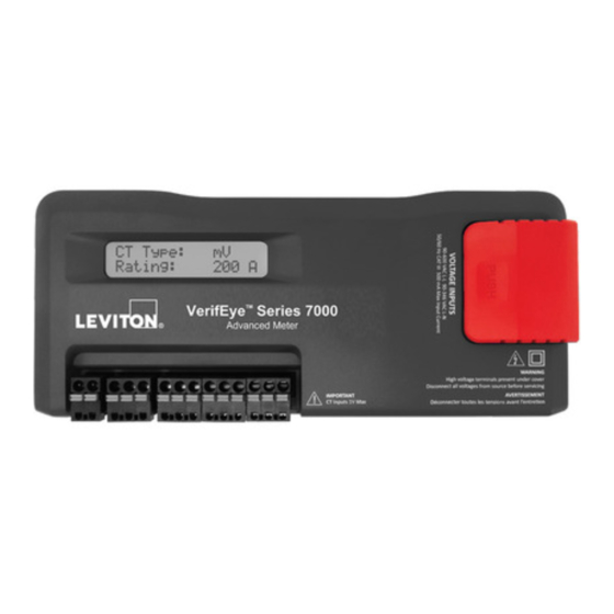
®
VerifEye
WARNINGS
• HAZARD OF ELECTROCUTION, SHOCK, EXPLOSION, OR ARC FLASH. CAREFULLY READ AND
FOLLOW INSTRUCTIONS:
• TO AVOID FIRE, SHOCK OR DEATH, turn OFF all power supplying equipment before working on or inside the equipment.
Use a properly rated voltage sensing device to confirm power is OFF.
• Follow safe electrical work practices. See NFPA 70E in the USA, or applicable local codes.
• This equipment MUST be installed and serviced by an electrician or other qualified personnel with the requisite knowledge,
training and experience related to the installation and operation of this equipment.
• Product may use multiple voltage/power sources. Be sure all sources of power have been disconnected before servicing.
• Do not depend on this product for voltage indication.
• Only install this product on insulated conductors.
• If the meter appears damaged or defective, first disconnect all power to the meter, and then call or e-mail Technical Support
for assistance.
DO NOT EXCEED 346V Line to Neutral or 600V Line to Line (L-L). This meter is equipped to monitor loads up to 346V Line to Neutral (L-N). Exceeding this voltage will cause damage to the meter and danger
to the user. Always use a Potential Transformer (PT) for voltages in excess of 346V L-N or 600V L-L. VerifEye-branded meters are 600 Volt Over Voltage Category III devices.
For use in a Pollution Degree 2 or better environment only. A Pollution Degree 2 environment must control conductive pollution and the possibility of condensation or high humidity. Consider the enclosure, the
correct use of ventilation, thermal properties of the equipment, and the relationship with the environment. Installation category: CAT II or CAT III.
Provide a disconnect device to disconnect the meter from the supply source. Place this device in close proximity to the equipment, and within easy reach of the operator, and mark it as the disconnecting
device. The disconnecting device shall meet the relevant requirements of IEC 60947-1 and IEC 60947-3 and shall be suitable for the application. In the US and Canada, disconnecting fuse holders can be used.
Provide over-current protection and disconnecting device for supply conductors with approved current limiting devices suitable for protecting the wiring. If the equipment is used in a manner not specified by the
manufacturer, the protection provided by the device may be impaired.
For the complete safety information for this product, see the full user guide at www.leviton.com.
DIN Rail Mount
1.
Attach DIN rail.
Attach a section of T35 DIN rail within a suitable
UL-approved enclosure.
NOTE:
• Leave enough clearance for voltage, CT, and
communications wires to route within enclosure.
• The customer must supply the UL-approved enclosure.
35mm
T35 DIN Rail
4.
Connect voltage leads.
WARNING: RISK OF ELECTRIC SHOCK, EXPLOSION, OR
ARC FLASH. DO NOT ENERGIZE METER WITH VOLTAGE
COVER REMOVED. FOLLOW ALL STATE AND FEDERAL
ELECTRICAL CODES.
USE #14 AWG THHN, 600V AC rated wire to connect the
voltage leads (L1, L2, L3 and N, as needed) to the meter
through a dedicated disconnect or circuit breaker.
NOTES:
• Do not exceed 346V L-N or 600V L-L.
• The meter is powered through the voltage between L1 and
L2. For single-phase installations in which no L2 exists, install
a jumper from N to L2. This connection provides power to the
meter, maintaining L1-N as the metering voltage reference.
Wall Mount
1.
Remove covers.
Wiring
WARNINGS:
• TO AVOID FIRE, SHOCK, OR DEATH; TURN OFF POWER at circuit breaker or
fuse and test that power is OFF before wiring!
• HIGH-VOLTAGE MAY BE PRESENT. To be installed by an electrician or other
qualified personnel only.
Configurations shown, are for service types available in the
METER SETUP drop-down menu.
4-WIRE, 3-PHASE WYE
RS-485
SHIELD
+
+
-
-
CURRENT
N
L3
L2
LOAD
L1
3-WIRE, 3-PHASE DELTA
RS-485
SHIELD
+
+
-
-
CURRENT
L3
LOAD
L2
L1
TYPICAL LOADS:
Single-phase L1-N or L2-N 110V AC: lighting, appliance, or living zone
Single-phase L1-L2 220V AC: water heater or equipment with no neutral wire
Split-phase L1-L2 220V AC: service entrance, dryers, or equipment with neutral wire
Single-Circuit Power Meter
FOR QUALIFIED PERSONNEL ONLY
INSTALLATION INSTRUCTIONS
2.
Mount.
• Press the top-edge of the meter's DIN rail channel into the DIN rail.
• Push the meter firmly towards the DIN rail until it clicks into place.
DIN Rail Channel
T35 DIN Rail
5.
Attach high-voltage cover.
Meter is IP30 TouchS
N
L1
L2
L3
2.
Mount.
Use the enclosure as a template.
L3
L2
L1
N
L3
NEUTRAL
L2
L1
VOLTAGE
L3
L2
L1
N
L3
L2
L1
VOLTAGE
Quick Start Guide
Cat. No. 70D03, 71D03
CAUTIONS
• This product is not intended for life or safety applications.
• Do not install this product in hazardous or classified locations.
• The installer is responsible for compliance with all applicable codes.
• Mount this product inside a suitable fire-proof and electrical enclosure.
• If the collector is connected directly to a source of voltage, the pulse isolator
DIN Rail Tabs
Pull tabs with screwdriver to release.
TM
(with internal cover installed).
3.
Follow steps 3 to 6 above to
complete the installation.
Wiring in a 3-Wire, Split-Phase Service Panel
3-wire, single-phase used
on MAINS L1-N, L2-N
(R Coil CTs shown)
Single-phase
110V AC plug loads
L1-N or L2-N
(Split Core CTs shown)
Wiring in a 4-Wire, 3-Phase Service Panel
4-wire, 3-phase
Mains Monitoring
L1-N, L2-N, L3-N
(R Coil CTs shown)
Single-phase
branch load
L1-N
4-wire, 3-phase
WYE load with
Neutral current
L1-N, L2-N, L3-N
immediately burns out and becomes non-responsive.
3.
Remove the high-voltage cover.
WARNING: RISK OF ELECTRICAL SHOCK. DO NOT
ENERGIZE METER WHEN VOLTAGE COVER IS REMOVED.
6.
Connect CT and
communications wiring.
Use only 333.3 mV (1/3 V) output CTs or R Coils.
CT Connections (x3)
RS-485
Bare (RŌC) (S)
Black or Brown (-)
White (+)
Example 1
Connect the NEUTRAL
wire to V INPUT 1 (N)
on the meter
N
Meter is powered
from L1 to L2 on
L1
L2
the V input 1 terminal
(label as disconnect)
Single-phase
220V AC plug load
3-wire, single-phase
L1-N, L2-N
Example 2
Connect the
Neutral wire
or Ground wire
to V INPUT 1 (N)
on the meter
Meter power
connect all phases
to V INPUT 1
(label as disconnect)
3-wire, 3-phase
Delta load
(no possibility of
neutral current)
Two CTs on L1 and L3
PK-A3464-10-00-0A
ENGLISH
High-
Voltage
Cover
USB-C Ethernet
L1-L2
split load
terminal
Advertisement

Related Manuals for Leviton VerifEye 70D03


Summary of Contents for Leviton VerifEye 70D03
- Page 1 Provide over-current protection and disconnecting device for supply conductors with approved current limiting devices suitable for protecting the wiring. If the equipment is used in a manner not specified by the manufacturer, the protection provided by the device may be impaired. For the complete safety information for this product, see the full user guide at www.leviton.com. PK-A3464-10-00-0A...
- Page 2 LIMITED 5 YEAR WARRANTY AND EXCLUSIONS Leviton warrants to the original consumer purchaser and not for the benefit of anyone else that this product at the time of its sale by Leviton is free of defects in materials and workmanship under normal and proper use for five years from the purchase date.
Need help?
Do you have a question about the VerifEye 70D03 and is the answer not in the manual?
Questions and answers
Can I collect data from this unit?
Yes, the Leviton 70D03 unit can collect data. It logs data in a Comma Separated Values (CSV) file, which includes energy readings and uses a 32-bit sequence counter for chronological tracking.
This answer is automatically generated