Table of Contents
Advertisement
Installation Guide
Power Monitoring
RoHS
Compliant
E50C2A
DANGER
HAZARD OF ELECTRIC SHOCK, EXPLOSION, OR ARC FLASH
• Turn off all power supplying equipment before working on or inside the equipment.
• Follow safe electrical work practices. See NFPA 70E in the USA, or applicable local codes.
• This equipment must only be installed and serviced by qualified electrical personnel.
• Read, understand and follow the instructions before installing this product.
• Product may use multiple voltage/power sources. Be sure all sources of power
have been disconnected before servicing.
• Use a properly rated voltage sensing device to confirm power is off.
DO NOT DEPEND ON THIS PRODUCT FOR VOLTAGE INDICATION
• Only install this product on insulated conductors.
Failure to follow these instructions will result in death or serious injury.
A quali ed person is one who has skills and knowledge related to the construction and
operation of this electrical equipment and the installation, and has received safety
training to recognize and avoid the hazards involved.
No responsibility is assumed by Leviton for any consequences arising out of the use of
this material.
Control system design must consider the potential failure modes of control paths and, for
certain critical control functions, provide a means to acheive a safe state during and after a
path failure. Examples of critical control functions are emergency stop and over-travel stop.
WARNING
LOSS OF CONTROL
Assure that the system will reach a safe state during and after a control path failure.
Separate or redundant control paths must be provided for critical control functions.
Test the e ect of transmission delays or failures of communication links.
Each implementation of equipment using communication links must be individually
and thoroughly tested for proper operation before placing it in service.
Failure to follow these instructions may cause injury, death or equipment damage.
For additional information about anticipated transmission delays or failures of the link, refer to
1
NEMA ICS 1.1 (latest edition). Safety Guidelins for the Application, Installation, and Maintenance
of Solid-State Control or its equivalent in your speci c country, language, and/or location.
CAUTION
• This product is not intended for life or safety applications.
• Do not install this product in hazardous or classified locations.
• The installer is responsible for conformance to all applicable codes.
• Mount this product inside a suitable fire and electrical enclosure.
FCC PART 15 INFORMATION
NOTE: This equipment has been tested by the manufacturer and found to
comply with the limits for a class B digital device, pursuant to part 15 of
the FCC Rules. These limits are designed to provide reasonable protection
against harmful interference when the equipment is operated in a
residential environment. This equipment generates, uses, and can radiate
radio frequency energy and, if not installed and used in accordance with
the instruction manual, may cause harmful interference to radio
communications. This device complies with part 15 of the FCC Rules.
Operation is subject to the following two conditions:
(1) This device may not cause harmful interference, and
(2) this device must accept any interference received, including
interference that may cause undesired operation.
Modifications to this product without the express authorization of the
manufacturer nullify this statement.
For use in a Pollution Degree 2 or better environment only. A Pollution Degree 2 environment
must control conductive pollution and the possibility of condensation or high humidity.
Consider the enclosure, the correct use of ventilation, thermal properties of the equipment,
and the relationship with the environment. Installation category: CAT II or CAT III. Provide
a disconnect device to disconnect the meter from the supply source. Place this device in
close proximity to the equipment and within easy reach of the operator, and mark it as the
disconnecting device. The disconnecting device shall meet the relevant requirements of IEC
60947-1 and IEC 60947-3 and shall be suitable for the application. In the US and Canada,
disconnecting fuse holders can be used. Provide overcurrent protection and disconecting
device for supply conductors with approved current limiting devices suitable for protecting
the wiring. If the equipment is used in a manner not specified by the manufacturer, the
protection provided by the device may be impaired.
ZL0139-0A
Page 1 of 24
1.800.561.8187
Compact Modbus Power and Energy Meter
For Use Only With U018 Series Rope CTs
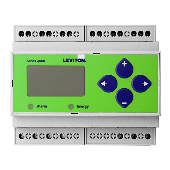
Product Overview
The Series 4000-R DIN rail meter provides a solution for measuring energy data with a single device. Inputs include
control power, CT, and 3-phase voltage. The Series 4000-R supports multiple output options, including solid state
U018 Series
relay contacts, Modbus, and pulse. The LCD screen on the faceplate allows instant output viewing. Series 4000-R
(sold separately)
meters include built-in CT integrators and CT power supplies. They work only with U018 Series rope style CTs.
The meter is housed in a plastic enclosure suitable for installation on T35 DIN rail according to EN50022. The Series
4000-R can be mounted with any orientation over the entire ambient temperature range, either on a DIN rail or in a
panel. The meter is not sensitive to CT orientation to reduce installation errors.
Product Identification
Series 4000-R
Unidirectional metering, Modbus full data set, pulse and alarm outputs. For use only with U018
rope style CTs.
Specifications
NEC2011 Article 100
Real Power and Energy
Reactive Power and Energy
1
Type of Measurement
Measured AC Voltage
Metering Over-Range
Measurement Input Range
www.
Series 4000-R
MEASUREMENT ACCURACY
IEC 62053-22 Class 0.5S, ANSI C12.20 0.5%
IEC 62053-23 Class 2, 2%
Current
0.4% (+0.015% per °C deviation from 25°C) from 5% to 100% of
range; 0.8% (+0.015% per °C deviation from 25°C) from 1% to 5% of
range
Voltage
0.4% (+0.015% per °C deviation from 25°C) from 90V
Sample Rate
2520 samples per second
Data Update Rate
1 sec
True RMS up to the 21st harmonic 60 Hz; One to three phase AC
system
INPUT VOLTAGE CHARACTERISTICS
Minimum 90V
L-N
UL Maximums: 600V
CE Maximum: 300V
+20%
Impedance
2.5 MΩ
/5 MΩ
L-N
Frequency Range
45 to 65 Hz
INPUT CURRENT CHARACTERISTICS
CT Scaling
20A to 5000A
U018 series rope style CTs only (CTs must be rated for connection to
Class 1 voltage inputs)
.com
(156V
) for stated accuracy;
L-L
(347V
)
L-L
L-N
L-N
L-L
information@itm.com
to 600VAC
L-N
L-L
05145
Advertisement
Table of Contents

Related Manuals for Leviton 4000-R Series


Summary of Contents for Leviton 4000-R Series
- Page 1 NEC2011 Article 100 No responsibility is assumed by Leviton for any consequences arising out of the use of this material. Control system design must consider the potential failure modes of control paths and, for...
- Page 2 Installation Guide Power Monitoring Series 4000-R CONTROL POWER 5VA max.; 90V min. UL Maximums: 600V (347 V CE Maximum: 300V 3 W max.; UL and CE: 125 to 300VDC Ride Through Time 100 msec at 120VAC OUTPUT Alarm Contacts N.C., static output (30VAC/DC, 100mA max. @ 25°C, derate 0.56mA per °C above 25°C) Real Energy Pulse Contacts N.O., static output (30VAC/DC, 100mA max.
-
Page 3: Table Of Contents
Installation Guide Power Monitoring Series 4000-R Table of Contents Dimensions Data Outputs Product Diagram Display Screen Diagram Installation Supported System Types Wiring Symbols Wiring Control Power Quick Setup Instructions Solid State Output User Interface Menu Abbreviations Defined User Interface for Data Configuration Alert/Reset Information User Interface for Setup RS-485 Communications... - Page 4 Installation Guide Power Monitoring Series 4000-R Dimensions 1.8” (45mm) 1.9” (48mm) 2.3” (59mm) 1.5” (39mm) 3.6” 4.2” (91mm) (107mm) Bottom View (DIN Mount Option) Bottom View (Screw Mount Option) 2.4 “ 4.2 “ (61 mm) (107 mm) 1.2 “ (31 mm) 0.3 “...
-
Page 5: Product Diagram
Installation Guide Power Monitoring Series 4000-R Product Diagram X2 X1 X2 X1 X2 X1 Alarm Energy OUTPUT (X2) (X1) (X2) (X1) (X2) (X1) + - S CT Inputs U018 Series Only Two 5-character rows of display text. Top row alphanumeric; ... -
Page 6: Installation
Installation Guide Power Monitoring Series 4000-R WARNING: TO AVOID FIRE, SHOCK, OR DEATH, disconnect power prior to installation. Installation Reinstall any covers that are displaced during the installation before powering the unit. Mount the meter in an appropriate electrical enclosure near equipment to be monitored. Do not install on the load side of a Variable Frequency Drive (VFD), aka Variable Speed Drive (VSD) or Adjustable Frequency Drive (AFD). -
Page 7: Supported System Types
Installation Guide Power Monitoring Series 4000-R Supported System The meter has a number of different possible system wiring configurations (see Wiring section). To configure the meter, set the System Type via the User Interface or Modbus register 130. The System Type tells the meter which of its current and voltage Types inputs are valid, which are to be ignored, and if neutral is connected. -
Page 8: Wiring
Installation Guide Power Monitoring Series 4000-R Wiring WARNING RISK OF ELECTRIC SHOCK OR PERMANENT EQUIPMENT DAMAGE CT negative terminals are referenced to the meter’s neutral and may be at elevated voltages · Do not contact meter terminals while the unit is connected ·... -
Page 9: Control Power
Installation Guide Power Monitoring Series 4000-R Wiring (cont.) Diagram 5: 3-Phase 4-Wire Wye Direct Voltage Input Diagram 6: 3-Phase 4-Wire Wye Connection 3 CT Connection 3 CT 3 PT Use System Type 40 (3L + 1n) Use System Type 40 (3L + 1n) L2 L3 L2 L3 White... -
Page 10: Quick Setup Instructions
Installation Guide Power Monitoring Series 4000-R Quick Setup These instructions assume the meter is set to factory defaults. If it has been previously configured, all optional values should be checked. Instructions – 1. Press the button repeatedly until SETUP screen appears. to the PASWD screen. -
Page 11: Solid State Output
Installation Guide Power Monitoring Series 4000-R Solid State Output The Series 4000-R meters have one normally open (N.O.) KY Form A output and one normally closed (N.C.) output.* One is dedicated to energy (Wh), and the other to Alarm. See the Setup section for configuration information. Over-Current Protective Device* (not supplied) ≤... -
Page 12: User Interface For Data Configuration
Installation Guide Power Monitoring Series 4000-R User Interface for Data Configuration ZL0139-0A Page 12 of 24 05145 1.800.561.8187 information@itm.com www. .com... -
Page 13: Alert/Reset Information
Installation Guide Power Monitoring Series 4000-R Alert/Reset Information To: ENRGY Alert Status PLOSS LOWPF F ERR I OVR V OVR PULSE (check if ALERT -------- -------- -------- -------- -------- -------- Wrench on A b C A b C A b C A b C Error LCD) - Page 14 Installation Guide Power Monitoring Series 4000-R UI for Setup To Setup p. 2 “SPASS” RS-485 Output BAUD -------- Set Communications Parameters: 38400 ADDR - Modbus Address: 1 – 247. ADDR -------- 19200 + increments the selected (blinking) digit. Back S COM -------- nOnE 9600...
- Page 15 Installation Guide Power Monitoring Series 4000-R UI for Setup (cont.) To Setup p. 1 “S PWR” Set Phase Loss: VOLTS - Phase Loss Voltage: The fraction of the system voltage below which Phase Loss Alarm is on. For system types with neutral, the Line to Neutral voltage is also calculated and tested.
- Page 16 Installation Guide Power Monitoring Series 4000-R RS-485 Daisy-chaining Devices to the Power Meter The RS-485 slave port allows the power meter to be connected in a daisy chain with up to 63 2-wire devices. Communications 120 Ω terminator on the first and last device of the daisy chain –...
-
Page 17: Standard Modbus Default Settings
Installation Guide Power Monitoring Series 4000-R Standard Modbus Setting Value Modbus Register Default Settings Setup Password 00000 – Reset Password 00000 – System Type 40 (3 + N) Wye CT Primary Ratio (if CTs are not included) 100A CT Secondary Ratio PT Ratio 1:1 (none) System Voltage... -
Page 18: Modbus Point Map Overview
= 0xFF if the operating system is used; status = 0x00 if the reset system is used bytes5+: ID string = “Leviton Series 4000R Power Meter Full Data Set” - RESET SYSTEM RUNNING RS Version x.xxx” last 2 bytes: CRC Read Device Identification, BASIC implementation (0x00, 0x01 and 0x02 data), Conformity Level 1. - Page 19 Installation Guide Power Monitoring Series 4000-R Modbus Point Map S4000-R R/W NV Format Units Scale Range Description Register 0-0xFFFF Real Energy Consumption (MSR) ULong Clear via reset register 0-0xFFFF Real Energy Consumption (LSR) UInt 0-32767 Total Instantaneous Real Power (3 Phase Total) UInt kVAR 0-32767...
- Page 20 Installation Guide Power Monitoring Series 4000-R Modbus Point Map (cont.) S4000-R R/W NV Format Units Scale Range Description Register MSR Contact Closure Counters. Valid for both Pulse ULong 0-0xFFFF Pulse Counter 1 (Real Energy) inputs and outputs. Series 4000 counts are shown in ().
- Page 21 Installation Guide Power Monitoring Series 4000-R Modbus Point Map (cont.) S4000-R R/W NV Format Units Scale Range Description Register -4 0.0001 SInt Scale Factor I (Current) Scale Factors -3 0.001 SInt Scale Factor V (Voltage) -2 0.01 Note: These registers contain a signed integer, SInt -1 0.1 Scale Factor W (Power)
- Page 22 Installation Guide Power Monitoring Series 4000-R Modbus Point Map (cont.) S4000-R R/W NV Format Units Scale Range Description Register Diagnostic Alert Bitmap. 1 = Active: Bit 0: Phase A Voltage out of range Bit 1: Phase B Voltage out of range Bit 2: Phase C Voltage out of range Bit 3: Phase A Current out of range Bit 4: Phase B Current out of range...
- Page 23 Installation Guide Power Monitoring Series 4000-R Modbus Point Map (cont.) S4000-R R/W NV Format Units Scale Range Description Register 277/278 R Float Real Power, Phase B 279/280 R Float Real Power, Phase C 281/282 R Float Ratio 0.0-1.0 Power Factor, Phase A 283/284 R Float Ratio...
-
Page 24: Troubleshooting
Installation Guide Power Monitoring Series 4000-R Troubleshooting Problem Cause Solution The maintenance wrench icon appears There is a problem with the inputs See the Alert sub-menu or the Diagnostic Alert Modbus in the power meter display. to the power meter. Register 146 The meter is not receiving adequate Verify that the meter control power are receiving the required...
Need help?
Do you have a question about the 4000-R Series and is the answer not in the manual?
Questions and answers