
Related Manuals for LINET Tom 2


Summary of Contents for LINET Tom 2
- Page 1 Instructions for Use and Technical Description Tom 2 Paediatric hospital bed D9U001K40-0101 Version: 13 Publication Date: 2020-08...
- Page 2 D9U001K40-0101 Version: 13 Publication Date: 2020-08 Copyright © LINET, s.r.o., 2020 Translation © LINET, 2020 All rights reserved. All trademarks and brands are the property of the appropriate owners. The manufacturer reserves the right to changes in the contents of this manual that relate to the product´s technical regulations. It is for this reason that the contents of this manual may indicate differences from the current manufacture of the product.
-
Page 3: Table Of Contents
1.10.3 Lock LED (Mini ACP) ..........14 14 Mattress ..............51 1.11 Night Bed Lighting (Tom 2 with PB43 control unit) ..14 14.1 EffectaCare 20P and CliniCare 10P ......51 1.12 Night Bed Lighting (Tom 2 with PB11 control unit) ..14 14.2 Rotating of the mattress ..........51... -
Page 4: Symbols And Definitions
1 Symbols and Definitions 1.1 Warning Notices 1.1.1 Types of Warning Notices Warning notices are differentiated by the type of danger using the following key words: ► CAUTION warns about the risk of material damage. ► WARNING warns about the risk of physical injury. ► DANGER warns about the risk of fatal injury. 1.1.2 Structure of Warning Notices SIGNAL WORDS! Type and source of danger! ►... -
Page 5: Symbols On The Package
1.4 Symbols on the Package FRAGILE, HANDLE WITH CARE THIS WAY UP KEEP DRY (PROTECT FROM HUMIDITY) PAPER RECYCLING SYMBOL DO NOT USE HAND TRUCK HERE DO NOT STACK DURING STORAGE D9U001K40-0101_13... -
Page 6: Symbols And Labels On The Bed
1.5 Symbols and Labels on the Bed READ INSTRUCTIONS FOR USE WARNING THERMAL PROTECTION OF TRANSFORMER ONLY SUITABLE FOR INDOOR USE PROTECTION AGAINST ACCIDENTS DUE TO ELECTRICAL CURRENT – TYPE B APPLIED PARTS SAFETY ISOLATING TRANSFORMER, GENERAL CE MARK OF CONFORMITY WITH EU REGULATION JACK FOR ATTACHMENT OF CONDUCTOR FOR POTENTIAL EQUALISATION SAFE WORKING LOAD MAXIMUM WEIGHT OF PATIENT... - Page 7 MANUFACTURER MANUFACTURING DATE REFERENCE NUMBER (PRODUCT TYPE DEPENDING ON CONFIGURATION) SERIAL NUMBER GO BUTTON (PRESS TO ACTIVATE CONTROL ELEMENT) STOP BUTTON (PRESS TO INTERRUPT BED POSITIONING) WEEE SYMBOL (RECYCLE AS ELECTRONIC WASTE, DO NOT PUT INTO THE HOUSEHOLD WASTE) RECYCLING SYMBOL DO NOT POLLUTE THE ENVIRONMENT MEDICAL DEVICE (COMPATIBLE WITH MEDICAL DEVICE REGULATION) D9U001K40-0101_13...
- Page 8 USE MATTRESS RECOMMENDED BY MANUFACTURER (WITH COMPATIBLE DIMEN- SIONS) DESCRIPTION OF ALLOWED LENGTH OF PATIENT UNIQUE DEVICE IDENTIFICATION (FOR MEDICAL DEVICES) MEDICAL BED FOR POSITIONING PATIENT IN MEDICAL BED MASS OF MOBILE HOSPITAL BED (MASS OF EMPTY BED + SAFE WORKING LOAD) D9U001K40-0101_13...
-
Page 9: Symbols And Labels On The Mattress
1.6 Symbols and Labels on the Mattress READ INSTRUCTIONS FOR USE CE MARKING COVER MATERIALS ARE FIRE RESISTANT TO BS7175, SOURCE 0, 1 AND 5 DO NOT IRON DO NOT USE PHENOL DO NOT WRING REGULARLY INSPECT THE INSIDE OF THE COVER FOR CONTAMINATION MACHINE WASH AT MAX. - Page 10 DISINFECT USING SOLUTION CONTAINING LESS THAN 1000 ppm OF CHLORINE (REFER TO INSTRUCTIONS FOR USE) RINSE WITH WATER TUMBLE DRY ON LOW HEAT SETTING (MAX. 60°C) MATTRESS FOOT PART HANDWASH WITH DETERGENT (INITIAL TEMPERATURE OF HOT WATER SHOULD NOT EXCEED 50°C) D9U001K40-0101_13...
-
Page 11: Serial Label
1.7 Serial Label Pictures of serial labels below serve just for explanation of the signs and fields on the serial labels. 1.7.1 Serial Label with UDI (Tom 2) 1K4XXXX-YY (Tom 2) Fig. Serial Label with UDI (Tom 2) Address of Manufacturer... -
Page 12: Serial Label (Mattress)
1.7.2 Serial Label (mattress) EffectaCare 20 P CliniCare 10 P 4PCLI1100AS 4PRKI1100AS 137x70x10 cm 137x70x10 cm Fig. Serial label (mattress Fig. Serial label (mattress - EffectaCare 20 P) - CliniCare 10 P) 1.7.3 Wash Label (mattress) Fig. Wash label (mattress) D9U001K40-0101_13... -
Page 13: Acoustic Signalisation (Tom 2 With Pb43 Control Unit)
Brake Signal (only version with Brake Signal) 1.9 Acoustic signalisation (Tom 2 with PB11 control unit) There are no acoustic signals in the case of Tom 2 bed with PB11 control unit. 1.10 Visual signalisation 1.10.1 Mains Power LED (Mini ACP) -
Page 14: Lock Led (Mini Acp)
1.11 Night Bed Lighting (Tom 2 with PB43 control unit) Tom 2 is equipped with undercarriage lighting. The lighting helps the patient or hospital personnel to better orientate in room with lowered or turned off light. The lowered intensity of lighting is set up after turning the bed on. -
Page 15: Definitions
1.13 Definitions Basic Bed Configuration the pricelist model configuration, not including a mattress Bed Weight The value depends on the product configuration, accessories or customer adjustments. Clearance of Undercarriage the height from the floor to the lowest point of the undercarriage between the castors, for the manipulation of accessories under a braked bed in the standard position Duty Cycle... -
Page 16: Abbreviations
1.14 Abbreviations AC ( ~ ) Alternating Current Attendant Control Panel European Conformity Cardiopulmonary Resuscitation Sound Intensity Unit DC ( Direct Current Configuration number Electromagnetic Compatibility Field-effect transistor High Frequency High Pressure Laminate Hardware Intensive Care Unit INT. Duty Cycle Ingress Protection Intravenous Light Emitting Diodes... -
Page 17: Safety Instructions
WARNING! Inappropriate handling of the power supply cord, e. g. by kinking, shearing or other mechanical damages is hazardous! WARNING! When routing cables from other equipment in the Tom 2 bed avoid squeezing those between parts of the Tom 2 bed! WARNING! Tom 2 bed should not be used with bed hoists and bed lifts! WARNING! To avoid risk of electric shock, this equipment must only be connected to a supply mains with protective earth. - Page 18 WARNING! The Tom 2 medical bed is intended for children! WARNING! Equipments in close proximity or attached to the Tom 2 medical bed can cause a hazard, e.g. entrapment or tipping over. WARNING! The Tom 2 medical bed shall not be used for transportation of a patient in any kind of vehicle.
-
Page 19: Safety Instructions
2.1 Safety instructions ► It is necessary to read the instructions for use before operating the bed. ► Follow the instructions carefully. ► Use the bed exclusively in its original condition. ► If necessary, check the bed functions daily or at each staff rotation. ►... -
Page 20: Intended Use (Tom 2)
50637 Design of the Tom 2 medical bed allows immediate and unimpeded access to the patient from the head end of the medical bed in emergency situations in application environments 1, 2 and 3. For application environments 1 and 2 the Tom 2 must be configured with removable head board and foot board. -
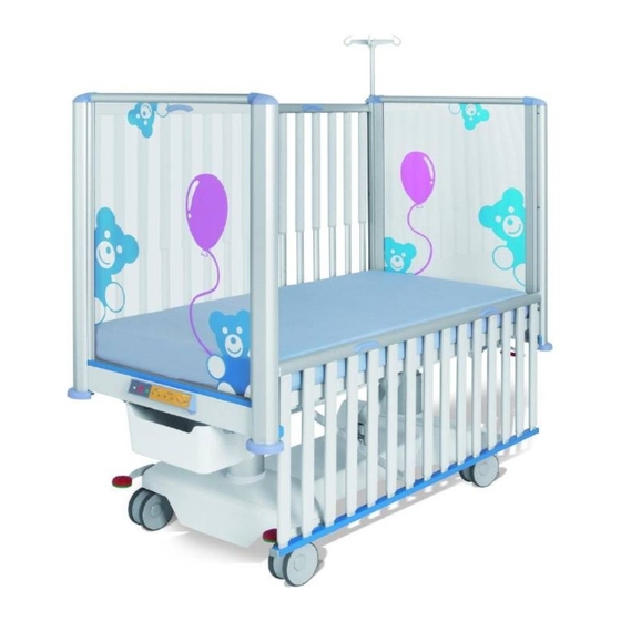
Page 21: Product Description
5 Product Description 5.1 Tom 2 (1K4) – Telescopic siderails with fixed head board and foot board Fig. Overview Tom 2 with fixed head board and foot board Foot Board Telescopic siderail Siderail release mechanism Head Board Protective bumper 6. CPR control lever – backrest release (optional) Undercarriage cover Mattress support platform Holder for extension system or accessories Castor 11. ... -
Page 22: Tom 2 (1K4) - Telescopic Siderails With Removable Head Board And Foot Board
5.2 Tom 2 (1K4) – Telescopic siderails with removable head board and foot board Fig. Overview Tom 2 with removable head board and foot board Removable Foot Board Telescopic siderail Siderail release mechanism Removable Head Board Protective bumper 6. CPR control lever – backrest release (optional) -
Page 23: Technical Specification
6 Technical Specification All technical data are rated data and are subject to construction and manufacturing tolerances. 6.1 Type B Applied Parts All part of the bed (and accessories) the patient can reach are type B Applied Parts. List of type B applied parts: ■ ... -
Page 24: Environment Conditions
2x T1.6A L 250 V for 230 V version Version 2 2x T3.15A L 250 V for 100-127 V version NOTE Upon request, LINET® can deliver hospital beds with electrical specifications that comply with regional standards (custom voltage, different mains plugs). D9U001K40-0101_13... -
Page 25: Electromagnetic Compatibility
6.5 Electromagnetic compatibility Bed is intended for hospitals except for near active HF surgical equipment and the RF shielded room of a medical system for mag- netic resonance imaging, where the intensity of EM disturbances is high. Bed has defined no essential performance. WARNING! It is recommended to avoid the use of this device next to or in block with other device, because it could lead to ... -
Page 26: Manufacturer Instructions - Electromagnetic Emissions
6.5.1 Manufacturer instructions - electromagnetic emissions Emission Test Compliance RF emissions Group 1 CISPR 11 RF emissions Class B CISPR 11 Harmonic emissions Class A IEC 61000-3-2 Voltage fluctuations / flicker emissions Complies IEC 61000-3-3 6.5.2 Manufacturer instructions - electromagnetic susceptibility Immunity Tests Compliance level Electrostatic discharge (ESD) -
Page 27: Use And Storage Conditions
Table 1 - IMMUNITY to RF wireless communications equipment Test frequency (MHz) Band (MHz) Service Modulation Immunity Test Level 380 - 390 TETRA 400 Pulse modulation 18 Hz 430 - 470 GMRS 460, FRS 460 FM ± 5 kHz deviation 1 kHz sine 704 - 787 LTE band 13, 17... -
Page 28: Scope Of Delivery And Bed Variants
Notify the carrier and supplier of any deficiencies or damages immediately as well as in writing or make a note on the delivery note. 8.2 Bed Variants Features – Tom 2 Model 1K4 (for model no. see product label): ■... -
Page 29: Putting Into Service
9 Putting into Service WARNING! Risk of injury when working on the bed! ► Ensure that the bed is disconnected from the mains connection prior to putting into service, putting out of service and maintenance. ► Ensure that the castors are locked prior to putting into service, putting out of service and maintenance. CAUTION! Material damage due to incorrect putting into service! ►... -
Page 30: Accumulator Activation
9.1 Accumulator Activation 9.1.1 Placement of Control Section 9.1.2 Removing the Isolating Foil PULL 9.1.3 Isolating Foil Check if isolating foil is complete and undamaged as shown: If isolating foil is damaged, contact the manufacturer’s service department immediately. NOTE: It is recommended to wear gloves when removing the isolating foil. D9U001K40-0101_13... -
Page 31: Mattress Support Platform
Mini ACP is located at the foot end of the bed. LEFT SIDE RIGHT SIDE Fig. 2-part mattress support platform (Tom 2) 9.2.1 Auto-Regression To eliminate pressure on the pelvis of the patient as it is raised, the backrest moves in the opposite direction when the bed is adjus- ted. -
Page 32: Potential Equalisation
9.3 Potential Equalisation The bed is equipped with a standard protective connector. This connector is used for potential equalisation between the bed and any intravascular or intracardiac device connected to the patient to protect the patient from static electric shocks. Fig. -
Page 33: Head Board And Foot Board
Ensure nobody burdens siderails or head board/foot board. The bed Tom 2 can be equipped with removable head board and foot board or with non-removable head board and foot board. Removable head board and foot board allows easier access to the patient. - Page 34 To remove head board and foot board: ► Unlock both locks on the upper part of the head board or foot board by pushing in the direction of arrows (1). ► Grab the head board or foot board with both hands in the upper half of the head board or foot board. ►...
- Page 35 To insert head board and foot board: ► Insert the head board or foot board into the bed (1). ► Put the head board or foot board into the guides on top and bottom of the columns (2 & 3) on both sides. ►...
-
Page 36: Before Use
9.5 Before Use CAUTION! Material damage due to temperature difference! ► If there is a considerable temperature difference between the bed and the place of operation (after transport/storage), leave bed unconnected for 24 hours to allow the temperature to equalise. Prepare the bed for service as follows: ►... -
Page 37: Accumulator
11 Accumulator CAUTION! Risk of reducing accumulator durability due to incorrect use! ► Use bed on accumulator only in crisis situations (e.g.: power blackout, patient complications during transport, etc.). ► After reconnecting bed to the mains charge accumulator to full capacity (see chart Accumulator charge status). CAUTION! Risk of damage or destruction of accumulator! ►... -
Page 38: Status Faulty Accumulator
To maintain maximum functionality of the accumulator: ► Unplug the bed from the mains as least as possible. In case the accumulator cover or control section is deformated by heat ► Unplug the bed from the mains. ► Do not use the bed (see. Removing the Bed from Service. ►... -
Page 39: Manipulation
12 Manipulation WARNING! Risk of injury when adjusting the bed! ► Ensure there are no body parts between the mattress platform elements and the mattress platform frame when adjusting the bed. ► Ensure there are no body parts below the mattress platform frame before adjusting the bed. ►... -
Page 40: Central Stop Button
To set positions: ► Activate the keypad by pressing the GO button. ► Press and hold corresponding button until required position is reached. 12.1.1 Central STOP Button The central STOP button 2 immediately interrupts all bed movements. Pressing central STOP button 2 for at least 0.3 seconds immediately stops all electronic bed movements. NOTE: The bed can be stopped by pressing two different buttons even on two different controllers. - Page 41 LOCK To lock Backrest Adjustment: ► Press button ► Touch the place on the keyboard of Mini ACP (12) by the portable key. Lock LED 11 and Lock LED 10 are flashing slowly. ► Press button 4 or button 5. Lock LED 11 is flashing quickly. ►...
-
Page 42: Cpr Backrest Release (Optionally Available)
12.2 CPR Backrest Release (optionally available) WARNING! Risk of injury due to lowering the backrest too quickly! ► Ensure the telescopic siderails are in their lowest position! ► Ensure there are no body parts between siderails and backrest. The bed permits mechanical lowering of the backrest for emergency resuscitation (CPR) procedures. There are two CPR control levers located under the bed frame under the head board for this purpose. -
Page 43: Quick Lowering Of The Backrest
12.3 Quick lowering of the backrest WARNING! Risk of crushing and trapping during quick lowering of the backrest! ► Extra care must be taken to avoid pinching a hand or fingers between the backrest and the bed frame during quick lowering of the backrest! ► Hold the backrest with one hand during quick lowering of the backrest to prevent the other hand from being pinched or perform the quick lowering of the backrest with the help of a second person who will hold the backrest all the time during lowering of the backrest so that it does not fall down spontaneously! WARNING! Restriction of the backrest positioning after the quick lowering of the backrest ► It is necessary that hospital technician enables the backrest positioning again after the quick lowering of the backrest by connecting the backrest to the piston of actuator! ► If hospital personnel immediately need to position the backrest after the quick lowering of the backrest, the patient must be placed on another bed that allows this positioning! 12.3.1 Description of the connection of the backrest to the piston of actuator Backrest is connected to the piston of actuator by a removable catch. Removing this catch enables the quick lowering of the backrest. -
Page 44: Procedure Of The Quick Lowering Of The Backrest
12.3.2 Procedure of the quick lowering of the backrest In the emergency case, hospital personnel perform the quick lowering of the backrest from the side of the bed. Fold the siderail on the side of the bed down to the lowest position. 2) If the backrest is not high enough to place a hand under it, lift the backrest. 3) Hold the backrest with one hand so that it does not fall down. 4) Remove the catch connecting the backrest to the piston of actuator with the other hand. -
Page 45: Procedure To Reconnect The Backrest To The Piston Of Actuator
Fig. Releasing (4) and removing (5) the catch connecting the backrest to the piston of actuator 12.3.3 Procedure to reconnect the backrest to the piston of actuator Hospital technician performs the reconnection of the backrest to the piston of actuator from the side of the bed. It is recommended that two people reconnect the backrest to the piston of actuator, one holding the backrest and the other inserting and securing the catch. -
Page 46: Siderails
12.4 Siderails WARNING! The hospital personnel is responsible for locking the siderails in the highest position when the patient is on the bed or when the bed is transported. WARNING! Ensure that there are no objects or body parts between the bars of siderail when folding the siderail up or down. CAUTION! Material damage due to excess load! Ensure nobody burdens siderails or head board/foot board. The telescopic siderails are components of the bed. The siderails cannot be dismounted. Fig. - Page 47 Fig. Incorrectly locked siderail D9U001K40-0101_13...
-
Page 48: Positions Of Siderails
12.4.1 Positions of siderails It is possible to fix siderails in 5 positions. D9U001K40-0101_13... -
Page 49: Openable Siderail Bars (Optionally)
12.4.2 Openable siderail bars (optionally) WARNING! Risk of damaging due to incorrect use! ► Always ensure the openable bar is locked properly. Check the locking by pulling the bar up, down, to- wards and from you. ► Never leave the bed with opened bars without supervision of hospital personell if the patient is on the bed. ► Ensure that no accessories is blocked in locking mechanism or is blocking the locking mechanism. ► Do not position siderail if openable siderail bar is not locked in the lowest position! Openable siderail bars are equipped with safety brake reducing speed of their uncontrolled lowering. ► Safety brake of the siderail bars functions correctly if speed of the uncontrolled lowering to the down position takes more than 1 second. Contact service department of the manufacturer if the uncontrolled lowering to the ... -
Page 50: Castor Control And Bed Transport
Fig. Pressed locking pin 12.5 Castor Control and Bed Transport CAUTION! Material damage due to incorrect transport or involuntary movement! ► Prior to assembly, disassembly and maintenance, ensure the castors are locked. ► Ensure the castors are locked while the bed is occupied and/or not being transported. ►... -
Page 51: Equipment
14.1 EffectaCare 20P and CliniCare 10P Mattresses EffectaCare 20P and CliniCare 10P for Tom 2 are designed for child patients on the paediatric departments. EffectaCa- re 20 Paediatric has monoblock polyurethane foam. CliniCare 10 Paediatric is double layer mattress. It has bottom cold polyuretha- ne foam and top Geltex foam. -
Page 52: Technical Specification Of Compatible Mattress
Fig. Rotating of the mattress Rotating - This means replacing the head and foot end of the mattress. 14.3 Technical specifi cation of compatible mattress Parameters Eff ectaCare 20 P CliniCare 10 P External dimensions (length x 137 cm x 70 cm x 10 cm 137 cm x 70 cm x 10 cm width x height) (Foam) -
Page 53: Mattress Cleaning And Disinfectants
14.4 Mattress cleaning and disinfectants ► Mattress covers can be disinfected with most common disinfectants. ► If disinfecting is not required, cleaning with soap and water should be enough to remove dirt stains. ► Cleaning and disinfecting products based on solvent, bleach, abrasives or high alcohol concentrations can damage this product. -
Page 54: Routine Cleaning And Disinfection
14.4.2 Routine Cleaning and Disinfection Cleaning the mattress: ► Check mattress cover top for any signs of damage or for liquid ingress. ► Replace or repair and completely disinfect mattress cover top if damaged. Also check if the mattress core is not contaminated. -
Page 55: Accessories
Oxygen bottle holder ■ Pole for devices and accessories □ chrome-plated NOTE: It is possible to attach additional IV pole compatible with Tom 2 to the bed. 15.1 Infusion Stand (integrated) WARNING! Risk of injury due using of unsuitable accessories! ► Use infusion stands exclusively for accessories listed in the instructions for use. -
Page 56: Cleaning/Disinfection
16 Cleaning/Disinfection WARNING! Risk of injury when working on the bed! ► Prior to assembly, disassembly, cleaning and maintenance, ensure that all adjustment functions are locked. ► Ensure the bed is disconnected from the mains during cleaning process. ► Pay extra attention when cleaning any movable or controlling mechanisms of the bed to prevent involuntary activation, entrapping or crushing. -
Page 57: Safety Instructions For Cleaning And Disinfection Of The Bed
16.1 Safety Instructions for Cleaning and Disinfection of the Bed Preparation for cleaning: ► Drive the bed on a place where the cleaning process will be performed and then brake the bed. ► Position the mattress platform to its highest positions and also position the backrest and thighrest parts so the back side of those parts are accessible for cleaning. -
Page 58: Modes Of Cleaning And Disinfection
16.3 Modes of Cleaning and Disinfection Part of bed – Tom 2 Daily C&D Changing patient C&D Complete C&D Telescopic siderails ■ Telescopic bars ■ Releasing mechanism ■ Upper bar ■ Bottom bar ... -
Page 59: Troubleshooting
17 Troubleshooting DANGER! Danger to life due to electric shock! ► If a fault occurs ensure the electric motor, power box and other electrical parts checked by qualified personnel only. ► Do not open protective covers of the electric motor or power box. Error/Fault Cause Solution Adjusting with position buttons not GO button was not pressed Press the GO button. -
Page 60: Maintenance
Ensure that maintenance is performed exclusively by manufacturer´s customer service or by authorised service personnel certified by the manufacturer. ► If the defect cannot be repaired, do not use the bed. LINET ® recommends attaching the maintenance plaque to the bed. 18.1 Regular maintenance ► Check regularly movable parts for wear. -
Page 61: Disposal
Based on the Directive No. 2002/96/ EC (Directive WEEE - Waste, Electric and Electronic Equipments) the company LINET, s. r. o. is registered in the List of Electric and Electronic Equipment Producers (Seznam výrobců elektrozařízení) on the Ministry of the Environment of the Czech Republic... -
Page 62: Warranty
20 Warranty LINET ® will only be held responsible for the safety and reliability of products that are regularly serviced, maintained and used in accordance with the safety guidelines. Should a serious defect arise that cannot be repaired during maintenance: ►...
Need help?
Do you have a question about the Tom 2 and is the answer not in the manual?
Questions and answers