Table of Contents
Advertisement
Quick Links
Advertisement
Table of Contents

Related Manuals for Compliance West MegaPulse 1.2x50/8x20-2PF-HR


Summary of Contents for Compliance West MegaPulse 1.2x50/8x20-2PF-HR
- Page 1 Instruction Manual...
- Page 3 To fully appreciate all the features of your new instrument, we suggest that you take a few moments to review this manual. Compliance West USA stands by your instrument with a full one-year warranty. If the need arises, please don't hesitate to call on us.
-
Page 5: Table Of Contents
Using the MegaPulse Impulse Tester ................4 Section 2 ..............................5 Getting Started..........................5 Unpacking and Inspection ..................... 5 Product Package for MegaPulse 1.2x50/8x20-2PF-HR Tester ........5 Returning the Instrument ....................5 AC Line Voltage Requirements ..................5 Fuse Replacement ......................6 Section 3 .............................. -
Page 7: Section 1
Section 1 An Introduction to Impulse Testing with the MegaPulse PF series tester The impulse test is designed to simulate impulse surges which occur in everyday life due to nearby lightning strikes, switching transients, and other high-frequency faults on the power distribution network. Impulse testing is the fundamental method for empirical verification of the adequacy of insulation. -
Page 8: Safety Techniques
Safety Techniques The high voltage circuit of the MegaPulse 1.2x50/8x20-2PF-HR 2/12 ohm can be shut off at any time by turning OFF the rear power switch. Always press TRIGGER to discharge the tester before turning OFF. The MegaPulse tester is provided with a digital VOLTAGE ADJUST knob on the front panel. This voltage setting should always confirm by pressing the VOLTAGE ADJUST knob before starting any testing. -
Page 9: Using The Megapulse Impulse Tester
Using the MegaPulse Impulse Tester The impulse test involves high voltage and caution should be exercised when using the tester. The RETURN lead is referenced to building ground when properly connected. However, both the OUTPUT and RETURN leads must always be treated as Hazardous whenever the power switch of the MegaPulse is in the ON position. The MegaPulse impulse tester generates the impulse waveform only;... -
Page 10: Section 2
Mark the container as “FRAGILE” to insure proper handling. • Please contact Compliance West USA (1-800-748-6224) to inform about the service for your instrument. AC Line Voltage Requirements AC line voltage requirements for your Tester are noted on the rear panel of the instrument. Do not connect the instrument to a different voltage source. -
Page 11: Fuse Replacement
Fuse Replacement There is a user-replaceable fuse (F1) located on the rear panel of the instrument. It is located behind a door in the Power Inlet-Power Switch-Fuse Holder device. The fuse rating is noted on the rear panel. Do not attempt to replace it with a fuse of any other rating. -
Page 12: Section 3
Section 3 Specifications and Tolerances MegaPulse 1.2x50/8x20-2PF-HR complies with IEC 61000-4-5. Capable of generating up to 2000V and 1000A. The tester is designed with high-resolution charging steps of 0.2V in the range of 5-200V and 2V in the range of 201- 2000V. -
Page 13: Section 4
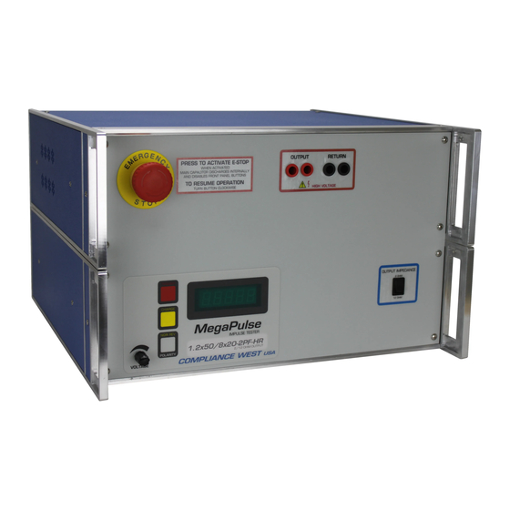
Section 4 Controls and Indicators Before using your Tester, take a few minutes to become familiar with the use of its controls, indicators and connectors on the front and rear panel. Front Panel Features The front panel features are shown in Figure 1 and are described in Table 2. Figure 1. -
Page 14: Rear Panel Features
This Red indicator is lit to show that the tester can be trigger. TRIGGER TRIGGER indicator is lit for 2 minutes after the CHARGE button is pressed. indicator TRIGGER indicator will go out after pressing TRIGGER button. TRIGGER and CHARGE Indicators will be blinking if the Interlock Switch is open. Displays the output voltage set point. -
Page 15: Section 5
When the Interlock is closed, it enables all normal operations of the MegaPulse features. Front Keyboard and Voltage Knob Enable If the MegaPulse 1.2x50/8x20-2PF-HR Tester has disabled the keyboard or Voltage Knob, it is possible to enable them by using the next keyboard sequence: Turn OFF the MegaPulse P tester. -
Page 16: Polarity Pulse Selection
Polarity Pulse Selection NOTE If the red Trigger light is lit or more than 200V remains on the internal capacitor, the polarity pulse selection will be automatically blocked for safety reasons. Turn the rear-panel Power Switch ON. Positive polarity always is set by default after the unit is turned ON. Press the POLARITY switch button to toggle between positive and negative. -
Page 17: Pulse Verification Procedure
Pulse Verification Procedure The following procedure will verify that the high voltage pulse is properly generated by the MegaPulse tester. We recommend that this procedure be conducted periodically to ensure proper operation of the tester. The following items are needed to conduct this procedure: •... -
Page 18: Section 6
THE OPERATING INSTRUCTIONS. Introduction This section of the manual contains maintenance information for the MegaPulse 1.2x50/8x20-2PF-HR impulse tester. A 1-year calibration cycle is recommended to maintain the specifications of the factory. The test equipment required for the performance test is a digital oscilloscope, high voltage oscilloscope probe, current monitor, digital meter and a high voltage probe. -
Page 19: Voltage Stop Disable / Keyboard Enable By Keyboard
Voltage Stop Disable / Keyboard Enable by Keyboard. If the MegaPulse 1.2x50/8x20-2PF-HR tester includes TestMinder option and has the Voltage Stop by the PC command activated, it is possible to disable it using the next keyboard sequence: Note: Disabling Voltage Stop enables the keyboard. -
Page 20: Section 7
Section 7 Technical Assistance Technical Assistance from Compliance West USA is available: Phone: (800) 748-6224 Hours: 8:00 AM - 4:00 PM Pacific Time. Also available on our web site at: www.compwest.com Contact: Compliance West USA 650 Gateway Center Way, Suite D San Diego, CA, 92102 United States of America.
Need help?
Do you have a question about the MegaPulse 1.2x50/8x20-2PF-HR and is the answer not in the manual?
Questions and answers