
Related Manuals for Compliance West HT-25KVP dc


Summary of Contents for Compliance West HT-25KVP dc
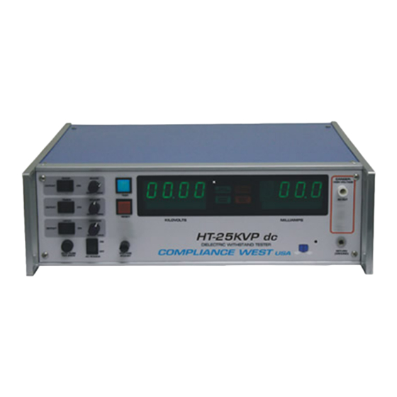
- Page 1 Dielectric Withstand Tester Model HT-25KVP dc 0 - 25,000 Volts DC Output Instruction Manual...
- Page 3 To fully appreciate all the features of your new meter, we suggest that you take a few moments to review this manual. Compliance West USA stands by your instrument with a full one- year warranty. If the need arises, please don't hesitate to call on Thank you for your trust and confidence.
-
Page 5: Table Of Contents
Table of Contents Quick Start ........................... 1 Initial Setup ........................1 An Introduction to Dielectric Withstand Testing with the HT-25KVP dc ......... 2 Leakage Test ........................2 High Voltage Dielectric Withstand Test ................ 2 High Voltage Discharge ....................3 Introduction and Specifications ....................4 Specifications ......................... -
Page 6: Quick Start
Section 1 Quick Start For a quick look at the abilities of the HT-25KVP dc, we are providing this quick start page, designed to get you up and running quickly. We recommend that you read the entire manual before using the HT-25KVP dc to conduct actual testing. -
Page 7: An Introduction To Dielectric Withstand Testing With The Ht-25Kvp Dc
Full Voltage indicator is lit to the completion of the test. The Timer Control Switch must be set to ON, or the HT-25KVP dc will test only while the Test Button is pressed. The minimum test time is one second regardless of the setting of the Timer... -
Page 8: High Voltage Discharge
High Voltage Discharge The HT-25KVP dc has an internal circuit designed to remove the high voltage, after completion of the dielectric withstand test. The HT-25KVP dc should remain connected to the circuit until the front panel meter shows that the output voltage has dropped to a safe level. -
Page 9: Introduction And Specifications
- Test results are determined quickly, without operator intervention. - The HT-25KVP dc allows custom setups for voltage ramp, test time and leakage limit. Your Tester has a warranty for a period of one year upon shipment of the instrument to the... -
Page 10: Specifications
Failure Indication Audible, provided by internal buzzer Visual, provided by red LEDs, on front panel Test can be automatically terminated on failure Leakage Test Provided; 5 mA DC factory set pass/fail point, user adjustable. Table 3-1. HT-25KVP dc Specifications... -
Page 11: Operation
Before using the HT-25KVP dc tester, take a few minutes to become familiar with the use of its controls, indicators, and connectors. The front panel features of the HT-25KVP dc are shown in Figure 4-1 and described in Table 4-2. - Page 12 Figure 4-1. Front Panel Controls, Indicators and Connectors...
- Page 13 ITEM NAME FUNCTION When ON, Dielectric breakdown detect will be activated. When in DEFEAT position, test will continue regardless of a dielectric breakdown, but it can be stopped by the excess HIPOT leakage limit. NOTE: The RAMP switch, and TIMER switch must also be in the DEFEAT position, otherwise the buzzer will sound.
-
Page 14: Initial Checkout Procedure
Initial Checkout Procedure Use this procedure to verify that the HT-25KVP dc tester is working correctly. Refer to table 4-1, figure 4-1 and table 4-2 for location of items. CAUTION High voltage, risk of shock, use with care. 1. Turn the Tester on using the AC Power switch. -
Page 15: Setting Up The Ht-25Kvp Dc For Laboratory Testing
2 seconds, and the meter will display “d” with the Test Duration set time in seconds. Leakage Current Level Adjust 1. Connect the HT-25KVP dc to a correctly rated source of supply and turn ON the tester. 2. Push the RESET button. The TEST indicator should light, indicating that the HT-25KVP dc is ready. -
Page 16: Voltage Adjust
9. Release the TEST button to terminate the test. High Voltage Test Time Adjust This procedure sets the length of time the HT-25KVP dc will conduct the high voltage test. The test time is specified by the safety agencies, and is tied to the test voltage. Most safety agencies will allow a much shorter test (usually 1 second vs. -
Page 17: Setting The Test Timer Switch
Shutdown Limit Defeat is desired. See Table 4-3 for details. Setting the Test Timer Switch The Timer Control switch allows test time to be controlled by the HT-25KVP dc internal timer or to continue until terminated by the operator. -
Page 18: Test Results
HT-25KVP dc. If the Timer Control switch is set to ON, the HT-25KVP dc will conduct the high voltage test for the amount of time set in the Test Duration procedure. - Page 19 Ramp Time: May be set too fast. A very fast ramp time may allow input capacitors to act as short circuits, triggering a Leakage Current Fail light and terminating the test. Consider to have a slower Ramp Time, by increasing the time; see Ramp Time Adjust.
- Page 20 Full voltage is produced at the output immediately. Test will continue only as long as the TEST button is held in, minimum one second. The HT-25KVP dc will NOT shut down on a dielectric failure, but the front panel Hipot Fail light will flash to indicate a dielectric breakdown. The Hipot Pass light will not light at the completion of a successful test.
-
Page 21: Maintenance And Calibration
Section Service Information The HT-25KVP dc is warranted to the original purchaser for a period of 1 year. This warranty does not cover problems due to misuse or neglect. Malfunctions which occur within the limits of the warranty will be corrected at no charge. -
Page 22: Entering Calibration Mode
ALL ADJUSTMENTS. Entering Calibration Mode NOTE Only enter into this mode if the HT-25KVP dc unit needs a re-calibration on any of the parameters of Voltage Meter or Leakage. Turn Off the HT-25KVPac unit. Hold in both the Test and Reset buttons. -
Page 23: Voltage Meter Verification
Press the Test button and turn up the Voltage Adjust to compare the front meter of the HT- 25KVP dc unit vs. the external volt meter, tolerance most be +/-0.2KV full scale. If one value is out of the specified tolerances, the HT-25KVP dc unit needs a voltage meter re-calibration. Follow the Voltage Meter Re-Calibration procedure. -
Page 24: Leakage Meter Verification
Reading on the external meter should be +/- 0.1mA full scale. If one value is out of the specified tolerances, the HT-25KVP dc unit needs a leakage current re-calibration. Follow the Leakage Current Re-Calibration procedure. - Page 25 (mA scale) equals the number showed on the front meter of the HT-25KVP dc unit, then, press the Test button and the front display will show “hold” for a few seconds, wait until the front display show again "L1" again.
-
Page 26: Technical Assistance
Section 6 Technical Assistance Technical Assistance from Compliance West USA is available: Phone: (800) 748-6224 Hours: 8:30 AM - 4:30 PM Pacific Time. Also available on our web site at: www.compwest.com Contact: Compliance West USA 650 Gateway Center Way, Suite D, San Diego, CA., 92102...
Need help?
Do you have a question about the HT-25KVP dc and is the answer not in the manual?
Questions and answers