
Related Manuals for Compliance West HT-S Series


Summary of Contents for Compliance West HT-S Series
- Page 1 HT-S Series Dielectric Withstand Tester With Ground Continuity Check Instruction Manual for Models HT-2000S (0-2000VAC) HT-2800S (0-2800VDC) HT-3000S (0-2000VAC/0-2800VDC) HT-4200S (0-3000VAC/0-4200VDC)
- Page 3 Dear Customer: Congratulations! Compliance West USA is proud to present you with your Dielectric Withstand Tester. Your instrument features a groundbreaking logic-controlled circuit design and ergonomic front panel, and represents the latest in high voltage production line testing. To fully appreciate all the features of your new meter, we suggest that you take a few moments to review this manual.
-
Page 4: Table Of Contents
Table of Contents Section 1 ............................6 Introduction and Safety ....................6 An Introduction to Dielectric Withstand Testing with the HT-S .....6 Safety Precautions ...................6 Test Personnel ....................7 Testing Area ....................7 Safety Techniques....................7 Safety Markings ....................8 Using the HT-S Dielectric Withstand Tester ..............9 Ground Continuity ...................9 Ground Continuity Failures ...............9 Defeating the Ground Continuity ............9... - Page 5 Technical Assistance ......................30 Contact Information ..................30 Section 5 ............................31 Maintenance and Calibration ..................31 Service Information ..................31 Cleaning ......................31 Calibration Information ...................31...
-
Page 6: Section 1
Section 1 Introduction and Safety An Introduction to Dielectric Withstand Testing with the HT-S The continuity test/dielectric withstand test is a production line test which is recognized by safety agencies worldwide as a valid criterion of safe assembly of end-use equipment. The test ensures that the primary circuit power and ground conductors were properly wired and connected for safe operation. -
Page 7: Test Personnel
Test Personnel Personnel require special training to conduct the dielectric withstand test. They should understand electrical fundamentals clearly, and be aware that high voltage is adept and creative at completing a path to ground. Instructions should include a warning against any metal jewelry. Operators should not allow others in the testing area, especially when tests are being conducted. -
Page 8: Safety Markings
The HT-S has been designed for one-touch operation with the right hand. If possible, it should be set up to the left and in front of the equipment under test. The equipment under test should be connected to the HT-S and then left alone by the operator. After the operator is clear of the Tester and the equipment under test, he should press the RESET Button, then the TEST button, with his right hand. -
Page 9: Using The Ht-S Dielectric Withstand Tester
Using the HT-S Dielectric Withstand Tester The dielectric withstand test involves high voltage and caution should be exercised when using the tester. The return lead of the tester is connected to ground potential and when properly connected to the equipment being tested, it will guard against the operator contacting high voltage. Always make sure the return lead is firmly connected to exposed dead metal before start testing. -
Page 10: Leakage Test
Leakage Test The HT-S leakage test uses a low-frequency circuit to check for excessive leakage between primary power components and ground. There is not a specific leakage current level pass/fail requirement at this time for most equipment, however, higher than normal leakage current on a particular part may indicate an assembly or component problem in the primary circuit. -
Page 11: High Voltage Dielectric Withstand Test
Various adapters and pigtail leads are available from Compliance West USA, or you can make your own, just make sure for the correct configuration see the description of the outputs in the connections section. If tests of this type are... -
Page 12: Section 2
Section 2 Specifications and Controls Introduction This manual contains complete operating, maintenance and calibration instructions for the models HT-2000S, HT-2800S, HT-3000S and HT-4200S Dielectric Withstand Testers, please see Table 1 for specifications. The instrument is a bench-type Dielectric Withstand Tester with AC and/or DC Output, designed for production line testing. - Page 13 0 - 2800 Volts DC HT-2800S, HT-3000S 0 - 3000 Volts AC HT-4200S 0 - 4200 Volts DC HT-4200S Pigtail and Receptacle adapters available for most configurations. Contact Compliance West for more information. Leakage Current 1 - 10mA AC HT-4200S 1 - 20mA AC HT-2000S, HT-3000S...
-
Page 14: Front Panel Features
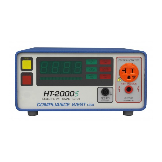
Front Panel Features Before using the HT-S tester, take a few minutes to become familiar with the use of its controls, indicators, and connectors. The front panel features of the HT-S are shown in Figure 1 and Figure 2 then described in Table 2. Figure 1. - Page 15 Figure 2. Front Panel Controls, Indicators and Connectors for HT-4200S.
- Page 16 Table 2. Front Panel Controls, Indicators and Connectors. ITEM NAME FUNCTION When lit, indicates that the HT-S tester is unarmed. This button must be pushed before the TEST button is functional. RESET Button / Red Indicator When the RESET button is pressed, the red RESET indicator goes out and the yellow TEST indicator is lit. PRESSING THE RESET BUTTON AT ANY TIME STOPS THE TEST.
-
Page 17: Front Panel Features
Front Panel Features Before using the HT-S tester, take a few minutes to become familiar with the use of its controls, indicators, and connectors. The rear panel features of the HT-S are shown in Figure 3 and described in Table 3. Figure 3. - Page 18 Table 3. Panel Controls, Indicators and Connectors. ITEM NO. NAME FUNCTION Appliance Inlet / Fuse holder Use supplied cord set to connect tester to appropriate source of supply. Replace line fuse. Turn Tester ON/OFF. Power Switch Power switch must be accessible during operation Fuse replacement warning / Rating Specifies replacement fuse and required supply voltage.
-
Page 19: Options
Options Isolation Relay Interface (PN:00-RI) The Isolation Relay Interface option is a Female DB-15 connector located on the rear panel of the tester. The Isolation Relay Interface option allows the user to manipulate the machine thru the DB-15 connector using a PLC or any other control system that can supply 5V, 12, or 24V depending on the user specification when purchasing the tester. -
Page 20: Section 3
The HT-S tester is shipped in a special protective container that should prevent damage to the instrument during shipping. Check the shipping order against the contents of the container and report any damage or incomplete shipment to Compliance West USA. The container should include the following, pictures are showed in Table : HT-S Dielectric Withstand Tester 18 AWG Line Power Cord. -
Page 21: Fuse Replacement
The following procedure will verify that the HT-S is working correctly. We recommend that this procedure be conducted periodically to ensure proper operation of the tester. (A Compliance West HTT-1 or HTT-1R function tester may also be used to verify the HT-S is working correctly). -
Page 22: Excess Leakage Performance Test
Passage of these tests indicates that the HT-S tester is functioning properly and that it is safe to use. If the results of the performance test are not in accordance with the above, service is required. Remove the HT-S tester from service and contact Compliance West USA, Inc. for servicing information. -
Page 23: Setting Up The Ht-S For Production Line Testing
If the factory settings are acceptable, you may skip this section. Factory Settings The unit is configured as shown when shipped from Compliance West USA as it shown it in Table Table 6. Factory Settings. HT-4200S, HT-3000S, HT-2000S... -
Page 24: Display Setting Limits For Leakage, Time And Ground Continuity
Display Setting Limits for Leakage, Time and Ground Continuity To view the Test Duration, Leakage limit and Ground Continuity limit, hold down the RESET button for 2 seconds, then, the meter will display “L” with the Leakage Limit value in mA. Hold down the RESET button again for 2 seconds and the meter will display “d”... -
Page 25: Adjustment Of High Voltage Ramp Time
To set the leakage limit follow the steps below: Connect the HT-S to a correctly rated source of supply and turn the power switch to the I or ON position. Push the RESET button. The yellow TEST indicator should light, indicating that the HT-S is ready to test. -
Page 26: Adjustment Of Ground Continuity Offset
On the rear panel turn the Ground Resistance potentiometer, as soon as the potentiometer starts turning, the meter will start blinking, displaying the letter “r” with the new limit value in Ω. Adjustment of Ground Continuity Offset When the Ground Continuity test is activated, the offset function may used to compensate for lead and test fixture resistance during the Ground Continuity test. -
Page 27: Ground Continuity Resistance Measurement
Ground Continuity Resistance Measurement NOTE It is recommended to perform the adjustment of the Ground Continuity Offset before measuring the Ground Continuity Resistance. To measure the Ground Continuity Resistance follows the next steps: a. Turn Off the HT-S unit. b. Turn the Ground Check switch on the rear panel to the ON position. c. -
Page 28: Testing A Device With 3-Wire Power Supply Cord
Testing a Device with 3-Wire Power Supply Cord Connect the HT-S unit to a correctly rated source of supply and turn the power switch to the I or ON position. Push the RESET button. The yellow TEST indicator should light, indicating that the HT-S unit is ready to test. -
Page 29: Testing A Device With 2-Wire Power Supply Cord
Testing a Device with 2-Wire Power Supply Cord Connect the HT-S unit to a correctly rated source of supply and turn the power switch to the I or ON position. Push the RESET button. The yellow TEST indicator should light, indicating that the HT-S unit is ready to test. -
Page 30: Section 4
Section 4 Technical Assistance Contact Information Technical Assistance from Compliance West USA is available: Phone: (800) 748-6224 Hours: 8:30 AM - 4:30 PM Pacific Time. Also available on our web site at: www.compwest.com Contact: Compliance West USA 650 Gateway Center Way Suite D San Diego, CA 92102 United States of America. -
Page 31: Maintenance And Calibration
PWB with clean, dry, low pressure (<20 psi). Calibration Information The HT-S series tester has been fully calibrated at the factory in accordance to our published specifications. It is recommended that you have this instrument re-calibrated and safety check done at least once per year.
Need help?
Do you have a question about the HT-S Series and is the answer not in the manual?
Questions and answers