Table of Contents
Advertisement
Quick Links
Advertisement
Table of Contents

Related Manuals for Compliance West MegaPulse 10x700-7PF


Summary of Contents for Compliance West MegaPulse 10x700-7PF
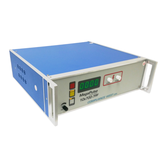
- Page 1 MegaPulse IMPULSE TESTER 10x700-7PF Instruction Manual...
- Page 2 To fully appreciate all the features of your new instrument, we suggest that you take a few moments to review this manual. Compliance West USA stands by your instrument with a full one- year warranty. If the need arises, please don't hesitate to call on Thank you for your trust and confidence.
-
Page 4: Table Of Contents
Figure 1. Controls, Indicators, Connectors – MegaPulse 10x700-7PF Front Panel ..........................8 Table 1. Controls, Indicators, Connectors – MegaPulse 10x700-7PF Front Panel ..9 Figure 2. Controls, Indicators, Connectors – MegaPulse 10x700-7PF Rear Panel ..11 Table 2. Control, Indicators, Connectors – MegaPulse 10x700-7PF Rear Panel ..12 Initial Checkout Procedure ......................13... -
Page 6: An Introduction To Impulse Testing With The Megapulse P Series Tester
Section 1 An Introduction to Impulse Testing with the MegaPulse PF series tester The impulse test is designed to simulate impulse surges which occur in everyday life due to nearby lightning strikes, switching transients, and other high-frequency faults on the power distribution network. -
Page 7: Safety Techniques
Safety Techniques The high voltage circuit of the MegaPulse 10x700-7PF can be shut off at any time by turning OFF the rear power switch. Always press TRIGGER to discharge the tester before turning OFF. The MegaPulse tester is provided with a VOLTAGE ADJUST knob on the front panel. This should always be adjusted to the minimum position at the start of testing. - Page 8 Pressing the POLARITY switch on the front panel can change the polarity of the output waveform. The polarity is Normal when the NOR indicator is lit. In this case, the high voltage will appear on the OUTPUT as a positive pulse relative to the RETURN jack. When the polarity switch is in the Reverse position (REV indicator is lit), the high voltage will appear on the OUTPUT as a negative pulse relative to the RETURN jack.
-
Page 9: Introduction
Your tester is warranted for a period of one year upon shipment of the instrument to the original purchaser. Specifications Specifications for the MegaPulse 10x700-7PF are listed in the table below and the component designations are shown in Figure 1. General diagram. -
Page 10: Operation
Your Tester is shipped in a special protective container that should prevent damage to the instrument during shipping. Check the shipping order against the contents of the container and report any damage or short shipment to Compliance West USA. The container should include the following: •... -
Page 11: Fuse Replacement
Fuse Replacement There is a user-replaceable fuse (F1) located on the rear panel of the instrument. It is located behind a door in the Power Inlet-Power Switch-Fuse Holder device. The fuse rating is noted on the rear panel. Do not attempt to replace it with a fuse of any other rating. Use the following procedure to replace the fuse F1: Turn the power switch to the OFF position. - Page 12 Figure 2. Controls, Indicators, Connectors – MegaPulse 10x700-7PF Front Panel...
- Page 13 ITEM NAME FUNCTION Adjust the digital voltage set point in the tester. VOLTAGE Adjust Knob Press the voltage knob to display the voltage set point. This setting will blink for a few seconds on the front meter. Turn Clockwise to increase the setting Voltage Setting Point before pressing CHARGE button. Toggles the output pulse polarity from Normal to Reverse, Normal for positive and Reverse for Negative, The pulse will appear on the Output jack relative to the return jack POLARITY switch...
- Page 14 MegaPulse is properly grounded. Even though this jack is referenced to ground, it should be treated as hazardous whenever the MegaPulse is turned ON. Table 1. Controls, Indicators, Connectors – MegaPulse 10x700-7PF Front Panel...
- Page 15 Figure 3. Controls, Indicators, Connectors – MegaPulse 10x700-7PF Rear Panel...
- Page 16 FUNCTION Design to cool down the tester. Use supplied cordset to connect the MegaPulse 10x700-7PF tester to an appropriate source of supply. Appliance Inlet / Fuse holder / Fuse holder provides access for Fuse replacement, and the Power Switch is used to turn the tester ON and Power Switch OFF.
-
Page 17: Initial Checkout Procedure
Initial Checkout Procedure The following procedure will verify that the MegaPulse 10x700-7PF tester is working correctly. We recommend that this procedure be conducted periodically to ensure proper operation of the tester. The following items are needed to conduct this procedure: A measuring instrument to monitor the output waveform. - Page 18 Figure 4. Waveform Measurement Setup Testing This section describes how the MegaPulse 10x700-7PF tester is used to conduct a test. The test can be stopped immediately at any time by turning OFF the rear-panel power switch. Connect the tester to a proper source of supply using the included 18 AWG power supply cord.
-
Page 20: Technical Assistance
Section 4 Technical Assistance Technical Assistance from Compliance West USA is available: Phone: (800) 748-6224 Hours: 8:30 AM - 4:30 PM Pacific Time. Also available on our web site at: www.compwest.com Contact: Compliance West USA 2120 Jimmy Durante Blvd, Suite 118 Del Mar, CA., 92014... -
Page 21: Maintenance And Calibration Information
INSTRUCTIONS. Introduction This section of the manual contains maintenance information for the MegaPulse 10x700-7PF impulse tester. A 1-year calibration cycle is recommended to maintain the specifications of the factory. The test equipment required for the performance test is a digital oscilloscope, high voltage oscilloscope probe, digital meter and a high voltage probe. -
Page 22: Calibration Information
Compliance West USA. Voltage Stop Disable / Keyboard Enable by Keyboard. If the MegaPulse 10x700-7PF tester includes TestMinder option and has the Voltage Stop by the PC command activated, it is possible to disable it using the next keyboard sequence: Note: Disabling Voltage Stop enables the keyboard.
Need help?
Do you have a question about the MegaPulse 10x700-7PF and is the answer not in the manual?
Questions and answers