Table of Contents
Advertisement
Quick Links
Advertisement
Table of Contents

Related Manuals for Compliance West MegaPulse D8-PF


Summary of Contents for Compliance West MegaPulse D8-PF
- Page 3 To fully appreciate all the features of your new instrument, we suggest that you take a few moments to review this manual. Compliance West USA stands by your instrument with a full one-year warranty. If the need arises, please do not hesitate to call us.
-
Page 5: Table Of Contents
AC Line Voltage Requirements ..................5 Fuse Replacement ......................5 Section 3 ..............................6 Specifications and Controls ......................6 MegaPulse D8-PF Specifications .................. 6 Front Panel Features...................... 7 Rear Panel Features ....................... 10 General High Voltage Electrical Diagram ..............12 Section 4 .............................. -
Page 7: Section 1
Section 1 Introduction and Safety An Introduction to Impulse Testing with the MegaPulse PF series tester The impulse test is designed to simulate impulse surges which occur in everyday life due to nearby lightning strikes, switching transients, and other high-frequency faults on the power distribution network. Impulse testing is the fundamental method for empirical verification of the adequacy of insulation. -
Page 8: Safety Techniques
Safety Techniques The high voltage circuit of the MegaPulse D8-PF can be shut off at any time by turning OFF the rear power switch. Always press TRIGGER to discharge the tester before turning OFF. The MegaPulse tester is provided with a digital VOLTAGE ADJUST knob on the front panel. This voltage setting should always be confirmed by pressing the VOLTAGE ADJUST knob before starting any test. -
Page 9: Using The Megapulse Pf Impulse Tester
Using the MegaPulse PF Impulse Tester The impulse test involves high voltage and caution should be exercised when using the tester. The RETURN lead is referenced to building ground when properly connected. However, both the OUTPUT and RETURN leads must always be treated as Hazardous whenever the power switch of the MegaPulse is in the ON position. The MegaPulse impulse tester generates the impulse waveform only;... -
Page 10: Section 2
Check the shipping order against the contents of the container and report any damage or short shipment to Compliance West USA. Please save the shipping carton and packing material for the carrier’s inspection. Our customer support department will assist you in the repair or replacement of your instrument. Please do not return your product without first notifying us and receiving an RMA (return material authorization) number. -
Page 11: Ac Line Voltage Requirements
AC Line Voltage Requirements AC line voltage requirements for your Tester are noted on the rear panel of the instrument. Do not connect the instrument to a different voltage source. The cord packaged with your MegaPulse Tester is for use in the United States. -
Page 12: Section 3
Section 3 Specifications and Controls MegaPulse D8-PF Specifications ELECTRICAL Output Voltage: 0 - 5000 V tolerance ±1% Main Capacitance: 32µF ±5% (Dry capacitor type, 2.5 million cycles life) Inductances: 500µH and 25mH ±5% 100Ω, 50Ω and 400Ω ±1% non-inductive. Main Resistances: Voltage Control: Digital Set point adjusted by frontal VOLTAGE knob or by PC TestMinder. -
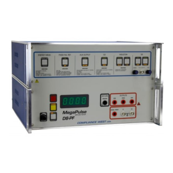
Page 13: Front Panel Features
Before using your Tester, take a few minutes to become familiar with the use of its controls, indicators and connectors. The front panel features of the MegaPulse are shown in Figure 1 and described in Table 1. The rear panel features of the MegaPulse are shown in Figure 2 and described in Table 2. Figure 1 MegaPulse D8-PF Front Panel... - Page 14 When the POLARITY switch is in the Normal position (NOR indicator is lit) the output will be a positive pulse. When the POLARITY switch is in the Reverse position (REV indicator is lit) the output will be a negative pulse. Table 1 MegaPulse D8-PF Front Panel Features...
- Page 15 NAME FUNCTION ITEM The impulse waveform appears on the OUTPUT jack, referenced to the RETURN jack. 400Ω OUTPUT jack When the POLARITY switch is in the Normal position (NOR indicator is lit) the output will be a positive pulse. When the POLARITY switch is in the Reverse position (REV indicator is lit) the output will be a negative pulse. The AUX OUTPUT this output is intended to be used only when it is required to perform a Common Mode test specified in AUX OUTPUT jack IEC80601-2-26:2020.
-
Page 16: Rear Panel Features
Rear Panel Features Figure 2 MegaPulse D8-PF Rear Panel... - Page 17 Appliance Inlet / Fuse holder / Power Use supplied cord set to connect the MegaPulse D8-PF tester to an appropriate source of supply. Fuse Switch holder provides access for Fuse replacement, and the Power Switch is used to turn the tester ON and OFF.
-
Page 18: General High Voltage Electrical Diagram
General High Voltage Electrical Diagram Figure 3 General High Voltage Electrical Diagram– MegaPulse D8-PF... -
Page 19: Section 4
When the Interlock is closed, it enables all normal operations of the MegaPulse D8-PF features. Front Keyboard and Voltage Knob Enable If the MegaPulse D8-PF tester has disabled the keyboard or Voltage Knob, it is possible to enable them by using the next keyboard sequence: Turn OFF the MegaPulse tester. -
Page 20: Polarity Pulse Selection
Charge and Trigger a Pulse The following procedure will explain how to generate a high voltage pulse with the MegaPulse unit. The MegaPulse D8-PF is capable to maintain a specific voltage charge selected by the Voltage Set Point. CAUTION High voltage generated by the MegaPulse tester is exposed during this test. A risk of shock exists. -
Page 21: Pulse Verification Procedure
Pulse Verification Procedure The following procedure will verify that the high voltage pulse is properly generated by the D8-PF tester. We recommend that this procedure be conducted periodically to ensure proper operation of the tester. The following items are needed to conduct this procedure: High voltage oscilloscope probe (1000:1) Digital Oscilloscope Always ensure that the measuring instruments are rated for the voltage and frequency response involved. - Page 22 1000:1 HV Probe Figure 4 Pulse Capture Setup Figure 5 Vpeak = 4.76kV with 500µH inductor Figure 6 Vpeak = 3.92kV with 25mH inductor...
-
Page 23: Energy Measurement
“R” over the test period. Energy Measurement using System Included on D8-PF The MegaPulse D8-PF tester is equipped with an internal high voltage pulse acquisition system connected directly to the internal 100Ω resistor. This system automatically calculates the energy for each single pulse delivered. -
Page 24: Energy Measurement With External Acquisition System
Energy Measurement with external acquisition system The MegaPulse D8-PF tester is equipped with two high voltage connectors located on the rear panel to have access directly to the 100 resistor, allowing energy measurements with an external high voltage acquisition system. -
Page 25: Pass Fail Reference Built In
Pass Fail Reference Built in The Pass-Fail Reference Built in circuit is designed to allow the user to perform a quick check test of the Y1-Y2 measurement system of the D8-PF tester. To perform a quick test using the Pass-Fail Reference Build in follow the next steps: Set the Pass-Fail switch to the ON position. -
Page 26: Section 5
To perform actual testing, the D8-PF should be connected to the EUT as shown in the standard which the EUT is being tested to. See figures 10, 11 and 12; they are examples of the MegaPulse D8-PF connections for testing parameters of IEC60601 and IEC80601-2-26:2020. - Page 27 Figure 11 Example of D8-PF Connections on Figures 9A and 9B of IEC60601 NOTE: All D8-PF meet the specifications of IEC 60601-2-27 ed 3.0 where a 390kΩ resistor replaced the 470kΩ.
- Page 28 – 2 – IEC 80601-2-26:2019/COR1:2021 IEC 2021 Figure 201.101 – Test of protection against the effects of defibrillation (common mode) Replace the existing figure with the following new figure: Components G sine wave generator 10 Hz high voltage source 5 kV DC Ⓕ...
-
Page 29: Section 6
Section 6 Options This section contains a list of available options for D8-PF. Option Name Description For different Line voltages replace xxx on the part number with 100, 110, 220, 230 or 00-MPxxx 240 depending on the line voltage. (120V for standard configuration). 00-34 Incorporates a circuit for Invasive Blood Pressure test (IEC 60601-2-34 Issue 2) HV jumper to disconnect the internal 100ohm resistor and use external Energy... -
Page 30: 100X - External Energy Measurement Capability Option
Press the TRIGGER button to discharge the tester and make sure the front meter display reads a safe low voltage. 10. Turn OFF the MegaPulse D8-PF. 11. Remove the 100X Jumper in the rear panel for external load. 12. Connect an external load at the Energy Measurement and Ground connectors. -
Page 31: 00-Sg - Sine Wave Generator Option
00-SG - Sine Wave Generator Option The Sine Wave Generator option is offered as a separate upgrade to the unit. The sine wave is adjustable and must be set up using an oscilloscope. The Sine Wave Generator signal characteristics are defined as follows: •... -
Page 32: 00-D8-Pf-Sdo - Safety Discharge Option
00-D8-PF-SDO - Safety Discharge Option The Safety Discharge Option incorporates an Emergency Stop Switch, Main Capacitor discharge circuit, Outputs isolation relay, Power ON LED indicator. The Safety Discharge Option works as follow: Main Capacitor will be internally discharge and outputs will be isolated from panel when one of the following scenarios occur: Loss of power When losing power, the SDO drains the main capacitor internally and disconnects outputs. -
Page 33: Section 7
Service Information The MegaPulse D8-PF tester is warranted to the original purchaser for a period of 1 year. This warranty does not cover problems due to misuse or neglect. Malfunctions which occur within the limits of the warranty will be corrected at no charge. -
Page 34: Technical Assistance
Technical Assistance Technical Assistance from Compliance West USA is available: Phone: (800) 748-6224 Hours: 8:00 AM - 4:00 PM Pacific Time. Also, available on our web site at: www.compwest.com Contact: Compliance West USA 650 Gateway Center Way, Suite D San Diego, CA., 92102 United States of America.
Need help?
Do you have a question about the MegaPulse D8-PF and is the answer not in the manual?
Questions and answers