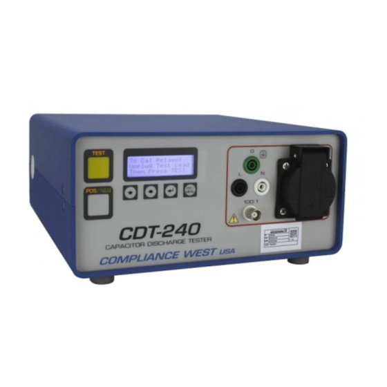
Compliance West CDT-240 Instruction Manual
Capacitor discharge tester with cbx built in
Hide thumbs
Also See for CDT-240:
- Calibration procedure (12 pages) ,
- Factory calibration procedure (13 pages)
Table of Contents
Advertisement
Advertisement
Table of Contents

Related Manuals for Compliance West CDT-240


Summary of Contents for Compliance West CDT-240
- Page 1 CDT-240 CAPACITOR DISCHARGE TESTER WITH CBX BUILT IN Instruction Manual...
- Page 4 Dear Customer: Congratulations! Compliance West USA is proud to present you with your CDT-240 Capacitor Discharge Tester with CBX built in. Your instrument features a logic-controlled circuit for a Residual Voltage Meter. To fully appreciate all the features of your new meter, we suggest that you take a few moments to review this manual.
-
Page 6: Table Of Contents
Table of Contents Section 1 ..................................2 Introduction and Safety ..........................2 An Introduction to Residual Voltage measurements with CDT-240 Tester ........2 Safety Precautions ........................2 Test Personnel ..........................2 Testing Area ..........................2 Safety Techniques ........................2 Section 2 ..................................3 Getting Started.............................. -
Page 8: Section 1
The CDT-240 tester can connect to voltages in excess of 264V at potentially lethal current levels. Currents of as little as 5mA at 120 volts can cause death; the CDT-240 can pass through currents of more than 8 Amps. The potential for serious injury or death exists and personnel should be aware when they conduct this test. -
Page 9: Section 2
The first fuse is located on the bottom right side behind a door in the Inlet-Power Switch- Fuse Holder device. This fuse protects the internal circuitry of the CDT-240. Do not attempt to replace it with a fuse of any other rating. Use the following procedure to replace the fuse: •... -
Page 10: Section 3
TESTING CIRCUITRY Minimum / Maximum Test Voltage 90Vrms min/ 270Vrms max Maximum Test Current 8A for CDT-240 8A / or CDT-240 15A option Fuse (CDT-240 8A option) 10A, 250V, time delay, 1-¼" x ¼" Fuse (CDT-240 15A option) 20A, 250V, time delay, 1-¼" x ¼"... -
Page 11: Front Panel Features
Front Panel Features Before using the CDT-240 tester, take a few minutes to become familiar with the use of its controls, indicators, and connectors. The front panel features of the CDT-240 tester are shown on Figure 3.1 and described in Table 3.1. -
Page 12: Rear Panel Features
Rear Panel Features Before using the CDT-240 tester, take a few minutes to become familiar with the use of its controls, indicators, and connectors. The rear panel features are shown on Figure 3.2 and described in Table 3.2 Figure 3.2 Rear Panel Controls, Indicators and Connectors... -
Page 13: Factory Settings
Factory Settings. The CDT-240 comes with the factory setting described on table 3.3 LOCATION STANDARD TEST TYPE VOLTAGE TIME TRIGGER REFERENCE EDITABLE IEC 60950 Delay 3.0s Negative Memory 1 Memory 2 * IEC 60950 Voltage 50.0V Positive Memory 3 IEC 60950 Delay 1.0s... -
Page 14: Section 4
(for example, measure the residual voltage one second after the power is disconnected). The Voltage Test allows the CDT-240 to measure the elapsed time until the voltage has dropped from the peak of the AC voltage (when power to the EUT is disconnected) to a specific voltage level. -
Page 15: Starting The Cdt-240
Starting the CDT-240 1. Connect the voltage input. Plug the CDT-240 to a main voltage supply. See image below 2. Connect the TEST VOLTAGE INPUT with the desired test voltage. See image below (2) 3. The tester requires to run the calibration on every start up. -
Page 16: Main Menu
Main Menu The main menu includes 3 options, use ▲ and ▼ buttons and press ENTER (RTN) to select. CURRENT TEST - To view current test settings. EDIT MEMORY - To edit a memory setting. STANDARDS - Displays the pre-set standards available. -
Page 17: Edit Memory
Edit Memory Use this option to edit the settings saved in a specific memory. The preset standards parameters can’t be edited, refer to table 3.3 for factory settings and standard parameters. Standard 1 for IEC 61010, standard 2 for IEC 60065 and Standard 3 for IEC 60335. 1. - Page 18 g. To change the Delay time, select the Delay = “seconds” from the EDIT MEMORY menu. (left image) h. Use ▲ and ▼ buttons to set the time in seconds and press ENTER (RTN). (right image below) If voltage test is selected the time can’t be changed. i.
-
Page 19: View Available Standards
Warning: The voltage will be present on the front panel output when ARMED. (left image below) 5. Press TEST again and the CDT-240 will run the test. 6. After the test is finished the result of the test will be displayed. (right image below) -
Page 20: Bnc Setup And Operation
BNC Setup and Operation The CDT-240 is equipped with a BNC 100:1 output. This output signal can be connected to an oscilloscope for reference. In the oscilloscope can be captured the residual voltage in the EUT. A straight-through BNC-to-BNC cable can be used to connect the BNC output of the CDT-240 to the Channel 1 input of an oscilloscope. -
Page 21: Testing Iec 60950
1 second (for normal equipment with a power cord). This measurement can be accomplished by the CDT-240 in two ways: - Select a Voltage Test, and set the Voltage level to 37% of the peak voltage level. For example, if testing at 240Vrms, the peak voltage is 340 Volts (1.41 x 240). - Page 22 - Select a Delay Test, and set the Delay time to 1 second. If testing at 240Vrms, the peak voltage is 340 Volts (1.41 x 240). 37% of 340 is 126 Volts. When the test is performed, if the voltage measured after a 1 second delay is less than 126 Volts, the EUT meets the requirement of IEC 60950.
-
Page 23: Testing Line To Neutral Only
Testing Line to Neutral Only The standards generally dictate that the capacitor discharge (stored energy at mains connection) test only be conducted if the capacitance is greater than 0.1uF. The implied premise is that capacitors smaller than this value do not present a significant shock hazard because the stored energy is small. -
Page 24: Section 5
1. Unplug all the test leads from the front panel of the CDT-240. 2. Connect the CDT-240 to the main power. 3. Connect the Test Voltage input on the back of the CDT-240. We recommend 120V for this test. 4. Turn on the CDT-240. -
Page 25: Section 6
Section 6 Technical Assistance Contact Information Technical Assistance from Compliance West USA is available: Phone: (800) 748-6224 Hours: 8:30 AM - 4:30 PM Pacific Time. Also available on our web site at: www.compwest.com Contact: Compliance West USA 650 Gateway Center Way Suite D San Diego, CA 92102 United States of America. -
Page 26: Section 7
CONTAINED IN THE OPERATING INSTRUCTIONS UNLESS YOU ARE QUALIFIED TO DO Service Information The CDT-240 Tester is warranted to the original purchaser for a period of 1 year. This warranty does not cover problems due to misuse or neglect. Malfunctions which occur within the limits of the warranty will be corrected at no charge. -
Page 27: Impedance Evaluation
S: Tektronix DPO3012 oscilloscope and Tektronics P6015 1000x probe : Resistance of scope and probe, 100 MOhm : Capacitance of scope and probe, 3pF E: Equipment being evaluated, Compliance Products CDT-240 : Resistance of equipment being evaluated : Capacitance of equipment being evaluated... -
Page 28: Theory Of Operation
Appendix B Theory of Operation: Theory: Because the equipment being evaluated has active circuitry, it is not possible to make accurate measurements using an LCR meter or similar instruments. The equipment being evaluated must be energized (turned on) and configured in the appropriate state so that the true input impedance of the circuitry is presented. - Page 29 Test Voltage Circuit Configuration Measured Comments Source Connected Voltage (RMS) AC (a) scope only Voltage on the source (open side of RD will be about circuit) twice as high DC (b) scope only 50.8 Voltage on the source (open side of RD will be about circuit) twice as high AC (a)
-
Page 30: Ctl Decision Sheet P-Dsh-0716
Appendix C CTL Decision Sheet P-DSH-0716... -
Page 31: Measuring Neutral To Ground
EUT is connected to "L" on the CDT-240, and the "Line" designated terminal is connected to "N" on the CDT-240. In this case, the CDT-240 should be set up to measure from Line to Ground (not Neutral to Ground). - Page 32 50V Pass/Fail threshold, this would require a measurement guard-band of 47.5 to 52.5V. At 50V, the measurement guard-band of the CDT-240 is 48.2 to 51.8V (+/- 2% +/- 0.8V): +/- 3.6% of the measured voltage. In fact, the CDT-240 is capable of measuring voltages as low...
- Page 33 Table E1: Comparison of tolerance specifications over the measured voltage range Table E2: Comparison of tolerance specifications as a percentage of measured voltage...
Need help?
Do you have a question about the CDT-240 and is the answer not in the manual?
Questions and answers