Table of Contents
Advertisement
Quick Links
Advertisement
Table of Contents

Related Manuals for Compliance West MegaPulse D5-PF


Summary of Contents for Compliance West MegaPulse D5-PF
- Page 3 To fully appreciate all the features of your new instrument, we suggest that you take a few moments to review this manual. Compliance West USA stands by your instrument with a full one-year warranty. If the need arises, please don't hesitate to call on us.
-
Page 4: Table Of Contents
AC Line Voltage Requirements ....................5 Fuse Replacement ........................5 Section 3 ..............................6 Specifications and Controls ........................6 MegaPulse D5-PF Specifications ....................6 Front and Rear Panel Features ..................... 7 General High Voltage Electrical Diagram................... 12 Section 4 ..............................13 Operating Instructions .......................... - Page 5 Cleaning ........................26 Calibration Information ....................... 26 Technical Assistance ........................27...
-
Page 7: Section 1
Section 1 Introduction and Safety An Introduction to Impulse Testing with the MegaPulse PF series tester The impulse test is designed to simulate impulse surges which occur in everyday life due to nearby lightning strikes, switching transients, and other high-frequency faults on the power distribution network. Impulse testing is the fundamental method for empirical verification of the adequacy of insulation. -
Page 8: Safety Techniques
Safety Techniques The high voltage circuit of the MegaPulse D5-PF can be shut off at any time by turning OFF the rear power switch. Always press TRIGGER to discharge the tester before turning OFF. The MegaPulse tester is provided with a digital VOLTAGE ADJUST knob on the front panel. This voltage setting should always be confirmed by pressing the VOLTAGE ADJUST knob before starting any test. -
Page 9: Using The Megapulse Pf Impulse Tester
Using the MegaPulse PF Impulse Tester The impulse test involves high voltage and caution should be exercised when using the tester. The RETURN lead is referenced to building ground when properly connected. However, both the OUTPUT and RETURN leads must always be treated as Hazardous whenever the power switch of the MegaPulse is in the ON position. The MegaPulse impulse tester generates the impulse waveform only;... -
Page 10: Section 2
Section 2 Getting Started This section contains information for the unpacking, inspection, preparation for use and storage of your Compliance West product. Unpacking and Inspection Packaging Your Tester is shipped in a special protective container that should prevent damage to the instrument during shipping. Check the shipping order against the contents of the container and report any damage or short shipment to Compliance West USA. -
Page 11: Ac Line Voltage Requirements
Please contact Compliance West USA (1-800-748-6224) to inform about the service for your instrument. AC Line Voltage Requirements AC line voltage requirements for your Tester are noted on the rear panel of the instrument. Do not connect the instrument to a different voltage source. The cord packaged with your MegaPulse Tester is for use in the United States. -
Page 12: Section 3
Section 3 Specifications and Controls MegaPulse D5-PF Specifications ELECTRICAL Output Voltage: 0 - 5000 V tolerance ±1% Main Capacitance: 32 uF ±5% (Dry capacitor type, 2.5 million cycles life) Inductances: 500uH and 25 mH ±5% 100 Ω, 50 Ω and 400 Ω ±1% non-inductive. -
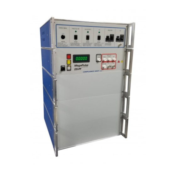
Page 13: Front And Rear Panel Features
Before using your Tester, take a few minutes to become familiar with the use of its controls, indicators and connectors. The front panel features of the MegaPulse are shown in Figure 1 and described in Table 1. The rear panel features of the MegaPulse are shown in Figure 2 and described in Table 2. Figure 1 Controls, Indicators, Connectors – MegaPulse D5-PF Front Panel... - Page 14 ITEM NAME FUNCTION Adjust the digital voltage set point in the tester. VOLTAGE Adjust Knob Press the voltage knob to display the voltage set point. This setting will blink for a few seconds on the front meter. Turn Clockwise to increase the Voltage Setting Point before pressing CHARGE button. Toggles the output pulse polarity from Normal (Positive) to Reverse (Negative).
- Page 15 It is used to adjust the amplitude of the sine waveform. Only for models with Sine Wave Generation option. FINE adjustment (optional) It is used to fine adjust the amplitude of the sine waveform. Only for models with Sine Wave Generation option. Table 1. Controls, Indicators, Connectors – MegaPulse D5-PF Front Panel...
- Page 16 Figure 2. Controls, Indicators, Connectors – MegaPulse D5-PF Rear Panel...
- Page 17 Appliance Inlet / Fuse holder / Use supplied cord set to connect the MegaPulse D5-PF tester to an appropriate source of supply. Fuse Power Switch holder provides access for Fuse replacement, and the Power Switch is used to turn the tester ON and OFF.
-
Page 18: General High Voltage Electrical Diagram
General High Voltage Electrical Diagram Figure 3. General High Voltage Electrical Diagram– MegaPulse D5-PF... -
Page 19: Section 4
When the Interlock is closed, it enables all normal operations of the MegaPulse D5-PF features. Front Keyboard and Voltage Knob Enable If the MegaPulse D5-PF tester has disabled the keyboard or Voltage Knob, it is possible to enable them by using the next keyboard sequence: Turn OFF the MegaPulse P tester. -
Page 20: Polarity Pulse Selection
Disconnect the high voltage cables from the outputs connectors (50 ohm, 400 ohm, Aux Output, Energy Measurement point and 50K ohm “If included”). Turn the rear-panel Power Switch ON. Press the red TRIGGER button to discharge the main capacitor into the internal resistor of the MegaPulse unit. -
Page 21: Pulse Verification Procedure
Push the yellow CHARGE button to start charging the internal high voltage capacitor and wait until the front meter reaches value set on Steps 1 or 2. Verify that the red TRIGGER indicator is now lit. Once the desired voltage is reached, press the red TRIGGER button to deliver the high voltage pulse (be sure not to touch the output and return leads when pressing the trigger switch). - Page 22 Trigger Level = -1kV. Slope transition “High to Low” 19. Charge and Trigger the pulse at 5000V. Push the yellow CHARGE button to start charging the internal high voltage capacitor. Once the desired voltage is reached, press the red TRIGGER button to deliver the pulse (be sure not to touch the output and return leads when pressing the trigger switch).
- Page 23 Figure 7. Y1 Y2 Test Output...
-
Page 24: Energy Measurement
Energy Measurement using System Included on D5-PF The MegaPulse D5-PF tester is equipped with an internal high voltage pulse acquisition system connected directly to the internal 100 ohm resistor. This system automatically calculates the energy for each single pulse delivered. -
Page 25: Energy Measurement With An External Acquisition System
Energy Measurement with an External Acquisition System The MegaPulse D5-PF tester is equipped with two high voltage connectors located on the rear panel to have access directly to the 100 resistor, allowing energy measurements with an external high voltage acquisition system. The acquisition system must be capable of executing the advanced mathematical formula shown on figure 8. - Page 26 Set S3 to “Open” position. Select Inductor switch to the 500uH. Only if option 100X is included on the D5-PF tester, install the 100X jumper on the rear panel. Only if option 34 is included on the D5-PF tester: set the time switch to 200mS Install the 50k...
-
Page 27: Section 5
See figures 11 and 12 are examples of the MegaPulse D5-PF connections for testing parameters of IEC60601. They can be used as a key for the inputs and outputs of the MegaPulse D5-PF. Note the actual connections on the front panel of the D5-PF have been added to Figure 50 of IEC 601for illustrative purposes. - Page 28 NOTE: All D5-PF meet the specifications of IEC 60601-2-27 ed 3.0 where a 390KΩ resistor replaced the 470KΩ. Figure 12. Example of D5-PF Connections on Figures 9A and 9B of IEC60601...
-
Page 29: Section 6
Section 6 Options This section contains a list of available options for D5-PF. Option Name Description Incorporates a circuit for Invasive Blood Pressure test (IEC 60601-2-34 Issue 2) HV jumper to disconnect the internal 100ohm resistor and use external Energy 100X measurement devices like Fluke 7000DP and 7010. -
Page 30: Sine Wave Generator
Press the TRIGGER button to discharge the tester and make sure the front meter display reads a safe low voltage. 10. Turn OFF the MegaPulse D5-PF. 11. Remove the 100X Jumper in the rear panel for external load. 12. Connect an external load at the Energy Measurement and Ground connectors. -
Page 31: Vacuum Trigger Relay
Figure 13. Sine Wave Generator option To operate the Sine Wave Generator option follows the next steps: Put the S2 switch in the SINE WAVE position. Attach the 10 Hz sine wave BNC output to an oscilloscope with a 1MΩ impedance input. Adjust the sine wave amplitude using the coarse and fine adjustments. -
Page 32: Section 7
Service Information The MegaPulse D5-PF tester is warranted to the original purchaser for a period of 1 year. This warranty does not cover problems due to misuse or neglect. Malfunctions which occur within the limits of the warranty will be corrected at no charge. - Page 33 Technical Assistance Technical Assistance from Compliance West USA is available: Phone: (800) 748-6224 Hours: 8:00 AM - 4:00 PM Pacific Time. Also, available on our web site at: www.compwest.com Contact: Compliance West USA 650 Gateway Center Way, Suite D San Diego, CA., 92102 United States of America.
Need help?
Do you have a question about the MegaPulse D5-PF and is the answer not in the manual?
Questions and answers