
Related Manuals for Compliance West HT-2800P


Summary of Contents for Compliance West HT-2800P
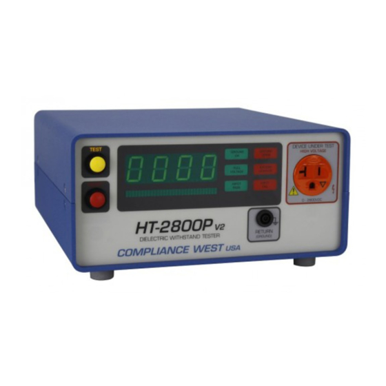
- Page 1 HT-2800P Dielectric Withstand Tester 0-2800 Volts DC Output Instruction Manual COMPLIANCE WEST...
- Page 3 Dear Customer: Congratulations! Compliance West USA is proud to present you with your Dielectric Withstand Tester. Your instrument features a groundbreaking logic-controlled circuit design and ergonomic front panel, and represents the latest in high voltage production line testing. To fully appreciate all the features of your new meter, we suggest that you take a few moments to review this manual.
-
Page 5: Table Of Contents
Table of Contents An Introduction to Dielectric Withstand Testing with the HT-2800P ............4 Safety Precautions ........................4 Test Personnel........................4 Testing Area........................4 Safety Techniques ......................5 Using the HT-2800P Dielectric Withstand Tester................5 Ground Check ........................5 Ground Check Failures ..................5 Defeating the Ground Check ................6 Leakage Test ........................6... -
Page 6: An Introduction To Dielectric Withstand Testing With The Ht-2800P
Currents of as little as 5 mA at 120 volts can cause death, and the HT- 2800P is capable of generating 5 mA at up to 2800 volts. The HT-2800P has been designed to minimize exposure to high voltages. However, the potential for serious injury or death exists and personnel should be aware when they conduct this test. -
Page 7: Safety Techniques
Safety Techniques The high voltage circuit of the HT-2800P can be shut off at any time by pressing the RESET button. The HT-2800P has been provided with a Reset switch to provide an unarmed "Standby" setting when it is energized, but idle. When the red RESET button is lit, the tester will not provide high voltage until the RESET button and the TEST button have been pressed in order. -
Page 8: Defeating The Ground Check
HT-2800P may show a "PASS". To allow the HT-2800P to test equipment using a two wire power supply cord, the Ground Check can be defeated by turning the rear panel Ground Check switch to the Off position. -
Page 9: Sporadic Leakage Current Failures
If the green Hipot Pass LED lights, the test cycle has been successfully completed. The equipment under test is in accordance with the preset test parameters. The HT-2800P is ready to test the next piece of equipment. -
Page 10: High Voltage Dielectric Withstand Test Failures
Testing Equipment with non-Standard Plugs or Pigtail Operation The front panel of the HT-2800P is provided with a NEMA Type 5-15R receptacle, suitable for testing cord-equipped single-phase products designed for use on a 15 amp branch circuit in North America. -
Page 11: Introduction And Specifications
This manual contains complete operating, maintenance and calibration instructions for the Compliance West USA Model HT-2800P Dielectric Withstand Tester. The HT-2800P is a bench-type Dielectric Withstand Tester with DC Output, designed for production line testing. The HT-2800P features automatic one button operation, with numerous safety features designed to protect the operator: The Return Lead is directly connected to ground potential for operator safety. - Page 12 Leakage Test Provided; 2 mA factory set pass/fail point, user adjustable. Operation Instructions Provided on rear panel. Table 1. HT-2800P Specifications *Ground Continuity Pass/Fail Level can be adjusted from .5 to 5 ohms during the calibration procedure.
-
Page 13: Operation
Before using your tester, take a few minutes to become familiar with the use of its controls, indicators, and connectors. The front panel features of the HT-2800P are shown in Figure 2 and described in Table 2. The rear panel features of the HT-2800P are shown in Figure 3 and described in Table 3. - Page 14 Figure 2. Controls, Indicators, Connectors - Model HT-2800P Front Panel...
- Page 15 RESET Button / Red Indicator When lit, indicates that the HT-2800P is unarmed. This button must be pushed before the TEST Button is functional. When the RESET Button is pressed, the red RESET indicator goes out and the yellow TEST indicator is lit.
- Page 16 Figure 3. Controls, Indicators, Connectors - Model HT-2800P Rear Panel...
- Page 17 Use supplied cord set to connect tester to appropriate source of supply. Replace line fuse. Turn Tester Power Switch ON/OFF. Fuse replacement warning / Specifies replacement fuse and required supply voltage. Rating of supply Table 3. Controls, Indicators, Connectors - Model HT-2800P Rear Panel...
-
Page 19: Initial Checkout Procedure
The following procedure will verify that the HT-2800P is working correctly. We recommend that this procedure be conducted periodically to ensure proper operation of the tester. (A Compliance West HTT-1 function tester may also be used to verify the HT-2800P is working correctly.) The following items are needed to conduct this procedure: - A three inch piece of 18 AWG insulated hookup wire with each end stripped back ½". -
Page 20: Setting Up The Ht-2800P For Production Line Testing
This section describes procedures for setting the Pass/Fail leakage current level, high voltage ramp time, high voltage level, and high voltage test time. The HT-2800P is calibrated as shown below at the factory to be usable without adjustment in the majority of applications. If the factory settings are acceptable, you may skip this section. -
Page 21: Display Of Leakage Limit And Duration Settings
Most safety agencies will allow a shorter test (usually 1 sec. vs. 1 min.) if the voltage is increased by 20%. The HT-2800P is factory set for 1700 volts, a voltage level used for the one second test for many types of equipment. Consult the safety agencies for the required voltage level for the type of equipment being tested. -
Page 22: Setting The Ground Check Switch
(usually 1 second vs. 1 minute) if the voltage is increased by 20%. The HT-2800P is factory set for 2 seconds. Consult the safety agencies for the test time for the type of equipment being tested. If a different test time is required, use this procedure to set it. -
Page 23: Daily Operation Test
The operation of the HT-2800P should be audited daily by conducting the tests described in the Initial Checkout Procedure section of this Manual. Compliance West also offers the model HTT-1, which can be used to quickly verify the operation of your HT-2800P. Contact the factory for details. -
Page 24: Test Results
This will ensure that the test voltage has been bled off. The operator can now remove the equipment from the HT-2800P and connect another. The HT-2800P should then be armed by pressing the RESET button. When ready, the operator then presses the TEST button and the test procedure will be conducted again. -
Page 25: Technical Assistance
Technical Assistance For Technical Assistance Phone: (800) 748-6224 Technical Assistance is available from Compliance West USA between the hours of 8:30 AM and 4:30 PM Pacific Time. Compliance West USA 2120 Jimmy Durante Blvd., Suite 118 Del Mar, CA 92014... -
Page 27: Maintenance And Calibration
Service Information The HT-2800P is warranted to the original purchaser for a period of 1 year. This warranty does not cover problems due to misuse or neglect. Malfunctions which occur within the limits of the warranty will be corrected at no charge. -
Page 28: Calibration Access
Calibration Access Use the following procedures to gain access to the calibration adjustments of your instrument. 1. Set Line Power switch to OFF. 2. Disconnect the power cord from the rear of the instrument. 3. Remove the two upper screws on each side of the unit. 4. -
Page 29: Voltage Calibration Adjustment
LED has been attained. Voltage Calibration Adjustment Use the following procedure to calibrate the output voltage. Ensure that all test leads are removed from the HT-2800P. Turn OFF the HT-2800P tester. To enter the Calibration Mode you MUST follow the following sequence: - Hold in both the Test and Reset buttons. - Page 30 10. Press the Reset button until "V2" is displayed on the front panel meter. 11. Turn the Voltage Adjust on the rear panel to minimum (counterclockwise). Press the Test button and 500 will be displayed on the front panel meter. Be careful as the HT-2800P will be putting out voltage at this point.
Need help?
Do you have a question about the HT-2800P and is the answer not in the manual?
Questions and answers