Shinko JCL-33A Instruction Manual
Icro-computer based
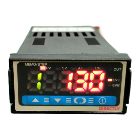
digital indicating controller
Hide thumbs
Also See for JCL-33A:
- Instruction manual (32 pages) ,
- Communication instruction manual (36 pages)
Table of Contents
Advertisement
Quick Links
Advertisement
Table of Contents

Related Manuals for Shinko JCL-33A


Summary of Contents for Shinko JCL-33A
- Page 1 MICRO-COMPUTER BASED DIGITAL INDICATING CONTROLLER JCL-33A INSTRUCTION MANUAL...
- Page 2 • Any unauthorized transfer or copying of this document, in part or in whole, is prohibited. • Shinko Technos CO., LTD. is not liable for any damages or secondary damages incurred as a result of using this product, including any indirect damages.
- Page 3 Caution • Use the solderless terminal with an insulation sleeve that fits in the M3 screw when wiring the JCL-33A Series. • The terminal block of this instrument is designed to be wired from the left side. The lead wire must be inserted from the left side of the terminal, and fastened with the terminal screw.
-
Page 4: Table Of Contents
--- CONTENTS --- 1. Model name 1.1 Model name -------------------------------------------------------------------------- 5 1.2 How to read the model nameplate --------------------------------------------- 5 2. Name and functions of the sections ------------------------------------- 5 3. Mounting to control panel 3.1 Site selection ------------------------------------------------------------------------- 6 3.2 External dimensions ---------------------------------------------------------------- 6 3.3 Panel cutout -------------------------------------------------------------------------- 6 3.4 Mounting ------------------------------------------------------------------------------ 6 4. -
Page 5: Model Name
1. Model name 1.1 Model name JCL– 33 A Series name: JCL-33A (W48 x H24 x D98.5mm) Alarm action can be selected by keypad. *1 Relay contact: 1a Non-contact voltage (for SSR drive): 12 V DC (Control +2 0 output) -
Page 6: Mounting To Control Panel
3. Mounting to control panel 3.1 Site selection This instrument is intended to be used under the following environmental conditions (IEC61010-1): Overvoltage category , Pollution degree 2 Ensure the mounting location corresponds to the following conditions: • A minimum of dust, and an absence of corrosive gases •... -
Page 7: Wiring Connection
4. Wiring connection Warning Turn the power supply to the instrument off before wiring. Working or touching the terminal with the power switched on may result in severe injury or death due to Electric Shock. • POWER SUPPLY: Power terminals •... -
Page 8: Setup
Input: K –200 to 1370 , Alarm 1 (A1): No alarm action, Alarm 2 (A2): No alarm action, Reverse (Heating) control action If the users’ specification is the same as the default value of the JCL-33A, it is not necessary to set up the controller. Proceed to Section “6.1 Main setting mode”. - Page 9 Auxiliary function setting mode 2 Display Item, Function, Setting range Default value Input type selection (-200 to 1370 ) • The input type can be selected from thermocouple (10 types), RTD (2 types), DC current (2 types) and DC voltage (4 types). The unit can be selected as well.
- Page 10 PV filter time constant setting 0.0 seconds • Sets PV filter time constant. Input fluctuation due to the noise can be reduced. If the value is set too large, it affects control result due to the delay of response. • Setting range: 0.0 to 10.0 seconds OUT high limit setting 100% •...
- Page 11 A2 action selection No alarm action • Selects an action for A2. • Action selection and default value are the same as those of A1 action selection. A1 hysteresis setting • Sets hysteresis for A1. • Not available if No alarm action, Timer function or Pattern end output is selected during A1 action selection •...
- Page 12 Delay action type selection ON delay • Selects a delay action type for Timer function. • Available only when Timer function is selected during A1 and A2 action selection. • : ON delay : OFF delay : ON/OFF delay (Contact Closed) DI input (Contact Open) ON delay...
- Page 13 : Output OFF : Output ON Controller/Converter function selection Controller • Selects whether to use the JCL-33A as a controller or a converter. If the JCL-33A is switched from a converter to a controller, control parameters which were automatically set when converter function was selected are maintained as they were.
-
Page 14: Operation
6. Operation 6.1 Main setting mode To go to the main setting mode, press the key in the PV/SV display mode. Set each setting item with the key, and register the value with the key. In the main setting mode, setting items are different depending on the instrument status. •... - Page 15 Step 4 step time setting 00:00 • Sets step 4 step time. • Available only when program control function is selected during OUT/OFF key function selection • Setting range: 00:00 to 99:59 Step 5 step SV setting • Sets step 5 step SV. •...
-
Page 16: Sub Setting Mode
6.2 Sub setting mode To go to the Sub setting mode, press the key while pressing key in the PV/SV display mode. Set each setting item with the key, and register the value with the key. Display Item, Function, Setting range Default value AT (Auto-tuning) selection AT Cancel... -
Page 17: Auxiliary Function Setting Mode
Shinko protocol • Selects the communication protocol. • Available only when the option C5 is applied. • : Shinko protocol, : Modbus ASCII mode, : Modbus RTU mode Instrument number setting • Sets the instrument number individually to each instrument when communicating by connecting plural instruments in serial communication. -
Page 18: Running
After the controller has been mounted to the control panel and wiring is completed, it can be started in the following manner. (1) Turn the power supply to the JCL-33A ON. For approx. 3s after the power is switched ON, the sensor input character and the temperature unit are indicated on the PV/SV display. -
Page 19: Mv (Control Output Manipulated Variable) Indication
To release MV indication function, press the key again or turn the power of the JCL-33A off and on again. 7.3 Control output OFF function This is a function to pause the control action or to turn the control output of the unused instrument of the plural units OFF even if the power to the instrument is supplied. -
Page 20: Operation Flowchart
8. Operation flowchart PV indication when SV is PV/SV display mode Automatically Control output OFF selected, and vice versa PV indication during program returns 2s later. Press the (Fixed value control) control standby MEMO/STEP display is unlit. for 1 second. Press the key. - Page 21 Input type (Character indication) and range Alarm action types (High limit alarm): The alarm action is deviation setting to the SV. The alarm is -200 to 1370 -320 to 2500 activated if the input value reaches the high limit setting value. -199.9 to 400.0 -199.9 to 750.0 (Low limit alarm): The alarm action is...
-
Page 22: Pid Auto-Tuning
9. PID auto-tuning In order to set each value of P, I, D and ARW automatically, fluctuation is applied to the controlled object to get an optimal value. Notice • Perform auto-tuning during trial run. • During auto-tuning, none of the setting items can be set. •... -
Page 23: Action Explanation
10. Action explanation 10.1 OUT action Heating (Reverse) action Cooling (Direct) action Proportional band Proportional band Control action SV setting SV setting Relay contact output Cycle action is performed according to deviation Cycle action is performed according to deviation Non-contact 12V DC 0V DC 0/12V DC... -
Page 24: A1, A2 Action
10.3 A1, A2 action High limit alarm Low limit alarm High/Low limits alarm A1 hysteresis A1 hysteresis A1 hysteresis Alarm action A1 set point + A1 set point A1 set point A1 set point A1 set point A1 set point setting setting setting... -
Page 25: Heating/Cooling Control Action (When Setting Dead Band) (When Option Dr Is Added)
10.5 Heating/Cooling control action (When setting dead band) (When option DR is added) Heating P-band Dead band (Cooling P-band) Heatng (Cooling Control action action action) SV setting Relay contact output (OUT) Cycle action is performed according to deviation. Non-contact 12V DC 12/0V DC 0V DC voltage output... -
Page 26: Specifications
11. Specifications 11.1 Standard specifications Mounting method : Flush Setting method : Input system using membrane sheet key Display PV/SV display: Red LED 4 digits, character size 8.7 x 5 mm (H x W) MEMO/STEP display: Green LED 1 digit, character size 8.7 x 5 mm (H x W) Accuracy (Setting and Indication): Thermocouple : Within 0.2% of each input span 1 digit, or within 2 (4 ), whichever is greater... - Page 27 DI (Digital input) DI (Digital input) has 3 functions. • SV1/SV2 external selection function SV1 or SV2 can be switched by external contact. However, this function is not available if Program control function is selected during OUT/OFF key function selection. DI terminals between 10 and 12 Open: SV1 DI terminals between 10 and 12 Closed: SV2 •...
-
Page 28: Optional Specifications
Thermocouple and RTD input Input Input range Indication range Control range –199.9 to 400.0 –199.9 to 450.0 –205.0 to 450.0 K,T –199.9 to 750.0 –199.9 to 850.0 –209.0 to 850.0 –199.9 to 850.0 –199.9 to 900.0 –210.0 to 900.0 –200 to 850 –210 to 900 –210 to 900 Pt100... -
Page 29: Troubleshooting
No parity (When Modbus RTU is selected) Stop bit Communication protocol : Shinko protocol, Modbus RTU, Modbus ASCII (Can be selected by keypad) Number of connectable units : Maximum 31 units to 1 host computer Communication error detection: Parity and checksum (LRC), CRC... -
Page 30: Key Operation
The PV/SV display keeps • Check if the input signal source for DC voltage (0 to 5V DC, indicating the value which 0 to 10V DC) and DC current (0 to 20mA DC) is normal. was set during Scaling low How to check each signal wire limit setting. -
Page 31: Character Table
A1 setting A2 setting [Auxiliary function setting mode 1] Indication Setting item Default value Data PV/SV indication selection PV indication Setting value lock selection Unlock Sensor correction setting Communication protocol selection Shinko protocol Instrument number setting Communication speed selection 9600bps... - Page 32 DI (Digital input) function selection SV1/SV2 external selection Output status selection when input burnout Output OFF Controller/Converter function selection Controller function SHINKO TECHNOS CO.,LTD. OVERSEAS DIVISION 1-2-48, Ina, Minoo, Osaka, Japan Reg. Office P.O.Box 17, Minoo, Osaka, Japan Mail Address http://www.shinko-technos.co.jp...
Need help?
Do you have a question about the JCL-33A and is the answer not in the manual?
Questions and answers