
Subscribe to Our Youtube Channel
Related Manuals for Shinko JCR-33A


Summary of Contents for Shinko JCR-33A
- Page 1 INSTRUCTION MANUAL MICROCOMPUTER BASED DIGITAL INDICATING CONTROLLER JCR-33A, JCD-33A...
- Page 2 • Be sure to follow the warnings, cautions and notices. If not, it could cause serious injury or malfunction. • Specifications of the JCR-33A and JCD-33A and the contents of this instruction manual are subject to change without notice. • Care has been taken to assure that the contents of this instruction manual are correct, but if there are any doubts, mistakes or questions, please inform our sales department.
- Page 3 Caution • Use the solderless terminal with an insulation sleeve that fits in the M3 screw when wiring the JCD-33A or JCR-33A. • The terminal block of this instrument is designed to be wired from the left side. The lead wire must be inserted from the left side of the terminal, and fastened with the terminal screw.
-
Page 4: Table Of Contents
--- CONTENTS --- 1. Model name 1.1 Model name -------------------------------------------------------------------------- 6 1.2 Rated input --------------------------------------------------------------------------- 7 1.3 How to indicate the model nameplate ----------------------------------------- 7 2. Name and functions of the sections ------------------------------------ 8 3. Mounting to control panel 3.1 Site selection --------------------------------------------------------------------- 10 3.2 External dimension ---------------------------------------------------------------- 10 3.3 Panel cutout ------------------------------------------------------------------------- 11 3.4 CT (current transformer) external dimension ------------------------------- 11... - Page 5 --- CONTENTS --- OUT1 high limit setting ----------------------------------------------------------- 25 OUT1 low limit setting ------------------------------------------------------------ 25 OUT1 ON/OFF action hysteresis setting ------------------------------------ ・ OUT2 action mode selection ---------------------------------------------------- 25 OUT2 high limit setting ----------------------------------------------------------- 26 OUT2 low limit setting ------------------------------------------------------------ 26 Overlap band/Dead band setting ----------------------------------------------- 26 OUT2 ON/OFF action hysteresis setting ------------------------------------- 26 A1 action selection ----------------------------------------------------------------- 26...
-
Page 6: Model Name
Relay contact output 96 x 96 x 100mm Standard specifications - 3 3 A - Series JCR-33A: W48 x H96 x D100mm name JCD-33A: W96 x H96 x D100mm Alarm 1 (A1) Alarm action is selectable by key operation *1... -
Page 7: Rated Input
1.2 Rated input Input type Input range Resolution –200 to 1370 –320 to 2500 1 ( ) –199.9 to 400.0 –199.9 to 750.0 0.1 ( ) –200 to 1000 –320 to 1800 1 ( ) 0 to 1760 0 to 3200 1 ( ) 0 to 1760 0 to 3200... -
Page 8: Name And Functions Of The Sections
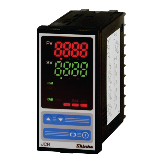
2. Name and functions of the sections (10) (10) (11) (11) (14) (14) (12) (15) (15) (12) (13) (13) (Fig. 2-1) (1) PV display Indicates the process variable (PV) with a red LED. (2) SV display Indicates the setting value (SV) or manipulated variable (MV) with a green LED. (3) SV1 indicator When SV 1 is selected, a green LED lights. - Page 9 (10) A1 indicator When A1 output is ON, a red LED lights. (11) A2/LA indicator When A2 output or La output is ON, a red LED lights. (12) Increase key ( Increases numeric value of the setting value. (13) Decrease key ( Decreases numeric value of the setting value.
-
Page 10: Mounting To Control Panel
(7) No water, oil or chemicals or where the vapors of these substances can come into direct contact with the unit 3.2 External dimension Gasket A Screw type mounting bracket • JCR-33A 11.5 98.5 (Fig. 3.2-1) • JCD-33A Gasket A Screw type mounting bracket 11.5... -
Page 11: Panel Cutout
3.3 Panel cutout • JCR-33A +0.5 n x 48-3 Lateral close mounting, n: Number of units mounted Caution:When lateral close mounting is used for the controller, IP66 specification is +0.5 not fulfilled. (Fig. 3.3-1) • JCD-33A +0.5 n×96-3 Lateral close mounting, n: Number of units mounted + 0.8... -
Page 12: Mounting
3.5 Mounting (both JCR-33A and JCD-33A) Warning As the case is made of resin, do not use excessive force while screwing in the mounting bracket, or the case could be damaged. The torque is approximately 0.12N•m. To fulfill the Dust-proof/Drip-proof IP66 specification, mount this unit vertically and check the rigidity of the panel where this unit is mounted. -
Page 13: Wiring Connection
4. Wiring connection Warning Turn the power supply to the instrument off before wiring or checking. Working or touching the terminal with the power switched on may result in Electric Shock causing severe injury or death. Moreover, the instrument must be grounded before the power supply to the instrument is turned on. -
Page 14: Wiring Connection Example
Caution • The terminal blocks of the JCR-33A and JCD-33A are designed to be wired from the left side. The lead wire must be inserted from the left side of the terminal, and fastened with the terminal screw. • Dotted lines show options. If the option is not designated, there are no terminals. - Page 15 CT. (3) When wiring, keep CT wire away from any AC sources and load wires to avoid the external interference. (Fig. 4.2-1) Heater [JCR-33A-R/E] 3-phase Electro- magnetic switch Alarm unit Heater...
-
Page 16: Setup
5. Setup For the thermocouple and RTD inputs, the sensor input characters and temperature unit are indicated on the PV display and the input range high limit value is indicated on the SV display for approximately 3 seconds after the power is turned on. (Table 5-1) For DC input, the sensor input characters are indicated on the PV display and the scaling high limit value is indicated on the SV display for approximately 3 seconds after the power is turned on. -
Page 17: Setup Flow Chart
5.1 Setup flow chart PV/SV display Control output OFF Output manipulated mode (Approx. 1s) function [ ] (*1) variable (Approx. 3s) (Approx. 3s) [ Main setting mode ] [Sub setting mode] [Auxiliary function setting mode1] SV 1 AT setting/Auto-reset Setting value lock setting [ selection [ SV 2... - Page 18 (Approx. 3s) [Auxiliary function setting mode2] Sensor selection Scaling high limit setting OUT2 low limit setting A1 action delayed timer setting [ Scaling low limit setting Overlap/Dead band setting A2 action delayed timer setting [ Decimal point place OUT2 ON/OFF action Direct/ Reverse action selection [ hysteresis setting [...
-
Page 19: Main Setting Mode
5.2 Main setting mode If the key is pressed, main setting mode is selected. The setting value (numeric value) can be increased or decreased by pressing the key. If the key is pressed, the setting value is registered and the controller will revert to the PV/SV display mode. -
Page 20: Out1 Proportional Band Setting
OUT1 proportional band setting [ ] • Sets OUT1 proportional band. ON/OFF action when set to 0 or 0.0. • Setting range: 0 to 1000 (0 to 2000 ) With a decimal point: 0.0 to 999.9 (0.0 to 999.9 ) DC input: 0.0 to 100.0% •... -
Page 21: A1 Setting
A1 setting [ • Sets the action point of A1 output. Setting the value to 0 or 0.0 disables the function. (Excluding process high alarm and process low alarm) • Not available when No alarm action is selected in the A1 action selection •... -
Page 22: Auxiliary Function Setting Mode
Since it has no relation to the memory life, this is suitable when used with Shinko programmable controller (with SVTC). •Default: Unlock SV high limit setting [ •... -
Page 23: Sv Low Limit Setting
Parity selection [ • Selects the parity of this unit. • Not available when the serial communication (option) is not applied or when Shinko protocol is selected in the Communication protocol selection • Selection item: (Shinko protocol) (Modbus RTU mode) (Modbus ASCII mode) •... -
Page 24: Auxiliary Function Setting Mode
5.5 Auxiliary function setting mode 2 In the PV/SV display mode, if the key is pressed while the keys are being pressed for approx. 3 seconds, Auxiliary function setting mode 2 can be selected. The setting value can be increased or decreased by pressing the key. -
Page 25: Scaling Low Limit Setting
Scaling low limit setting [ • Sets scaling low limit value. • Available only for the DC input • Setting range: Input range low limit value to scaling high limit value (The placement of the decimal point follows the selection.) •... -
Page 26: Out2 High Limit Setting
OUT2 high limit setting [ • Sets the high limit value for OUT2. • Not available when Heating/Cooling control (option) is not added or when OUT2 is ON/OFF action • Setting range: OUT2 low limit value to 100% (Relay contact output, Non-contact voltage output) OUT2 low limit value to 105% (DC current output) •... -
Page 27: A2 Action Energized/Deenergized Selection
A2 action Energized/Deenergized selection [ • Selects Energized or Deenergized for A2 action. • Not available when No alarm action is selected in the A2 action selection or when A2 (option) is not added • Selection item and default value are the same as those of A1 action Energized/ Deenergized selection. -
Page 28: Sv2 Indication Selection
SV2 indication selection [ • Selects whether SV2 is indicated or not. • Available only when serial communication (Option) is added • Selection item: (Indication), (No indication) • Default: Indication Output status selection when input burnout [ • Selects output status when input is burnt out. Available only for DC current output type with DC inputs •... -
Page 29: Control Output Off Function
A1 hysteresis A1 hysteresis + A1 set point SV setting + A1 set point SV setting High limit alarm (when Energized is set) High limit alarm (when Deenergized is set) (Fig. 5.5-1) (Fig. 5.5-2) 5.6 Control output OFF function Control output OFF function [ •... -
Page 30: Running
After the controller has been mounted to the control panel and wiring is completed, it can be started in the following manner. (1) Turn the power supply to the JCR-33A, JCD-33A ON. For thermocouple and RTD inputs, for approx. 3 seconds after the power is switched ON, sensor input character and temperature unit are indicated on the PV display, and the input range high limit value is indicated on the SV display. -
Page 31: Action Explanation
7. Action explanation 7.1 OUT1 action Heating (reverse) action Cooling (direct) action Proportional band Proportional band Control action SV setting SV setting Cycle action is performed according to deviation. Cycle action is performed according to deviation. 12V DC 12/0V DC 0V DC 0V DC 0/12V DC... -
Page 32: Out1 On/Off Actions
7.3 OUT1 ON/OFF action Heating (reverse) action Cooling (direct) action Hysteresis Hysteresis Control action SV setting SV setting 12V DC 0V DC 0V DC 12V DC 20mA DC 20mA DC 4mA DC 4mA DC Indication (OUT1) Green Unlit Unlit : Acts ON (lit) or OFF (unlit). -
Page 33: Out2 (Heating/Cooling Control) Action (Option)
7.4 OUT2 (Heating/Cooling control) action (option) Heating P-band (Cooling P-band) Control Heaing (Cooling action action action) SV setting Cycle action is performed according to deviation. Cycle action is performed according to deviation. 12V DC 12/0V DC 0V DC Cycle action is performed according to deviation. 0V DC 0/12V DC 12V DC... - Page 34 When setting Dead band Heating P-band Dead band (Cooling P-band) Heatng (Cooling Control action action action) SV setting Cycle action is performed according to deviation. Cycle action is performed according to deviation. 12V DC 12/0V DC 0V DC Cycle action is performed according to deviation. 0V DC 0/12V DC 12V DC...
- Page 35 When setting Overlap band with Relay contact output. Heating P-band Cooling P-band Overlap band Heating (Cooling Control action action action) SV setting Cycle action is performed according to deviation. Cycle action is performed according to deviation. Indication (OUT1) Green Unlit Indication (OUT2) Yellow Unlit...
- Page 36 7.5 A1 and A2 actions High limit alarm Low limit alarm A1 hysteresis A1 hysteresis Alarm action + Alarm Alarm Setting Alarm Setting + Alarm set point set point set point set point + side + side Alarm output side side High/Low limits alarm High/Low limit range alarm...
-
Page 37: Sv1/Sv2 External Selection Action
High/Low limits alarm with standby A1 hysteresis Alarm action SV setting set point set point Alarm output : A1 output terminals between 7 and 8 is ON. : A1 output terminals between 7 and 8 is ON or OFF. : A1 output terminals between 7 and 8 is OFF. : Standby functions. -
Page 38: Pid Auto-Tuning Of This Controller
(2) Integral time (I) Integral action is used to eliminate offset. When the integral time is shortened, the returning speed to the setting point is accelerated. However, the cycle of oscillation is also accelerated and the control becomes unstable. (3) Derivative time (D) Derivative action is used to restore the change in the processing temperature according to the rate of change. -
Page 39: Auto-Reset (Offset Correction)
(3) When the control temperature is 20 ( ) or higher than the setting value. Fluctuation is applied at the temperature 20 ( ) higher than the setting value. Temperature 20 ( ) higher than the setting value (1) Calculating PID Temperature constant (3) PID constant... -
Page 40: Specifications
: Membrane sheet key Display JCR-33A PV display: Red LED 4 digits, character size, 11.2 x 5.4 (H x W)mm SV display: Green LED 4 digits, character size, 11.2 x 5.4 (H x W)mm JCD-33A PV display: Red LED 4 digits, character size, 18 x 8 (H x W)mm SV display: Green LED 4 digits, character size, 12.6 x 6(H x W)mm... - Page 41 250V AC (inductive load cosø=0.4) Electrical life, 100,000 times Non-contact voltage : 12 V DC maximum 40mA (short circuit protected) Four units can be connected in parallel if Shinko SSR (SA-200 series) is used. DC current : 4 to 20mA DC...
- Page 42 • ON/OFF action OUT1 proportional band (P): Thermocouple, 0 to 1000 (0 to 2000 ) RTD, 0.0 to 999.9 (0.0 to 999.9 ) DC current and voltage, 0.0 to 100.0% (ON/OFF action when set to 0 ( ), 0.0 ( ) or 0.0%) Integral time (I) : 0 to 1000s (off when set to 0) Derivative time (D)
- Page 43 Between power terminal and ground terminal, 1.5kV AC for 1 minute Weight : JCR-33A (approx. 250g), JCD-33A, (approx. 370g) External dimension : JCR-33A, 48 x 96 x 100mm (W x H x D) JCD-33A, 96 x 96 x 100mm (W x H x D) Material : Case, Flame resistant resin...
- Page 44 • For DC current and voltage inputs, if the input value exceeds the Indication range high limit value , the PV display blinks “ ” and if the input value exceeds Indication range low limit value, the PV display blinks “ ”.
-
Page 45: Optional Specifications
1 piece [when option W(5A, 10A, 20A) is added] CTL-12-S36-10L1 1 piece [when option W(50A) is added] Terminal cover, JCR-33A 1 piece (when the option TC is added) JCD-33A 2 pieces (when the option TC is added) 9.2 Optional specifications Alarm 2 (option code: A2) When A2 action is set as Energized, the alarm action point is set by ±deviation to... - Page 46 SVTC). (It is necessary to set the Setting value lock function to Lock 3 for the JCR and JCD.) When the data from Shinko programmable controller exceeds SV high limit or SV low limit, the JCR or JCD ignores the value, and performs the control with SV high limit or SV low limit.
-
Page 47: Troubleshooting
Setting range : Loop break alarm action time, 0 to 200minutes Loop break alarm action span, 0 to 150 ( ), 0.0 to 150.0 ( ), For DC input, 0 to 1500 (The placement of the decimal point follows the selection) Output : Relay contact 1a, 3A 250V AC (Resistive load) Electrical life, 100,000 times... - Page 48 Problem Presumed cause and solution • The sensor for DC voltage (1 to 5V DC) or DC ] is blinking current (4 to 20mA DC) input may be burnt out. on the PV display. Replace each sensor. How to check sensor burnout [DC voltage (1 to 5V DC)] If the input to the input terminal of this controller is 1V DC and if scaling low limit value is indicated, the controller...
-
Page 49: Key Operation
Problem Presumed cause and solution PV display blinks The internal memory is defective. Please contact our main office or dealers. 10.2 Key operation Problem Presumed cause and solution Settings (main setting • Setting value lock (Lock 1 or Lock 2) is designated. value, P, I, D, Release the lock designation. -
Page 50: Character Table
SV high limit setting Input range high limit value SV low limit setting Input range low limit value Sensor correction setting Communication protocol selection Shinko protocol Instrument number setting Data transfer rate selection 9600bps Parity selection Even Stop bit selection... - Page 51 [Auxiliary function setting mode 2] Character Setting item Default value Data Sensor selection K: –200 to 1370 Scaling high limit setting 9999 Scaling low limit setting –1999 Decimal point place selection No decimal point PV filter time constant setting 0.0 seconds OUT1 high limit setting 100% OUT1 low limit setting...
- Page 52 • Instrument number ---------- No. xxxxxx In addition to the above, please let us know the details of the malfunction, if any, and the operating conditions. SHINKO TECHNOS CO.,LTD. OVERSEAS DIVISION 1-2-48, Ina, Minoo, Osaka, Japan Reg. Office P.O.Box 17, Minoo, Osaka, Japan Mail Address http://www.shinko-technos.co.jp...
Need help?
Do you have a question about the JCR-33A and is the answer not in the manual?
Questions and answers