Advertisement
Quick Links
ISO Registered Company
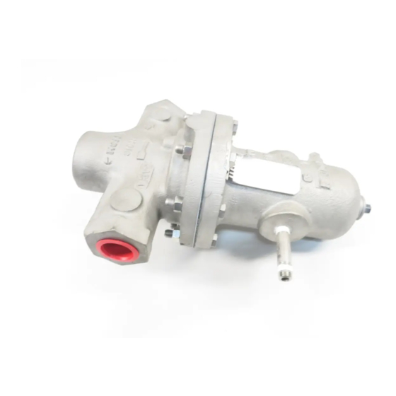
DIRECT-ACTING, POSITIVE BIAS DIFFERENTIAL
I. DESCRIPTION AND SCOPE
The Model DA2 is a differential pressure reducing regulator used to control differential pressure between down-
stream (outlet or P
2
(DN20), 1" (DN25), 1-1/4" (DN32), 1-1/2" (DN40), 2" (DN50), 2-1/2" (DN65), 3" (DN80) and 4" (DN100). With
proper trim uti li za tion, the unit is suitable for liquid, gaseous, or steam service. Refer to Technical Bulletin DA2-
TB for design conditions and selection recommendations.
II. REFERENCES
Refer to Technical Bulletin DA2-TB and DAG-TB for
tech ni cal specifications.
III. INSTALLATION
1. Regulator may be rotated around pipe axis 360
degrees. For ease of maintenance, the recom-
mended position is with the spring chamber (4)
upwards. In liquid service it is recommended that
the spring cham ber (4) be oriented downwards,
and that a cus tom er supplied and installed vent
valve be pro vid ed at the external sensing con-
nec tion to bleed-off trapped gas/air under the
di a phragm.
2. Provide space below, above, and around reg u la-
tor for removal of parts during maintenance.
3. Install block valves and pressure gauges to pro-
vide means for adjustment, operation, bypass,
or removal of the regulator. An isolation valve
on the loading line is not rec om mend ed.
4. An outlet pressure gauge should be located ap-
prox i mate ly ten pipe diameters downstream, and
within sight. A loading pressure (or differential
pressure) gauge is rec om mend ed.
5. All installations should include a downstream
re lief device if the inlet pressure could exceed
the pressure rating of any downstream equip-
ment or the maximum outlet pressure rating of
the unit.
INSTALLATION, OPERATION & MAINTENANCE MANUAL (IOM)
MODEL DA2
PRESSURE REDUCING REGULATOR
) pressure and a loading (P
SECTION I
) pressure to the spring chamber. Sizes 1/2" (DN15), 3/4"
Load
SECTION II
CCW – Counter Clockwise
CW
ITA
SECTION III
6. Clean the piping of all foreign material including
chips, welding scale, oil, grease and dirt before
in stall ing the regulator. Strainers are rec om-
mend ed.
7. In placing thread sealant on pipe ends prior to
en gage ment, ensure that excess material is
re moved and not allowed to enter the regulator
upon startup.
8. Flow Direction: Install so the flow direction
match es the arrow cast on the body.
9. If the loading pressure is not lowered sufficiently
prior to shutting off the process fluid supply,
then the diaphragm will be damaged with the
standard construction. The startup, shutdown,
and emergency operating procedures should be
reviewed to ensure that the loading pressure is
less than 50% of the Diaphragm Proof Rating
(See Table 1) before shutting off the process fluid
supply pressure. If the regulator is specified with
a fully supported diaphragm, then the diaphragm
will withstand a loading pressure equal to the
Diaphragm Proof Rating for the fully supported
diaphragm.
ABBREVIATIONS
– Clockwise
– Inner Trim Assembly
IOM-DA2
03-16
Advertisement

Related Manuals for cashco DA2


Summary of Contents for cashco DA2
- Page 1 (DN20), 1" (DN25), 1-1/4" (DN32), 1-1/2" (DN40), 2" (DN50), 2-1/2" (DN65), 3" (DN80) and 4" (DN100). With proper trim uti li za tion, the unit is suitable for liquid, gaseous, or steam service. Refer to Technical Bulletin DA2- TB for design conditions and selection recommendations.
- Page 2 Pressure Rating shown on the nameplate. For exam- control line. The line is connected from the port ple, a 1" DA2 with Cast Iron Body and Spring Chamber, (1/4" NPT) on the side of the body di a phragm Neoprene Diaphragm (BC) has an Outlet Pressure Rat- flange (see port 5 in Fig.
-
Page 3: Principle Of Operation
2. For a DA2 (single diaphragm) design, a com plete diaphragm failure will cause the outlet process the valve seat. The outlet pressure acting on the topside of the diaphragm tends to lift the valve fluid to mix with the loading fluid. -
Page 4: Maintenance
20 ..... All ...........Valve Plug parts. Only use original equipment parts sup- 21 ..... All ..........Seat Ring plied by Cashco for re build ing or re pair ing 27 ..... All ......Dynamic Side Seal regulators. 27.1 ... CP,CW ......... TFE Cap Seal 27.2 ...CP, CW ...... - Page 5 Dynamic Seal Dynamic Seal + Wiper Piston Rings (2) w/Metal Energizer 27.5 27.5 27.3 SECTION "A" 17.3 17.1 Type UC — U-Cup Type PW — PRA Dy nam ic Dynamic Seal Seal + Wiper Figure 1: Dynamic Side Seals IOM-DA2...
- Page 6 (19). termine if op er at ing conditions are exceeding b. For a regulator with a metal diaphragm(s) pressure, pressure drop or temperature limits. (see figure 3); hold the lower part of the IOM-DA2...
- Page 7 Inspect and clean parts, as necessary, tion-55, -56, or -57, maintenance must include from the spare parts kit. (See Article a level of clean li ness equal to Cashco clean- VII.A.4. comments concerning cleaning ing standards of #S-1134, #S-1542, #S-1589 for ox y gen service.)
- Page 8 Using thumbs, work the o-ring en- (19). ergizer/seal (27.4) up and into the groove of the piston-guide bear ing (13). NOTE: A very slight amount of fluid and elas tomer compatible o-ring lubricant is rec om mend ed as an installation aid. IOM-DA2...
- Page 9 (27.3) is oriented with the center-open- down wards as shown in Figure 1. The CAP SEAL (27.1) INTO THE CAGE u-cup seal (27.3) depends upon the (19). P1-Inlet Pres sure to activate the seal for proper seal ing action. IOM-DA2...
- Page 10 (20) as far as possible manually. 1/2" - 1" (15-25) 30-50 (41-68) h. Place a wrench on diaphragm lock nut (7) and a torque wrench on the upper end 1 1/4" - 2" (32-50) 45-70 (61-95) e. This completes ITA reassembly. IOM-DA2...
- Page 11 1/4" NPT (plugged) external pres- c. Position upper diaphragm pressure plate sure sens ing connection on the valve (8) onto center top of diaphragm(s)) (9) diaphragm flange. with counterbore upwards. c. Leave pressure on through tightening of bolt ing (11,12). IOM-DA2...
- Page 12 Tube outlet to a beaker of water to ob- serve number of escaping gas bubbles. 2. For a Model DA2 the only “special” part to be supplied is the support plate (35) fitted into 3. Excessive leakage will require disassembly, a counter bore cut into the body (23).
-
Page 13: Section Viii
3. Downstream pressure will not reach desired setting. Possible Causes Remedies A. Supply pressure is down (conformation pressure gauge). A. Increase supply pressure. B. Undersized regulator. B. Check actual flow conditions; resize regulator for minimum and maximum flow; if necessary, replace with larger regulator. IOM-DA2... - Page 14 B. Check actual flow conditions; resize regulator for minimum seat. and maximum flow; if necessary, replace with smaller regulator. * Excess seat leakage may be diagnosed when a failure of the dynamic side seal has occurred. Inspect both potential internal leak paths. IOM-DA2...
- Page 15 Cashco, Inc. does not assume responsibility for the selection, use or maintenance of any product. Responsibility for proper selection, use and maintenance of any Cashco, Inc. product remains solely with the purchaser.
- Page 16 Wiper Seal ** Reference Figure 1 for details of Item #27 - Dynamic Side Seal. *** Not utilized on metal diaphragm construction. ‡‡ Recommended Repair Parts Cashco GmbH Cashco do Brasil, Ltda. Cashco, Inc. Handwerkerstrasse 15 Al.Venus, 340 P.O. Box 6...
Need help?
Do you have a question about the DA2 and is the answer not in the manual?
Questions and answers